Transcription
PCD3191.2 Saia PCD3 seriesDesign of the Saia PCD3 series1Page 20Description of the basic structure and general featuresof the modular Saia PCD3 seriesSaia PCD3.Mxxxx controllersAutomationstations1.2.1 Saia PCD3 controllersPage 22Up to 5 integrated communication interfaces that can be expanded byup to 13 communication interfaces using plug-in modules.Integrated Automation Server in all CPUs.Saia PCD3.Txxx remote I/O stations RIOsPage 35Remote peripheral nodesSmart Ethernet RIOProfibus RIOSaia PCD3.Cxxx module holder for I/O expansionPage 21 PCD3.C100 PCD3.C110 PCD3.C200Dedicatedroom controllersModule holder for I/O modules4 I/O slots2 I/O slots4 I/O slots with 24 VDC power supplyExpandable up to 1023 I/OsSaia PCD3 input/output modules in cassette designPage 263 PCD3.T66x PCD3.T7602 PCD3.Mxx60 High Power CPU PCD3.M5xxx Standard CPU PCD3.M3xxx Minimum Basic CPUOperationand monitoringBase units with 4 slots for I/O modulesModules with various functions with plug-in terminalsPage 31Plug-in modules to expand the communication interfaces(up to 4 modules or 8 interfaces) PCD3.F1xx PCD3.F2xx1 serial interface RS-232, RS-422/4852 serial interfaces RS-232, RS-422/RS-485 BACnet MSTP, DALI,M-Bus, Belimo MP-BusSaia PCD3 memory modulesPage 32Plug-in memory modules for data and program backup PCD3.R5xxFlash memory module for slots 0 3 PCD3.R6xxBasic module for SD flash card for slots 0 3 PCD7.R-SDSD Flash cards for PCD3.R6xx PCD7.R5xxFlash memory module for slots M1 and M2 PCD7.R610Basic module for micro SD flash card PCD7.R-MSD Micro SD flash cards for PCD7.R610Consumables and accessories for Saia PCD3 controllersPage 335Batteries, terminals, system cables, labelling accessories 4Saia PCD3 interface modulesConsumerdata acquisitionDigital output modulesCombined digital input/output modulesDigital input modulesAnalogue input/output modulesSwitch cabinetcomponents PCD3.Axxx PCD3.Bxxx PCD3.Exxx PCD3.WxxxAutomation stations – Saia PCD3 saia-pcd.com
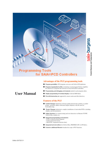
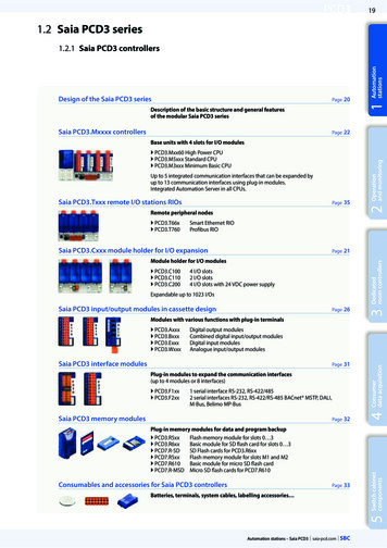
20PCD3Design of Saia PCD3 controllersThe CPU has been incorporated into the back panel of the device, unlike comparablesystems. Its capacity can be increased individually with plug-in communication modulesand/or intelligent I/O modules. These have a direct, very fast bus connection to the CPU.PCD3.Mxxxxx base unitBase unit with CPU and 4 slots for I/O modules, communication or other specific modules (e.g. PCD3.Hxxx counter modules)Device designMemory modulesFast serial bus (SPI) forrunning up to 4 intelligent modules4 slots for I/O modules, communication modules orother intelligent modulesBatterymoduleI/O bus forstandardmodulesGround connection for I/OmodulesRUN/STOPswitchRS-232 PGU(Port 0)Saia PCD3.M 5540RS-422/485 (Port3 or 10)Expansion connectionfor I/O module holderEthernetconnectionRUN/STOP LEDindicatorEarth connectionUSB connectionThe CPU is incorporated into the backpanel. An additional 4 I/O modules cantherefore be inserted into the same area.24 VDC power supply, RS-485interface (Port 2),Watchdogrelay, interrupt inputsWith the left expansion, the Standard (PCD3.M5/M6xxx) and High Power (PCD3.Mxx60) CPU types have slots for a battery holdermodule with LED indicators, a run/stop switch, two slots for flash memory modules and two additional communication interfaces.The LED indicators on the battery module display the status of the CPU and battery and any errors in the application. The batteryalso protects the data in the event of an interruption to the power supply. It can be replaced during operation while under power.The configuration, programs and data can be transferred from one controller to another using the plug-in flash memory modules.No programming tool is required for PCD3.M3xx0 without left expansion28.518063.8130125.8180 100.5 139 mm (W H D)c Standard and High Power CPU with slots for batteryand memory modules, run/stop switch and additionalinterfacessaia-pcd.com Automation stations – Saia PCD3139130 100.5 139 mm (W H D)c Minimum Basic CPU without battery module.PCD3.Rxxx memory modules are plugged intoan I/O slot.
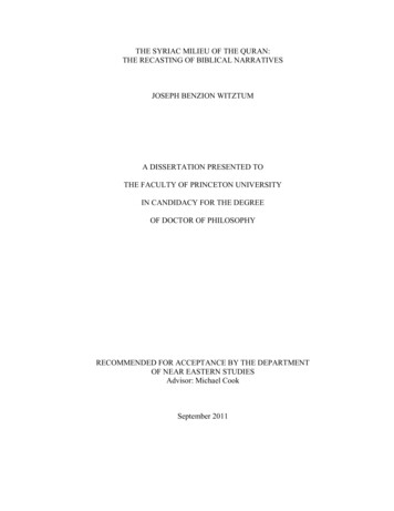
PCD321Saia PCD3.Cxxx module holderI/O bus forstandardmodulesTerminal for CPUor I/O moduleholderAvailable typesLED indicator forinternal 5 V supply voltage PCD3.C100 Expansion module holder with 4 I/O slots PCD3.C110 Expansion module holder with 2 I/O slots PCD3.C200 Expansion module holder with 4 I/O slots andterminal connectors for 24 VDC power supply for all connectedI/O modules, plus any downstream PCD3.C1xx module holdersSaia PCD3.C 200Groundconnection24 VDC powersupply terminalExpansion connectionfor I/O module holderPCD3.C100/200 with 4 I/O slots433PCD3.C110with 2 I/O slotsOperationand monitoringGround connection for I/OmodulesAll standard I/O modules can be used inthe expansion module holders. Communication modules or other intelligentmodules can only be used in the slots ofthe Basic CPU.24 slots for I/O modulesDedicatedroom controllersDevice design1AutomationstationsI/O expansion module holders are available in either a 2- or 4-slot version.This enables users to expand the PCD3 controllers to a max. 64 I/O modulesor a max. 1023 I/O modules.1661302Easy assembly of the CPUsand module holders on DIN rail(1 35 mm)E110E110E500B100B100B100A2004E110PCD3.C100I/O module holder4 slotsPCD3.K1xxExtension cable formultiple-row mountingSaia PCD3.M 5540PCD3.C200I/O module holder4 slotsB100B100PCD3.C110I/O module holder2 slotsE110A200Saia PCD3.C 200H110W745Saia PCD3.C C110PCD3 in multiple-row mounting in the switch cabinetExtension plug and cables PCD3.K010 Extension plug PCD3.K106 Extension cable 0.7 m PCD3.K116 Extension cable 1.2 mExtension plug PCD3.K0105Extension plug PCD3.K010Saia PCD3.C 100Switch cabinetcomponentsPCD3.M5540CPU incl. 4 I/O slotsConsumerdata acquisitionSystem expansion up to 1023 I/OSingle- and multiple-row mounting of the module holdersAutomation stations – Saia PCD3 saia-pcd.com
PCD3Saia PCD3.Mxx60 controllersHigh-performance CPU for any requirementThe fast processor and increased system resources provide the High Power CPU with sufficient power reserves toprocess the most demanding control and communication tasks.System properties Up to 1023 inputs/outputsCan be expanded remotely with RIO PCD3.T66x or PCD3.T76x Up to 13 communication interfaces Onboard USB and Ethernet interface 2 Ethernet interfaces (PCD3.M6860 only) Fast program processing (0.1μs for bit operations) Large onboard memory for programs (2 MB) and data(128 MB file system) Memory with SD flash cards can be expanded up to 4 GB Automation Server for integration in Web/IT systemsSNMPAutomation Serverintegrated in the baseunitTypes PCD3.M5560 CPU basic module with Ethernet TCP/IP,2 MB of program memory PCD3.M6560 CPU basic module with Ethernet TCP/IPand Profibus-DP Master 12 Mbits, 2 MB of program memory PCD3.M6860 CPU basic module with 2 Ethernet TCP/IP,2 MB of program evelManagementlevelBACnet Saia PCD3.C 5560ModbusLON IPProfibusCANKNX-EIBMP ield levelThe Saia PCD3 Power CPU has sufficient system resources to operate up to 13 communication interfaces inthe same device. Even the most demanding tasks, suchas simultaneous communication via BACnet and Lon IP,are handled reliably.saia-pcd.com Automation stations – Saia PCD3Heating – ventilation – air conditioning – plumbing – electricalField levelThe generous memory resources (4 GB) of the new PCD3 PowerCPU enable users to record/monitor, archive and control thedata and statuses of all plants in the Saia PCD , even with nocomputer equipment and control system software. Applicationsfor the various plants (HVAC) can be created easily using thegraphic PG5 engineering tool and application-specific softwarelibraries.
PCD323Saia PCD3.Mxx60 controllers2 MB0.1/0.3 µsbit/wordTechnical DataFile system14.2 GBI/OProgramCPU speedPCD3.M5560PCD3.M6560PCD3.M6860PowerPowerDP MasterPower2 Ethernet1023or I/O module slots64I/O expansion connection for PCD3.Cxxx module holderYesProcessing time [µs]bit operationword operation2Number of inputs/outputsOperationand monitoring1023AutomationstationsHigh-performance CPU0.1 0.8 µs0.3 µsReal-time clock (RTC)YesProgram memory, DB/text (flash)Dedicatedroom controllersOnboard memory2 MBUser memory, DB/text (RAM)1 MBFlash memory (S-RIO, configuration and backup)128 MBUser flash file system (INTFLASH)128 MB1 3 years with lithium battery3Data backupOnboard interfacesYesEthernet 10/100 Mbits, full-duplex, auto-sensing/auto-crossingRS-232 on D-Sub connector (PGU/Port 0)Yes2 up to 115 kbitsNoRS-485 on terminal block (Port 2)or RS-485 Profibus-DP Slave, Profi S-Net on terminal block (Port 2)up to 115 kbitsNoup to 115 kbitsup to 187.5 kbitsup to 115 kbitsup to 187.5 kbitsRS-485 on D-Sub connector (Port 3) *or Profibus-DP Slave, Profi S-Net on D-Sub connector (Port 10) *or Profibus-DP Master up to 12 Mbits on D-Sub connector (Port 10) *Up to 115 kbitsUp to 1.5 MbitsNoNoNoYesNoNoNo4* can be used as an alternative, electrically isolatedConsumerdata acquisitionUSB 1.1OptionsThe data memory can be expanded to 4 GB with flash memory modules (with file system).Optional data interfacesI/O slot 0PCD3.F1xx modules for RS-232, RS-422, RS-485 and Belimo MP-BusGeneral specifications24 VDC, –20/ 25% max. incl. 5% ripple or 19 VAC 15% two-way rectified (18 VDC)Power consumptiontypically 15 W for 64 I/OsCapacity 5 V/ V (24 V) internalmax. 600 mA/100 mA5Supply voltage(in accordance with EN/IEC 61131-2)Switch cabinetcomponentsI/O slot 0 3 up to 4 modules or 8 interfaces: PCD3.F2xx modules for RS-232, RS-422, RS-485, BACnet MS/TP, Belimo MP-Bus, DALI and M-BusAutomation stations – Saia PCD3 saia-pcd.com
24PCD3Saia PCD3.M5x40 controllersThe standard CPU for many applications1023I/O4 GBFile system1 MBProgram0.3/0.9 µsbit/wordCPU speedTypesSNMPAutomation Serverintegrated in the baseunit PCD3.M5340 CPU basic module with Ethernet TCP/IP,1 MB program memory PCD3.M5440 CPU basic module without Ethernet TCP/IP,1 MB program memory PCD3.M5540 CPU basic module with Ethernet TCP/IPand Profibus-DP Slave 1.5 Mbits, 1 MB program memoryPCD3.M5340StandardTechnical DataNumber of inputs/outputsor I/O module slotsbit operationPCD3.M5540Standard102364I/O expansion connection for PCD3.Cxxx module holderProcessing time [µs]Real-time clock (RTC)PCD3.M5440StandardYes0.3 1.5 µsword operation0.9 µsYesOnboard memoryMain memory (RAM) for program and DB/TEXT1 MBFlash memory (S-RIO, configuration and backup)2 MBUser flash file system (INTFLASH)NoData backup1 3 years with lithium batteryOnboard interfacesUSB 1.1YesEthernet 10/100 Mbits, full-duplex, auto-sensing/auto-crossingYesRS-232 on D-Sub connector (PGU/Port 0)NoYesup to 115 kbitsRS-485 on terminal block (Port 2) or RS-485 Profibus-DP Slave,Profi S-Net on terminal block (Port 2)RS-422/485 (electrically connected) on D-Sub connector (Port 3) *RS-485 (electrically isolated) on D-Sub connector (Port 3) *Profibus-DP Slave, Profi S-Net on D-Sub connector (Port 10) *up to 115 kbitsup to 187.5 kbitsup to 115 kbitsNoNoup to 115 kbits NoNoup to 115 kbitsup to 1.5 Mbitsup to 115 kbits NoNoup to 115 kbitsup to 1.5 Mbits* can be used as an alternativeOptionsThe data memory can be expanded to 4 GB with flash memory modules (with file system).Optional data interfacesI/O slot 0PCD3.F1xx modules for RS-232, RS-422, RS-485 and Belimo MP-BusI/O slot 0 3up to 4 modules or 8 interfaces:PCD3.F2xx modules for RS-232, RS-422, RS-485, BACnet MS/TP, Belimo MP-Bus, DALI and M-BusGeneral specificationsSupply voltage (in accordance with EN/IEC 131-2)24 VDC, –20/ 25% max. incl. 5% ripple or 19 VAC 15% two-way rectified (18 VDC)Power consumptiontypically 15 W for 64 I/OsCapacity 5 V/ V (24 V) internalmax. 600 mA/100 mAsaia-pcd.com Automation stations – Saia PCD3
PCD325Saia PCD3.M3xx0 controllersI/O4 GBFile system512 kByteProgram0.3/0.9 µsbit/wordCPU speedTypesAutomation Serverintegrated in the baseunitPCD3.M3230PCD3.M3330BasicBasicBasicNumber of inputs/outputs6410231023or I/O module slots46464YesYesI/O expansion connection for PCD3.Cxxx module holderProcessing times [µs]bit operationNo0.3 1.5 µs0.9 µsword operationReal-time clock (RTC)YesOnboard memoryMain memory (RAM) for program and DB/text128 kByteFlash memory (S-RIO, configuration and backup)512 kByte512 kByte3Technical DataPCD3.M3120Dedicatedroom controllers2SNMP PCD3.M3120 CPU basic module with Ethernet TCP/IP, 64 I/Os,128 kByte of program memory PCD3.M3230 CPU basic module without Ethernet TCP/IP,1023 I/Os, 512 kByte of program memory PCD3.M3330 CPU basic module with Ethernet TCP/IP,1023 I/Os, 512 kByte of program memoryOperationand monitoring11023AutomationstationsThe base CPU for simple applications2 MBUser flash file system (INTFLASH)NoData backup4 hours with SuperCapUSB 1.1YesEthernet 10/100 Mbits, full-duplex, auto-sensing/auto-crossingNoYesup to 115 kbitsup to 187.5 kbits4RS-485 on terminal block (Port 2) orRS-485 Profibus-DP Slave, Profi-S-Net on terminal block (Port 2)YesConsumerdata acquisitionOnboard interfacesOptionsThe data memory can be expanded to 4 GB with flash memory modules (with file system).I/O slot 0PCD3.F1xx modules for RS-232, RS-422, RS-485 and Belimo MP-BusI/O slot 0 3up to 4 modules or 8 interfaces:PCD3.F2xx modules for RS-232, RS-422, RS-485, BACnet MS/TP, Belimo MP-Bus, DALI and M-BusGeneral specificationsPower consumptiontypically 15 W for 64 I/OsCapacity 5 V/ V (24 V) internalmax. 600 mA/100 mA5Supply voltage (in accordance with EN/IEC 61131-2) 24 VDC, –20/ 25% max. incl. 5% ripple or 19 VAC 15% two-way rectified (18 VDC)Switch cabinetcomponentsOptional data interfacesAutomation stations – Saia PCD3 saia-pcd.com
26PCD3Saia PCD3 input and output modules in cassette designThe functions of the Saia PCD3 can be expanded as required using a wide range of plug-in I/O modules and can be adapted to specificrequirements. This not only ensures that a project can be implemented quickly, but also provides the option of expanding or modifyingthe system at any time.System properties Numerous variants available Slot direct in the Saia PCD3 basic CPUor in the module holder Full integration in the Saia PCD3 housing Stable cartridge constructionPlug-in terminals Connection to the I/O level via plug-in springterminal blocks or ribbon cables and adaptersNameplate withconnectiondescriptionLED for statusindication I/O terminal blocks are supplied as standard No tools required for replacing modulesInsertion of I/O modulesOver 50 modules available with different functionalitiesPCD3 with 4 modulepositionsClipsGuidewayTypes PCD3.Axxx PCD3.Bxxx PCD3.Exxx PCD3.Fxxx PCD3.Hxxx PCD3.Rxxx PCD3.WxxxDigital output modulesCombined digital input/output modulesDigital input modulesCommunication modulesFast counter modulesMemory modulesAnalogue input/output modulesAdditionalsafeguardwith screwLabel holderc Simple exchange of I/O modulesConnecting plugs/terminalsType A10-pin2.5 mm2E111Type C24-pin 1.0mm2E165Type E14-pin 1.5mm2Type F12-pin 1.5mm2W325A810Type JType G H4- 6-pin 2.5 8-pin 1.52mm2 1.5 mmA866W800Type K10-pin1.0 mm2B160 Spare terminals, ribbon connectors with system cables and separate terminals are ordered as accessories.saia-pcd.com Automation stations – Saia PCD3Type DConnecting plug for ribbon cable(not supplied with the module)EA41601
PCD327Input delayElectricalisolationInternal current draw I/O connectortype 3)5 V-Bus 1) V-Bus 2)PCD3.E110PCD3.E111PCD3.E112PCD3.E1168I8I8I8I15 30 VDC15 30 VDC7.5 15 VDC3.5 7 VDC------8 ms0.2 ms9 ms0.2 ms---24 mA24 mA24 mA24 mA---AAAAPCD3.E160PCD3.E16116 I16 I15 30 VDC15 30 VDC------8 ms0.2 ms---10 mA10 mA---DDPCD3.E165PCD3.E16616 I16 I15 30 VDC15 30 VDC------8 ms0.2 ms---10 mA10 mA---CCPCD3.E5006I80 250 VAC------20 msƔ1 mA---APCD3.E610PCD3.E6138I8I15 30 VDC30 60 VDC------10 ms9 msƔƔ24 mA24 mA---AAInput delayElectricalisolationDigital output modulesNumber of I/OsInput voltagePCD3.A200PCD3.A2104 A, relay (make) 4 A, relay(break)---2 A/50 VDC2 A/50 VDC2 A/250 VAC2 A/250 VAC---ƔƔ15 mA15 mA---AAPCD3.A2206 O, relay (make)---2 A/50 VDC2 A/250 VAC---Ɣ20 mA---APCD3.A2518 O, relay(6 changeover 2 make)---2 A/50 VDC2 A/48 VAC---Ɣ25 mA---CPCD3.A3006 O, transistor---2 A/10 32 VDC---------20 mA---APCD3.A4008 O, transistor---0.5 A/5 32 VDC---------25 mA---APCD3.A4108 O, transistor---0.5 A/5 32 VDC------Ɣ24 mA---APCD3.A460PCD3.A46516 O, transistor16 O, transistor---0.5 A/10 32 VDC0.5 A/10 32 VDC---------10 mA10 mA---DC4 O, relay (2 changeover 2 make)---2 A/50 VDC2 A/50 VDC5 A/250 VAC6 A/250 VAC---ƔƔ40 mA---FInput delayElectricalisolation8 msƔ18 mA---GHPCD3.A810Manual operationOutput switching capacityDC ACInternal current draw I/O connectortype 3)5 V-Bus 1) V-Bus 2)Digital input/output modulesPCD3.A860Light and shadePCD3.B100Number of I/OsInput voltage2 O, relay (make) 2 I15 30 VDC2 I 2 O 4 selectable I or O I: 15 32 VDCPCD3.B16016 I/O (configurable)I: 24 VDCOutput switching capacityDC ACInternal current draw I/O connectortype 3)5 V-Bus 1) V-Bus 2)---12 A/250 VAC0.5 A/5 32 VDC---8 ms---25 mA---A---8 ms or0.2 ms---120 mA---2 K0.25 A/18 30 VDCConsumerdata acquisitionTypeFast counter modules (only for I/O slots with fast SPI bus)TypeNumberof countersInputs per counterOutputs per Counting rangecounterSelectable digitalfilterCurrent draw 5 VBus 1) V-Bus 2)I/O connectortype 3)PCD3.H11222 I 1 configurable I1 CCO0 16 777 215 (24 Bit)10 kHz 150 kHz50 mA4 mAKPCD3.H11442 I 1 configurable I1 CCO0 16 777 215 (24 Bit)10 kHz 150 kHz50 mA4 mA2 K4Type1Output switching capacityDC ACOperationand monitoringInput voltage2Number of I/OsDedicatedroom controllersDigital input modulesType3The digital I/O modules can be easily plugged into the Saia PCD3 Basis CPU or an appropriate module holder. In addition to inputs forvarious voltage levels, digital outputs are provided with both transistor construction and as mechanical relays. This means that electricalisolation from the switching electrical circuit can be achieved easily and reliably.AutomationstationsSaia PCD3 digital input and output modulesPCD3.Mxxx0PCD3.TxxxPCD3.C2001)Internal 5V600 mA600 mA1500 mA2)Internal V (24 V)100 mA100 mA200 mAThe electrical requirement of the internal 5V and V bus for the I/O modules iscalculated in the PG5 2.0 Device Configurator.3)Plug-in terminal blocks are included with I/O modules. Spare terminals, ribbon connectors with system cables and separateterminals are ordered as accessories (see pages 34 and 160).Automation stations – Saia PCD3 saia-pcd.com5CapacitySwitch cabinetcomponentsOverview of the internal bus capacity of the module holders
28PCD3Saia PCD3 analogue input and output modulesThe numerous analogue modules allow complex control tasks or measurements to be performed. The resolution is between 8 and16 bits, depending on the speed of the AD converter. The digitised values can be further processed direct in the project in theSaia PCD3. The large number of different modules means that suitable modules are available for almost any requirement.Analogue input modulesTypeTotalChannelsSignal .W220PCD3.W220Z03PCD3.W220Z128I8I8I8I4I4I 0 10 V0 20 mA 4)Pt1000: –50 C 400 C/Ni1000: –50 C 200 CNTC 10 temperature sensor4 I: 0 10 V4 I: Pt1000: –50 C 400 C/Ni1000: –50 C 200 C10 Bit10 Bit10 Bit10 Bit10 BitPCD3.W300PCD3.W310PCD3.W3408I8I8I12 Bit12 Bit12 BitPCD3.W350PCD3.W360PCD3.W3808I8I8I0 10 V0 20 mA 4)0 10 V/0 20 mA 4)Pt1000: –50 C 400 C/Ni1000: –50 C 200 CPt100: –50 C 600 C/Ni100: –50 C 250 CPt1000: –50 C 150 C–10 V 10 V, –20 mA 20 mA, Pt/Ni1000, Ni1000 L&S,NTC10k/NTC20k (configuration using software)PCD3.W305PCD3.W315PCD3.W3257I7I7I0 10 V0 20 mA 4)–10 V 10 V12 Bit12 Bit12 BitPCD3.W7202IWeighing module with 2 systems for up to 6 weighing cells 18 Bit4ITemperature module for TC type J, K and 4-wire Pt/Ni100/1000PCD3.W745ElectricalisolationI/O connector type 3)8 mA8 mA8 mA8 mA8 mA5 mA5 mA16 mA16 mA11 mAAAAAA8 mA8 mA8 mA5 mA5 mA20 mAAAA8 mA8 mA25 mA30 mA20 mA25 mAAA2 KƔƔƔ60 mA60 mA60 mA0 mA0 mA0 mAIII---60 mA100 mA------12 Bit12 Bit13 BitInternal current draw5 V-Bus 1) V-Bus 2)16 BitƔ ResolutionElectricalisolationI6)200 mA0 mAAnalogue output modulesTypeNumber ofchannelsSignal ranges/descriptionPCD3.W400PCD3.W4104O4O0 10 V0 10 V/0 20 mA/4 20 mA jumper-selectable8 Bit8 BitPCD3.W600PCD3.W6104O4O0 10 V0 10 V/–10 V 10 V/0 20 mA/4 20 mA jumperselectable12 Bit12 BitPCD3.W605PCD3.W615PCD3.W6256O4O6O0 10 V0 20 mA/4 20 mA parameters can be set–10 V 10 VPCD3.W800Internal current draw5 V-Bus 1) V-Bus 2)I/O connector type 3)1 mA1 mA30 mA30 mAAA---4 mA110 mA20 mA0 mAAA10 Bit10 Bit10 BitƔƔƔ110 mA55 mA110 mA0 mA0 mA0 mAIII10 Bit---45 mA35 mA 5)JResolutionElectricalisolationI: 14 BitƔ4 O, 3 of which are 0 10 V, short circuit-proofedmanually operated---Analogue input/output modulesTypeNumber ofchannelsPCD3.W5254I 2OSignal ranges/descriptionI:0 10 V, 0(4) 20 mA, Pt1000, Pt500 or Ni1000(selectable via DIP switch)Internal current draw5 V-Bus 1) V-Bus 2)40 mA0 mAI/O connector type 3)IO: 12 BitO: 0 10 V or 0(4) 20 mA (selectable via software)Manual control modulesPCD3.A860PCD3.A810Relay outputs, 2 change- Light and shade 2 relayoutputs and 2 inputsover and 2 makeOverview of the internal bus capacity of the module holdersPCD3.W8004 analogue outputs(3 of these ernal 5V600 mA600 mA1500 mA2)Internal V (24 V)100 mA100 mA200 mAThe electrical requirement of the internal 5V and V bus for the I/O modules iscalculated in the PG5 Device Configurator.3)4)saia-pcd.com Automation stations – Saia PCD3Plug-in I/O terminal blocks are included with I/O modules.Spare terminals, ribbon connectors with system cables and separate terminalsare ordered as accessories (see pages 34 and 160).4 20 mA via user program5)At 100% output value and 3 kΩ load6)With soldered spring terminal block
PCD329Information for project planning with PCD3 module holdersAutomationstationsThe internal load current taken by the I/O modules from the 5V and V (24V) supply must not exceed the maximum supply currentspecified for the CPUs, RIOs or PCD3.C200 module holders.Example calculation for the current consumption of the internal 5V and V (24V) bus of the I/O modulesPCD3.C100I/O module holder4 1PCD3.C100I/O module holder4 slotsE160WE61160PCD3.C100I/O module holder4 slotsSaia PCD3.M 5540Saia PCD3.C 100Saia PCD3.C 100Extension plugPCD3.K010Extension cablePCD3.K106PCD3.C200I/O module holder4 slotsA200A810A810A860A460A460Saia PCD3.C 200A460W380Saia PCD3.C 1002Extension plug PCD3.K010Operationand monitoringPCD3.M5540CPU incl. 4 I/O slots15 mA20 mA35 mA20 mA20 mA0 mA40 mA075 mAInternal V (24V)CapacityPCD3.M5540Internal 5V600 mAInternal V (24V) 100 mAPCD3.C2001500 mA200 mA25 mA25 mA25 mA3110 mA90 mA8 mA208 mA8 mA8 mA110 mA10 mA136 mA10 mA10 mA10 mA10 mA40 mA384 mAInternal 5V15 mA40 mA40 mA18 mA113 mA10 mA10 mA10 mA25 mA55 mA168 mADedicatedroom controllersModuleA200A810A810A860Total C200A460A460A460W380Total C100Total C200Internal 5V Internal V (24V)The calculation example shows that internal capacity is maintained in the CPU basic module PCD3.M5540 and the holder module PCD3.C200. The CPU basic module has a sufficientreserve to receive an additional communication module in the empty slot 0. The holdermodule PCD3.C200 also has sufficient reserves to connect an additional PCD3.C100 orPCD3.C110 holder module. The power consumption of the internal 5V and V (24 V) busfor the I/O modules is automatically calculated in the PG5 2.0 Device Configurator.The following aspects should be considered when planning PCD3 applications: In keeping with lean automation, it is recommended to leavethe first slot in the CPU basic module free for any subsequentexpansions. Both single I/O modules and communicationmodules can be used in this slot. Insert a PCD3.C200 after each cable (at the start of a row).Exception: In a small configuration with no more than3 PCD3.C1xxs, these can be supplied from the PCD3.Mxxx.A PCD3.C200 is not required. The total length of the I/O bus is limited by technical factors;the shorter, the better. If an application is mounted in a single row (max. 15 moduleholders), then after five PCD3.C100 a PCD3.C200 must be usedto amplify the bus signal (unless the configuration ends withthe fifth PCD3.C100). Do not use more than six PCD3.C200s in a single configuration,or the time delay will exceed the I/O access time. Use a maximum of five PCD3.K106/116 cables. If the application is mounted in multiple rows, the restrictedlength of cable means that only three module holders(1 PCD3.C200 and 2 PCD3.C100) may be mounted in onerow.5The PCD3.C200 is used to extend the I/O bus or for the internalpower supply ( 5V and V (24V)) to a module segment.Please note the following rules:Consumerdata acquisitionModuleNot usedF210F281W340Total M5540W340W340W610E160Total C100E160E160E160E160Total C100Total M55404Consumption C200 C100Switch cabinetcomponentsConsumption M5540 C100 C100Automation stations – Saia PCD3 saia-pcd.com
PCD3Saia PCD3 power supply and connection conceptExternal power supplyTransformer min. 50 VA 18 V19 VAC 15%A two-way rectified supply can be used for most modules.The following modules must be connected to smoothed 24 VDC:0VPCD3. H1xx, H2xx, H3xx, PCD7.D2xxGND 24 V LCONTROLLERS 24 VDCN 20%It is generally recommended to use robustand interference-resistant SBC power supplyunits with 24 VDC output. See Chapter 5.1for available types.0VL NGrounding and connection plan0 V 24 VDC The zero potential (GND) of the 24 V supply is connected to theGND and the controller’s grounding terminal. If possible, thisshould be connected to the ground bar with a short wire ( 25 cm)with a cross section of 1.5 mm2. The same applies to the negativeconnection to the PCD3.F1xx or the interrupt terminal. All negative connections are linked internally. For flawlessoperation, these connections should be reinforced externallyby short wires with a cross section of 1.5 mm2.E.A.W. Any shielding of analogue signals or communication cablesshould also be brought to the same grounding potential,either via a negative terminal or via the ground bar.2.5 mm22.5 mm2ErdungsschieneGrounding and connection concept analogue inputs that are not electrically isolated (PCD3.W2x0, PCD3.W3x0)Signal sources (such as temperature sensors) should be connected direct to the input module wherever possible.To obtain optimum measurement results, avoid connection to a ground bar. Additional external GND connections to the sensor signals mayresult in equalising currents which distort the measurement.If shielded cables are used, the shielding should be continued to a ground bar.Masseanschluss PCD9PGND-Verteiler„V“ und „C“87COM E76543210-9E6E5E4E3E2E1E0PGND-max. 25 cmmin. 2.5 erteiler0.10 VPt/Ni 1000MesswiderstandConnection concept for PCD3.W3x0The reference potential of voltage and current inputs must bewired to a common GND distributor at the “–” terminal. Temperature sensors must be wired to a common GND distributor at the“COM” terminal. The module PCD3.W380 has a 2-wire connectionfor the inputs and requires no external GND distributor.saia-pcd.com Automation stations – Saia PCD3AbgeschirmteKabel0.10 VPt/Ni 1000Connection concept for PCD3.W2x0 The reference potential of signal sources must be wired to acommon GND distributor at the “–” MesswiderstandErdungsschieneSignalquelle Signalquellemax. 25 cmmin. 2.5 mm2Masseanschluss PCDSignalquelle Signalquelle30
PCD331PCD3.F2xx for slot no. 0 3PCD3.F221 RS-232PCD3.F210 RS-422/RS-485PCD3.F281 MP-BusPCD3.F215 BACnet -MS/TPPCD3.F261 DALIPCD3.F27x M-BusF211201F121Error2ref:ModbusRead Int IndEnableFuncRemAddNumberAdd R 500 DALI EnOcean(with external converter) M-Bus BACnet MS/TP HMI editor applications withPCD7.Dxxx text terminals(RS-232 only)F Modem communicationwith the PCD S-Bus Modbus JCI N2-Bus KNX S-Mode/EIB(with external converter)PCD3.F1xx for slot 0Port 1 RS-232orRS-422orRS-485or MP-BusOperationand monitoringProtocols supported by PCD3.Mxxxx via FBoxes1In addition to the interfaces that the Saia PCD3 has onboard, the interface functions can also be expanded using various slots.Numerous protocols are therefore supported by the PCD3. For the majority of protocols, the physical bus specifications are offeredas a plug-in module. If this is not the case, the bus can be connected via an external converter.AutomationstationsCommunication interfaces of Saia PCD3.Mxxxx controllersSaia PCD3.M 5540Fully programmable physical interfacesSpecificationsPCD3.F110PCD3.F121RS-422 with RTS/CTS or RS-485, with line terminationresistors that can be activatedRS-232 with RTS/CTS, DTR/DSR, DCDPCD3.F150RS-485 with termination resistors that can be activatedInternal current draw5V V (24 V)SlotElectricalisolationI/O 0---I/O 0---15 mA---AI/O 0Ɣ130 mA---A40 mA---I/O connector type 1)ARS-422/RS-485 plus PCD7.F1xxS as optionI/O 0 3---110 mA---2 KRS-232 plus PCD7.F1xxS as optionI/O 0 3---90 mA---2 edroom controllersModulePhysical interfaces for specific protocolsModuleSpecificationsPCD3.F180Belimo MP-Bus, for connecting up to 8 drives on one lineI/O 0---Internal current draw5V V (24 V)15 mA15 mAPCD3.F215BACnet MS/TP or freely programmableI/O 0 3---110 mA---2 KPCD3.F240LONWORKS interface module exclusively for PCD3.M5x6xI/O 0 3---90 mA---A9PCD3.F261DALII/O 0 3---90 mA---APCD3.F270M-Bus 240 nodesI/O 0 3---70 mA8 mAAPCD3.F271M-Bus 20 nodesI/O 0 3---70 mA8 mAAPCD3.F272M-Bus 60 nodesI/O 0 3---70 mA8 mAAPCD3.F273M-Bus 120 nodesI/O 0 3---70 mA8 mAAPCD3.F281Belimo MP-Bus with slot for PCD7.F1xxS modulesI/O 0 3---90 mA15 mA2
saia-pcd.com PCD 3 180 28.5 63.8 125.8 139 67.3 100.5 35 32.8 32.7 130 Saia PCD3.M 5540 Automation stations - Saia PCD3 With the left expansion, the Standard (PCD3.M5/M6xxx) and High Power (PCD3.Mxx60) CPU types have slots for a battery holder