Transcription
FAQ Communication over IES7 communication betweenS7-200 and S7-300/400FAQ
S7 communication between S7-200 and S7-300/400Entry-ID: 17369594Table of ContentsTable of Contents . 2Question . 2How do I configure a S7 connection to exchange data between S7-200 andS7-300/400 on Industrial Ethernet? . 2Copyright Siemens AG 2008 All rights reservedS7 Komm S7300 en.docAnswer. 2The instructions and notes listed in this document provide a detailedanswer to this question. . 21Introduction. 322.1S7 communication between S7-200 and S7-300/400 . 4Configuration of a client connection in the S7-200 . 4Configure a client connection to the S7-300 . 8Configure a client connection to the S7-400 . 11Configure the S7-300/400 as server for the S7 communication . 18Configuration of a server connection in the S7-200. 20Configure a server connection to the S7-300. 23Configure a server connection to the S7-400. 24Configure the S7-300/400 as client for the S7 communication. 27Configuration of the S7 connection . 27Calling the function blocks in the S7 program. 312.22.32.43History . 32This entry is from the Internet offer of Siemens AG, Automation and Drives,Service & Support. Clicking the link below directly displays the downloadpage of this view/en/17369594QuestionHow do I configure a S7 connection to exchange data between S7-200 andS7-300/400 on Industrial Ethernet?AnswerThe instructions and notes listed in this document provide a detailedanswer to this question.V1.115.08.20082/32
S7 communication between S7-200 and S7-300/400Entry-ID: 173695941IntroductionThe S7-200 with CP243-1 supports the S7 communication as server andclient, i.e. it’s possible to configure a client connection in the S7-200. So the S7-200 builds upactive the S7 connection to the remote server. configure a server connection in the S7-200. So the S7-200 takespassive part in building up the S7 connection. The remote client buildsup active the S7 connection to the S7-200. The S7-200 provides thedata as server.For the S7-200 you have to configure the S7 connection in STEP 7MicroWIN with the Ethernet Wizard and for the S7-300 and S7-400 youhave to configure the S7 connection in STEP 7.Copyright Siemens AG 2008 All rights reservedS7 Komm S7300 en.docIn this example in the S7-200, S7-300 and S7-400 respectively is used aPLC and a communication processor. You can alternative use a PLC withintegrated Industrial Ethernet interface in the S7-300 and S7-400.V1.115.08.20083/32
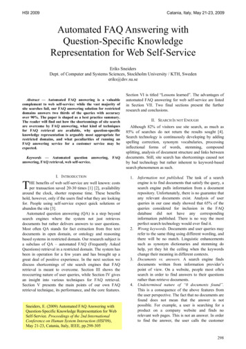
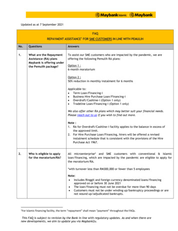
S7 communication between S7-200 and S7-300/400Entry-ID: 173695942S7 communication between S7-200 and S7-300/4002.1Configuration of a client connection in the S7-200In this example the S7-200 is configured as client for the S7communication, i.e. the S7-200 builds up active the S7 connection to theS7-300 and S7-400. The S7-300 and S7-400 are passive involved inestablishment of the S7 connection:Copyright Siemens AG 2008 All rights reservedS7 Komm S7300 en.docThe configuration is as follows: PLC 315-2DP (6ES7 315-2AG10-0AB0) and CP343-1 (6GK7 3431EX30-0XE0) PLC 416-2DP (6ES7 416-2XK02-0AB0) and CP443-1 (6GK7 4431GX11-0XE0) PLC 222 (6ES7212-1AB22-0XB0) and CP243-1 (6GK7 243-1EX000XE0)Figure 2-1 overview about the configurationserverS7-300 with CP343-1ip address: 140.80.0.50TSAP: 03.02S7 connection 1clientS7-200 with CP243-1ip address: 140.80.0.60local TSAP for S7 connection 1: 10.00local TSAP for S7 connection 2: 11.00SCALANCE X108serverS7-400 with C443-1ip address: 140.80.0.150TSAP: 03.03Snon7ctiec2onIn this example in the S7-200, S7-300 and S7-400 the following memoryarea are defined as send buffer and receive buffer.V1.115.08.20084/32
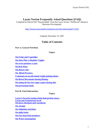
S7 communication between S7-200 and S7-300/400Entry-ID: 17369594Figure 2-2 send and receive buffer in the S7-200, S7-300 and 7-300write dataread dataDB20 Byte0 – DB20 Byte7DB20 Byte10 – DB20 Byte17S7-400DB30 Byte0 – DB30 Byte7DB30 Byte10 – DB30 Byte17Start STEP 7-MicroWIN in the Windows START Menu Æ SIMATIC ordouble-click the icon of the same name on the desktop.Copyright Siemens AG 2008 All rights reservedS7 Komm S7300 en.docOpen the Ethernet Wizard with the menu command „Tools Æ EthernetWizard “.Figure 2-3 opening the Ethernet WizardIn the first step of the Ethernet Wizard you will find a description of it. Clickthe button „Next“ to start with the configuration.V1.115.08.20085/32
S7 communication between S7-200 and S7-300/400Entry-ID: 17369594Copyright Siemens AG 2008 All rights reservedS7 Komm S7300 en.docFigure 2-4 description of the Ethernet WizardIf you have connected the SIMATIC Field PG to the CP243-1 overIndustrial Ethernet it will be possible the find out the module positionautomatically. Therefore click the button “Read Modules”. You can alsoenter the module position manually. Following click the button „Next“.Figure 2-5 find out the module positionV1.115.08.20086/32
S7 communication between S7-200 and S7-300/400Entry-ID: 17369594Enter a unique IP address for the CP243-1 and enter the correspondingsubnet mask. Click on the button „Next“ to apply the settings.Copyright Siemens AG 2008 All rights reservedS7 Komm S7300 en.docFigure 2-6 enter the IP address of the CP243-1In the following dialog you set the number of S7 connections which areconfigured for the CP243-1. Over one S7 connection you can read datafrom the communication partner and you can write data to thecommunication partner. Click the button “Next” to continue with theconfiguration of the S7 connection.V1.115.08.20087/32
S7 communication between S7-200 and S7-300/400Entry-ID: 17369594Copyright Siemens AG 2008 All rights reservedS7 Komm S7300 en.docFigure 2-7 setting the number of S7 connectionsConfigure a client connection to the S7-300In the example the first S7 connection is configured as client connection.For the remote parameter you enter the ip address of the server.The S7-300 with CP343-1 is the server for the first client connection. Theip address of the CP343-1 is 140.80.0.50 (see Figure 2-1 overview aboutthe configuration).The S7 connection between S7-200 and S7-300 is well-defined with theTSAPs. The client connection is one-sided configured in the S7-200. Youenter 03.02 for the remote TSAP. This TSAP means: 03: one-sided configured connection 02: slot of the PLC in the S7-300 (is always 2)Following click the button „Data Transfer“.V1.115.08.20088/32
S7 communication between S7-200 and S7-300/400Entry-ID: 17369594Copyright Siemens AG 2008 All rights reservedS7 Komm S7300 en.docFigure 2-8 configure client connection to the S7-300You have to choose the following function to write data in the S7-300:This data transfer should Write data to the remote server connectionEnter the number of data which should be written to the server. Here 8 bytedata (Variables Byte 0-7) are written to the S7-300. In the S7-300 thesedata are saved in DB20 (byte 0-7).Click the button „Next Transfer“ to read data from the S7-300.V1.115.08.20089/32
S7 communication between S7-200 and S7-300/400Entry-ID: 17369594Copyright Siemens AG 2008 All rights reservedS7 Komm S7300 en.docFigure 2-9 write data from the S7-300You have to choose the following function to read data from the S7-300:This data transfer should Read data from the remote server connectionEnter the number of data which should be read from the server. Here 8byte data (byte 10-17) are read from the DB20 in the S7-300. In the S7-200these data are saved in Variables Byte 10-17.Click the button „OK“ to apply the settings for the data transfer.V1.115.08.200810/32
S7 communication between S7-200 and S7-300/400Entry-ID: 17369594Copyright Siemens AG 2008 All rights reservedS7 Komm S7300 en.docFigure 2-10 read data from the S7-300Configure a client connection to the S7-400The second S7 connection is also configured as client connection.For the remote parameter you enter the ip address of the server.The S7-400 with CP443-1 is the server for the second client connection.The ip address of the CP443-1 is 140.80.0.150 (see Figure 2-1 overviewabout the configuration).The S7 connection between S7-200 and S7-400 is well-defined with theTSAPs. The client connection is one-sided configured in the S7-200. Youenter 03.03 for the remote TSAP. This TSAP means:NOTE 03: one-sided configured connection 03: slot of the PLC in the S7-400You find out the slot of the PLC from the hardware configuration of theS7-400 station.Following click the button „Data Transfer“.V1.115.08.200811/32
S7 communication between S7-200 and S7-300/400Entry-ID: 17369594Copyright Siemens AG 2008 All rights reservedS7 Komm S7300 en.docFigure 2-11 configure client connection to the S7-400You have to choose the following function to write data in the S7-400:This data transfer should Write data to the remote server connectionEnter the number of data which should be written to the server. Here 8 bytedata (Variables Byte 0-7) are written to the S7-400. In the S7-400 thesedata are saved in DB30 (byte 0-7).Click the button „Next Transfer“ to read data from the S7-400.V1.115.08.200812/32
S7 communication between S7-200 and S7-300/400Entry-ID: 17369594Copyright Siemens AG 2008 All rights reservedS7 Komm S7300 en.docFigure 2-12 write data to the S7-400You have to choose the following function to read data from the S7-400:This data transfer should Read data from the remote server connectionEnter the number of data which should be read from the server. Here 8byte data (byte 10-17) are read from the DB30 in the S7-400. In the S7-200these data are saved in Variables Byte 20-27.Click the button „OK“ to apply the settings for the data transfer.V1.115.08.200813/32
S7 communication between S7-200 and S7-300/400Entry-ID: 17369594Copyright Siemens AG 2008 All rights reservedS7 Komm S7300 en.docFigure 2-13 read data from the S7-400Since the configuration of the CP243-1 module may no longer be changed,you select the setting with CRC protection. You can specify the Keep AliveInterval with the default time. Click the button „Next“.V1.115.08.200814/32
S7 communication between S7-200 and S7-300/400Entry-ID: 17369594Copyright Siemens AG 2008 All rights reservedS7 Komm S7300 en.docFigure 2-14 CRC protection and KeepAlive IntervallSelect a free address area for storing the configuration.Figure 2-15 storing the configuration of the CP243-1Click on the button „Finish“ to close the Ethernet Wizard.V1.115.08.200815/32
S7 communication between S7-200 and S7-300/400Entry-ID: 17369594Copyright Siemens AG 2008 All rights reservedS7 Komm S7300 en.docFigure 2-16 finish the configuration of the CP243-1So the function blocks ETHx CTRL and ETHx XFR are created. You haveto call these function blocks in the main program (“MAIN (OB1)”) ofSTEP 7-MicroWIN.The function block ETHx CTRL is necessary for the communication setup.Figure 2-17 call ETH0 CTRLThe function block ETHx XFR is necessary to read and write the data. It scalled twice to read data from the S7-300 and write data to the S7-300 overthe first client connection.V1.115.08.200816/32
S7 communication between S7-200 and S7-300/400Entry-ID: 17369594Copyright Siemens AG 2008 All rights reservedS7 Komm S7300 en.docFigure 2-18 call ETH0 XFR to exchange data with S7-300Additional the function block „ETHx XFR“ is called twice to read data fromthe S7-400 and write data to the S7-400 over the second client connection.V1.115.08.200817/32
S7 communication between S7-200 and S7-300/400Entry-ID: 17369594Copyright Siemens AG 2008 All rights reservedS7 Komm S7300 en.docFigure 2-19 call ETH0 XFR to exchange data with S7-400Right click the input parameter „Chan ID“ and „Data“ of the function blockETHx XFR. So it’s possible to select the symbolic name directly.Save the configuration and download it in the PLC S7-200.2.2Configure the S7-300/400 as server for the S7 communicationIn the S7-300 and S7-400 which is the server for the S7 connection youonly need a data block (DB) with adequate length. The S7-200 reads thedata from this DB and writes the data to this DB, which is defined as sendand receive buffer respectively.In the S7-300 the DB20 is defined as send and receive buffer.In the S7-400 the DB30 is defined as send and receive buffer.It s not necessary to configure a S7 connection for the S7-300 and S7-400respectively in NetPro.V1.115.08.200818/32
S7 communication between S7-200 and S7-300/400Entry-ID: 17369594Furthermore it s not necessary to call any communication blocks in the S7program of the S7-300 and S7-400.Check the data transfer of S7 communicationIn STEP 7-MicroWIN open the program of the S7-200 and change to thestatus table. Here you can check and observe the receive buffer (VB10-17and VB20-17) of the S7-200 to find out if data are exchanged. Furthermoreit s possible to control the variables in the send buffer (VB0-7).Copyright Siemens AG 2008 All rights reservedS7 Komm S7300 en.docYou insert a variable table in the STEP 7 project of the S7-300 and S7-400respectively. With the variable table it s possible to observe the receivebuffer of the S7-300 and S7-400 and to control the variables in the sendbuffer of the S7-300 and S7-400.V1.115.08.200819/32
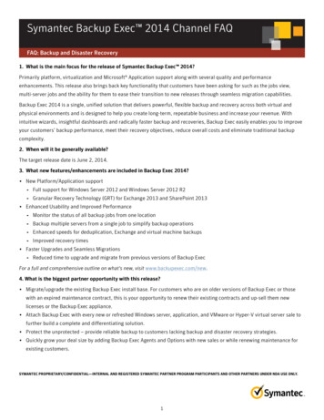
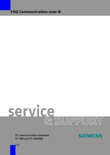
S7 communication between S7-200 and S7-300/400Entry-ID: 173695942.3Configuration of a server connection in the S7-200In this example the S7-200 is configured as server for the S7communication, i.e. the S7-300 and S7-400 build up active the S7connection to the S7-200. The S7-200 is passive involved in establishmentof the S7 connection:The configuration is as follows: PLC 315-2DP (6ES7 315-2AG10-0AB0) and CP343-1 (6GK7 3431EX30-0XE0) PLC 416-2DP (6ES7 416-2XK02-0AB0) and CP443-1 (6GK7 4431EX11-0XE0) PLC 222 (6ES7212-1AB22-0XB0) and CP243-1 (6GK7 243-1EX000XE0)Figure 2-20 overview about the configurationCopyright Siemens AG 2008 All rights reservedS7 Komm S7300 en.docclientS7-300 with CP343-1IP address: 140.80.0.50TSAP: 10.04serverS7-200 with CP243-1IP address: 140.80.0.60local TSAP for S7 connection 3: 12.00local TSAP for S7 connection 4: 13.00S7 connection 3SCALANCE X108Industrial EthernetclientS7-400 with CP443-1IP address: 140.80.0.150TSAP: 10.03S7nncotiecon4In this example in the S7-200, S7-300 and S7-400 the following memoryarea are defined as send buffer and receive buffer.Figure 2-21 send and receive buffer in the S7-200, S7-300 and S7-400clientserverS7-300DB20 Byte20 – DB20 Byte27DB20 Byte30 – DB20 Byte37S7-200read datawrite dataVB0-VB7VB30-VB37VB40-VB47S7-400DB30 Byte20 – DB30 Byte27DB30 Byte30 – DB30 Byte37V1.115.08.200820/32
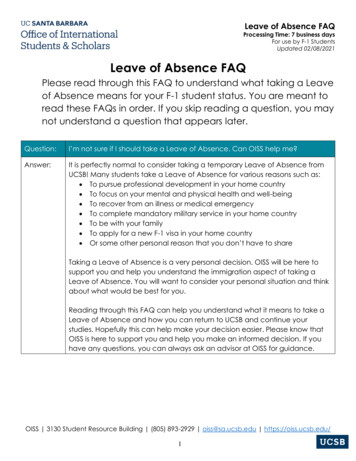
S7 communication between S7-200 and S7-300/400Entry-ID: 17369594Start STEP 7-MicroWIN in the Windows START Menu Æ SIMATIC ordouble-click the icon of the same name on the desktop.Open the Ethernet Wizard with the menu command „Tools Æ EthernetWizard “ (see Figure 2-3 opening the Ethernet Wizard).In the first step of the Ethernet Wizard you will find a description of it. Clickthe button „Next“ to start with the configuration.Copyright Siemens AG 2008 All rights reservedS7 Komm S7300 en.docFigure 2-22 description of the Ethernet WizardIf you have connected the SIMATIC Field PG to the CP243-1 overIndustrial Ethernet it will be possible the find out the module positionautomatically. Therefore click the button “Read Modules”. You can alsoenter the module position manually. Following click the button „Next“.V1.115.08.200821/32
S7 communication between S7-200 and S7-300/400Entry-ID: 17369594Copyright Siemens AG 2008 All rights reservedS7 Komm S7300 en.docFigure 2-23 find out the module positionEnter a unique IP address for the CP243-1 and enter the correspondingsubnet mask. Click on the button „Next“ to apply the settings.Figure 2-24 enter the IP address of the CP243-1V1.115.08.200822/32
S7 communication between S7-200 and S7-300/400Entry-ID: 17369594In the following dialog you set the number of S7 connections which areconfigured for the CP243-1. Over one S7 connection you can read datafrom the communication partner and you can write data to thecommunication partner. Click the button “Next” to continue with theconfiguration of the S7 connection.Copyright Siemens AG 2008 All rights reservedS7 Komm S7300 en.docFigure 2-25 setting the number of S7 connectionsConfigure a server connection to the S7-300In the example the third S7 connection is configured as server connection.The S7-300 with CP343-1 is the client for this server connection.The S7 connection has to be configured for the server (S7-200) and client(S7-300), i.e. the S7 connection is configured both-sided.The S7 connection between S7-200 and S7-300 is well-defined with theTSAPs. You enter 10.04 for the remote TSAP. This TSAP means:NOTE 10: both-sided configured connection 04: slot of the CP in the S7-300If you use a PLC S7-300 with integrated Industrial Ethernet interface youwill enter the slot of the PLC.Following you activate the function “Accept all connection requests.” andclick the button “Next Connection” to configure a further S7 connection.V1.115.08.200823/32
S7 communication between S7-200 and S7-300/400Entry-ID: 17369594Copyright Siemens AG 2008 All rights reservedS7 Komm S7300 en.docFigure 2-26 configure a server connection to S7-300Configure a server connection to the S7-400In the example the fourth S7 connection is configured as server connection.The S7-400 with CP443-1 is the client for this server connection.The S7 connection has to be configured for the server (S7-200) and client(S7-400), i.e. the S7 connection is configured both-sided.The S7 connection between S7-200 and S7-400 is well-defined with theTSAPs. You enter 10.03 for the remote TSAP. This TSAP means: 10: both-sided configured connection 03: slot of the PLC in the S7-400Following you activate the function “Accept all connection requests.” andclick the button “OK” to change to the next dialog.V1.115.08.200824/32
S7 communication between S7-200 and S7-300/400Entry-ID: 17369594Copyright Siemens AG 2008 All rights reservedS7 Komm S7300 en.docFigure 2-27 configure a server connection to the S7-400Since the configuration of the CP243-1 module may no longer be changed,you select the setting with CRC protection. You can specify the Keep AliveInterval with the default time. Click on the button “Next”.Figure 2-28 CRC protection and KeepAlive IntervallV1.115.08.200825/32
S7 communication between S7-200 and S7-300/400Entry-ID: 17369594Select a free address area for storing the configuration.Copyright Siemens AG 2008 All rights reservedS7 Komm S7300 en.docFigure 2-29 storing the configuration of the CP243-1Click on the button „Finish“ to close the Ethernet Wizard.Figure 2-30 finish the configuration of the CP243-1V1.115.08.200826/32
S7 communication between S7-200 and S7-300/400Entry-ID: 17369594So the function blocks ETHx CTRL and ETHx XFR are created. You haveto call these function blocks in the main program (“MAIN (OB1)”) ofSTEP 7-MicroWIN.The function block ETHx CTRL is necessary for the communication setup.Copyright Siemens AG 2008 All rights reservedS7 Komm S7300 en.docFigure 2-31 call ETH0 CTRLNOTEThe function block ETHx XFR only has to be call for the data transferover a client connection.Save the configuration and download it in the PLC S7-200.2.4Configure the S7-300/400 as client for the S7 communicationConfiguration of the S7 connectionThis example shows the configuration of a S7 connection for the S7-300.Use the same procedure for the S7-400.Open the STEP 7 project with the configuration of the S7-300. Followingopen the program NetPro with the menu command „OptionsÆConfigureNetwork“ or click on the corresponding symbol in the toolbarV1.115.08.200827/32
S7 communication between S7-200 and S7-300/400Entry-ID: 17369594Copyright Siemens AG 2008 All rights reservedS7 Komm S7300 en.docFigure 2-32 open NetProIn NetPro you select the CPU in the S7-300 station and add a newconnection with the menu command „Insert Æ New Connection.Figure 2-33Select for the connection partner „unspecified“ and for the connection type„S7 connection“. Click on the button „Apply”. The property view of the S7connection will open.V1.115.08.200828/32
S7 communication between S7-200 and S7-300/400Entry-ID: 17369594Copyright Siemens AG 2008 All rights reservedS7 Komm S7300 en.docFigure2-34 Insert New ConnectionV1.115.08.200829/32
S7 communication between S7-200 and S7-300/400Entry-ID: 17369594In the property view of the S7 connection you activate the function„Establish an active connection“, because the S7 connection is build up bythe S7-300. Enter the IP address of the CP243-1 for the Partner. Click onthe button “Address Details”.Copyright Siemens AG 2008 All rights reservedS7 Komm S7300 en.docFigure 2-35 property view of the S7 connectionIn the dialog „Address Details“ you enter the TSAP for the Partner, i.e.that’s the local TSAP of the S7-200 (in this example 12.0).Figure 2-36 Address DetailsV1.115.08.200830/32
S7 communication between S7-200 and S7-300/400Entry-ID: 17369594Select the S7-300 station in NetPro. Save and compile the configurationand download it in the S7-300 station.Calling the function blocks in the S7 programIt’s necessary to call function blocks FB14 “GET” and FB15 “PUT” in the S7program of the S7-300. These function blocks you find in Standard LibraryÆ Communication Blocks Æ Blocks.Copyright Siemens AG 2008 All rights reservedS7 Komm S7300 en.docFigure 2-37 calling FB14 “GET” und FB15 “PUT”Right click the input parameter „ID“ of the function blocks FB14 „GET“ andFB15 „PUT“ respectively, to insert the local ID of the connectionautomatically. You can also find out the local ID of the connection in theproperty view of the S7 connection (see Figure 2-35 property view of the S7connection).On the input parameter ADDR 1 of the function blocks FB14 „GET“ andFB15 „PUT“ you enter the area in the S7-200 which should be read andwrite respectively.The data are written in the area of Variables Bytes in the S7-200 and thedata are read from the area of Variables Bytes in the S7-200. The area ofVariables Bytes is addressed as DB1 by the S7-300.V1.115.08.200831/32
S7 communication between S7-200 and S7-300/400Entry-ID: 17369594NOTEIf you use a S7-400 you will need the function blocks SFB14 „GET“ andSFB15 „PUT“. These you find in the Standard Library Æ System FunctionBlocks Æ Blocks.Sample program FB14 „GET“ and FB15 „PUT“ for the S7-300You find a sample program with the function blocks FB14 “GET” and FB15“PUT” for the S7-300 in the following article: 18610307.Sample program SFB14 „GET“ and SFB15 „PUT“ for the S7-400You find a sample program with the function blocks SFB14 “GET” andSFB15 “PUT” for the S7-400 in the following article: 1819293.Copyright Siemens AG 2008 All rights reservedS7 Komm S7300 en.doc3HistoryVersionV1.1DateChangesV 1.022.04.2008first issueV1.115.08.2008complete revision15.08.200832/32
Start STEP 7-MicroWIN in the Windows START Menu Æ SIMATIC or double-click the icon of the same name on the desktop. Open the Ethernet Wizard with the menu command „Tools Æ Ethernet Wizard ". Figure 2-3 opening the Ethernet Wizard In the first step of the Ethernet Wizard you will find a description of it. Click