Transcription
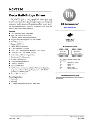
NCV7720Deca Half-Bridge DriverThe NCV7720 Deca is a ten channel half bridge driver withprotection features designed specifically for automotive and industrialmotion control applications. The product has independent controls anddiagnostics, and the drivers can be operated in forward, reverse, brake,and high impedance states. The device is controlled via a 16 bit SPIinterface and is daisy chain compatible.www.onsemi.comFeatures Low Quiescent Current Sleep Mode High Side and Low Side Drivers Connected in Half Bridge ConfigurationsIntegrated Freewheeling Protection (LS and HS)0.55 A Peak CurrentRDS(on) 1.0 W (typ)5 MHz SPI Communication16 Bit Frame Error DetectionDaisy Chain Compatible with Multiple of 8 bit DevicesCompliance with 3.3 V and 5 V SystemsUndervoltage and Overvoltage LockoutDiscriminated Fault ReportingOver Current ProtectionOver temperature ProtectionUnderload DetectionExposed Pad PackageNCV Prefix for Automotive and Other Applications RequiringUnique Site and Control Change Requirements; AEC Q100Qualified and PPAP CapableThis is a Pb Free DeviceSSOP24 NB EPCASE 940AKMARKING DIAGRAMNCV7720AWLYWWGNCV7720 orNCV7720AAWLYWWGNCV7720AAWLYWWG Specific Device Code Assembly Location Wafer Lot Year Work Week Pb Free PackageORDERING INFORMATIONTypical ApplicationsSee detailed ordering and shipping information on page 24 ofthis data sheet. Automotive Industrial DC Motor Management for HVAC Application Semiconductor Components Industries, LLC, 2016July, 2018 Rev. 71Publication Order Number:NCV7720/D
NCV7720NCV7720OUT1Low sideDriverVS113.2 VHigh ower 5Protection:Under LoadOver TemperatureUnder voltageOver voltageOver CurrentLSHSOUT6LSHSSO16 UT9LSHigh sideDriverLow sideDriverGNDFigure 1. Typical Applicationwww.onsemi.com2OUT10
NCV7720VS1DRIVE 1VSENENABLEHigh SideDriverVS1Wave e ShapingVSLow SideDriverSOSPILS Under Load16 Bit Logicand LatchFaultSISCLKCSBOvercurrentThermal Warning &ShutdownVS1VS2VS1, S2VS1VS1VS2VS2GNDGNDGNDGNDVS2Figure 2. Block T9DRIVE10OUT10
916VS2OUT61015OUT10OUT41114OUT3GND1213GNDFigure 3. Pinout – SSOP24PIN FUNCTION DESCRIPTION The pin out for the Deca Half Bridge in SSOP24 package is shown in the table lf bridge output 13OUT5Half bridge output 54OUT7Half bridge output 75SI6VCC16 bit serial communication input. 3.3V/5V (TTL) Compatible internally pulled down.7SO16 bit serial communication output. 3.3V/5V Compliant8ENEnable active high; wakes the device from sleep mode. 3.3V/5V (TTL) Compatible internally pulled down.9OUT9Half bridge output 910OUT6Half bridge output 611OUT4Half bridge output 412GNDGround13GNDGround14OUT3Half bridge output 315OUT10Half bridge output 10Power supply input for Logic.16VS217ReservedPower Supply input for outputs 3, 4, 6, 9, and 10. This pin must be connected to VS1 externally.Factory use connect to GND or leave unconnected internally pulled down.18ReservedFactory use connect to GND or leave unconnected internally pulled down.19CSBChip select bar active low; enables serial communication operation. 3.3V/5V (TTL) Compatible internallypulled up.20SCLKSerial communication clock input. 3.3V/5V (TTL) Compatible internally pulled down.21VS122OUT8Power Supply input for outputs 1, 2, 5, 7, 8, and all pre drivers. This pin must be connected to VS2 externally.Half bridge output 823OUT2Half bridge output 224GNDGroundEPADExposed PadConnect to GND or leave unconnected.www.onsemi.com4
NCV7720MAXIMUM RATINGS (Voltages are with respect to GND)RatingSymbolValueVSxdcMaxVSxac 0.3 to 40 1.0( Vcc, SI, SCLK, CSB, SO, EN)VioMax 0.3 to 5.5(DC)(AC)(AC), t 500 ms, IOUTx 1.1 A(AC), t 500 ms, IOUTx 1 AVoutxDcVoutxAc 0.3 to 40 0.3 to 40 1.01.0IoutxImax 2.0 to 2.0AJunction Temperature RangeTJ 40 to 150 CStorage Temperature RangeTstr 55 to 150 C(Note 1)260 CVSx Pin VoltageI/O Pin Voltage(VS1, VS2)(DC)(AC), t 500 ms, Ivsx 2 AUnitVVOUTx Pin VoltageOUTx Pin CurrentV(OUT1, ., OUT10)Peak Reflow Soldering Temperature: Pb free 60 to 150 seconds at 217 CStresses exceeding those listed in the Maximum Ratings table may damage the device. If any of these limits are exceeded, device functionalityshould not be assumed, damage may occur and reliability may be affected.1. See or download ON Semiconductor’s Soldering and Mounting Techniques Reference Manual, SOLDERRM/D.ATTRIBUTESCharacteristicShort Circuit Reliability CharacterizationESD CapabilityHuman Body Model per AEC Q100 002VSx, OUTxAll Other PinsMachine Model per AEC Q100 003Moisture Sensitivity LevelPackage Thermal Resistance – Still te 2)(Note 3)(Note 2)(Note 3)SymbolValueUnitAECQ10xGrade A Vesd4kVesd2kVesd200 4.0 kV 2.0 kV 200 VMSLMSL2 RqJARqJA54262214 C/W C/W C/W C/WRYJBOARDRYJBOARD2. Based on JESD51 3, 1.2 mm thick FR4, 2S0P PCB with 2 oz. copper and 18 thermal vias to 600 mm2 spreader on bottom layer.3. Based on JESD51 7, 1.2 mm thick FR4, 1S2P PCB with 2 oz. copper and 18 thermal vias to 80x80 mm 1 oz. internal spreader planes.RECOMMENDED OPERATING CONDITIONSSymbolMinMaxUnitDigital Supply Input VoltageParameterVCCOp3.155.25VBattery Supply Input VoltageVSxOp5.528VDC Output CurrentIxOp 0.55AJunction TemperatureTjOp 40125 CFunctional operation above the stresses listed in the Recommended Operating Ranges is not implied. Extended exposure to stresses beyondthe Recommended Operating Ranges limits may affect device reliability.www.onsemi.com5
NCV7720ELECTRICAL CHARACTERISTICS( 40 C TJ 150 C, 5.5 V VSx 40 V, 3.15 V VCC 5.25 V, EN VCC, unless otherwise Unit 1.02.5mA 2.55.0mA 1.02.5mA 1.53.0mASleep Mode, 40 C to 85 CVS1 VS2 13.2 V, No Load 2.05.0mAPOWER SUPPLIESSupply Current (VS1 VS2)Sleep ModeIqVSx85Supply Current (VS1 VS2)Active ModeIvsOpSupply Current (Vcc)Sleep ModeActive ModeTotal Sleep Mode CurrentI(VS1) I(VS2) I(VCC)IqVCCIVCCOpIqTotVS1 VS2 13.2V, VCC 0 V 40 C to 85 CEN VCC, 5.5V VSx 28 VNo LoadCSB VCC, EN SI SCLK 0 V 40 C to 85 CEN CSB VCC, SI SCLK 0VNo LoadVCC Power on Reset ThresholdVCCporVCC increasing 2.552.90VVSx Undervoltage Detection ThresholdVSxuvVSx decreasing3.54.14.5V100 450mV303640V12.54VVSx Undervoltage DetectionHysteresisVSxuHysVSx Overvoltage Detection ThresholdVsXovVSx Overvoltage Detection HysteresisVSxoHysVSx increasingDRIVER OUTPUT CHARACTERISTICSOutput High RDS(on) (source)RDSonHSIout 500 mA, Vs 13.2 VVCC 3.15 V 1.02.25WOutput Low RDS(on) (sink)RDSonLSIout 500 mA, Vs 13.2 VVCC 3.15 V 1.02.25WOutput Path RDS(HSx LSx)RDSonPathIout 500 mA, TJ 125 C 4.0WVCC 5 V,OUT(1 10) 0 V, 40 C to 85 C;VSx 13.2 VVSx 28 V 1.0 2.0 mAmAVCC 5 V;OUT(1 10) VSx 13.2 VOUT(1 10) VSx 28 V 1.02.0mAmASource Leakage CurrentSink Leakage rcurrent Shutdown Threshold(Source)IsdSrcVCC 5 V, VSx 13.2 V 2.0 1.2 0.8AOvercurrent Shutdown Threshold(Sink)IsdSnkVCC 5 V, VSx 13.2 V0.81.22.0A102550msOver Current Delay TimerTdOcUnderload Detection Threshold(Low Side)IuldLSVCC 5 V, VSx 13.2 V2.01120mAUnderload Detection Delay TimeTdUldVCC 5 V, VSx 13.2 V200350600msIf 500 mA 0.91.3VBody Diode Forward VoltageIbdFwdDRIVER OUTPUT SWITCHING CHARACTERISTICSHigh Side Turn On TimeThsOnVs 13.2 V, Rload 39 W 7.513msHigh Side Turn Off TimeThsOffVs 13.2 V, Rload 39 W 3.06.0msLow Side Turn On TimeTlsOnVs 13.2 V, Rload 39 W 6.513msLow Side Turn Off TimeTlsOffVs 13.2 V, Rload 39 W 2.05.0msProduct parametric performance is indicated in the Electrical Characteristics for the listed test conditions, unless otherwise noted. Productperformance may not be indicated by the Electrical Characteristics if operated under different conditions.4. Not production tested.5. This is the minimum time the user must wait between SPI commands.6. This is the minimum time the user must wait between consecutive SRR requests.www.onsemi.com6
NCV7720ELECTRICAL CHARACTERISTICS( 40 C TJ 150 C, 5.5 V VSx 40 V, 3.15 V VCC 5.25 V, EN VCC, unless otherwise UnitDRIVER OUTPUT SWITCHING CHARACTERISTICSHigh Side Rise TimeThsTrVs 13.2 V, Rload 39 W 4.08.0msHigh Side Fall TimeThsTfVs 13.2 V, Rload 39 W 2.04.0msLow Side Rise TimeTlsTrVs 13.2 V, Rload 39 W 1.03.0msLow Side Fall TimeTlsTfVs 13.2 V, Rload 39 W 1.03.0msHigh Side Off to Low Side OnNon Overlap TimeThsOffLsOnVs 13.2 V, Rload 39 W1.5 msLow Side Off to High Side OnNon Overlap TimeTlsOffHsOnVs 13.2 V, Rload 39 W1.5 msTwr(Note 4)120140170 CTwHy(Note 4) 20 CTsd(Note 4)150175200 CTsdHy(Note 4) 20 CVthInHVthInL2.0 0.6VVInput Hysteresis SI, SCLK, CSBVthInHys50150300mVInput Hysteresis ENVthENHys150400800mVEN SI SCLK VCC50125200kWCSB 0 V50125250kWCinx(Note 4) 15pFOutput HighVsoHISOURCE 1 mAVCC –0.6 VOutput LowVsoLISINK 1.6 mA 0.4VTHERMAL RESPONSEThermal WarningThermal Warning HysteresisThermal ShutdownThermal Shutdown HysteresisLOGIC INPUTS EN, SI, SCLK, CSBInput ThresholdHighLowPull down Resistance EN, SI, SCLKPull up Resistance CSBInput CapacitanceRpdxRpuCSBLOGIC OUTPUT SOTri state LeakageItriStLkgCSB 5 V 5 5mATri state Output CapacitanceItriStCoutCSB VCC, 0 V VCC 5.25 V(Note 4) 15pFTimingCharts #MinTypMaxUnit 5.0MHz 200500 nsSERIAL PERIPHERAL INTERFACECharacteristicSCLK FrequencySymbolConditionsFclkVCC 5 VVCC 3.3 VSCLK Clock PeriodTpClkSCLK High TimeTclkH185 nsSCLK Low TimeTclkL285 nsSCLK Setup TimeTclkSup3, 485 nsSI Setup TimeTsiSup1150 nsSI Hold TimeTsiH1250 nsProduct parametric performance is indicated in the Electrical Characteristics for the listed test conditions, unless otherwise noted. Productperformance may not be indicated by the Electrical Characteristics if operated under different conditions.4. Not production tested.5. This is the minimum time the user must wait between SPI commands.6. This is the minimum time the user must wait between consecutive SRR requests.www.onsemi.com7
NCV7720ELECTRICAL CHARACTERISTICS( 40 C TJ 150 C, 5.5 V VSx 40 V, 3.15 V VCC 5.25 V, EN VCC, unless otherwise specified.)SERIAL PERIPHERAL s #MinTypMaxUnit5, 6100 ns75.0 msCSB Setup TimeTcsbSupCSB High TimeTcsbHSO enable after CSB falling edgeTenSo8 200nsSO disable after CSB rising edgeTdisSo9 200nsSO Rise/Fall TimeTsoR/FCload 40 pF (Note 4) 1025nsSO Valid TimeTsoVCload 40 pF (Note 4)SCLK to SO 50%10 2050nsEN Low Valid TimeTenLVCC 5V; EN H L 50%to OUTx turning off 50% 10 ms 100ms 150 msEN High to SPI ValidSRR Delay Between ConsecutiveFrames(Note 5)TenHspiVTsrr(Note 6)Product parametric performance is indicated in the Electrical Characteristics for the listed test conditions, unless otherwise noted. Productperformance may not be indicated by the Electrical Characteristics if operated under different conditions.4. Not production tested.5. This is the minimum time the user must wait between SPI commands.6. This is the minimum time the user must wait between consecutive SRR requests.www.onsemi.com8
NCV7720CHARACTERISTIC TIMING DIAGRAMSTlsTr90%TlsOff10%LS Turn OFFTlsOffHsOn90%10%HS Turn ONThsTr90%ThsOnCSBLS Turn OnTlsTf90%TlsOn10%HS Turn OffThsOffLsOn90%10%ThsTf90%ThsOffCSBFigure 4. Detailed Driver Timingwww.onsemi.com9
NCV772047CSB5SCLK3126CSBSO98SI12SCLK1011SOFigure 5. Detailed SPI Timingwww.onsemi.com10
NCV7720TYPICAL PERFORMANCE CURVES2.3ACITVE MODE VCC CURRENT (mA)6.0SLEEP MODE CURRENT (mA)VSx 13.2 V5.04.03.0VCC 5.25 V2.0VCC 5 V1.00 50VCC 3.15 V 30 101030507090110 130 1502.225 C2.1 40 C2.12.03.03.54.04.55.0Figure 7. I(VCC) Active Mode vs. V(VCC)BODY DIODE FORWARD VOLTAGE (V)1.6RDS(on) (W)125 CFigure 6. IqTot vs. Temperature1.8HSx1.4LSx1.21.00.80501001505.51.2If 0.5 A1.11.0LSxHSx0.90.8 50050100150TEMPERATURE ( C)TEMPERATURE ( C)Figure 8. RDS(on) vs. TemperatureFigure 9. Body Diode Voltage vs. Temperature2.00.201.5LSx1.00.50 0.5 1.0HSx 1.5VS 13.2 V,VCC 5.0 V050100IsrcLkg, IsnkLkg, LEAKAGE CURRENT(mA)IsdSrc, IsdSnk, OVERCURRENT (A)2.2VCC VOLTAGE (V)VSx 13.2 V 2.0 50150 CTEMPERATURE ( C)2.00.6 50VSx 13.2 V2.3150LSx0 0.20HSx 0.40 0.60 0.80 1.00 1.20VSx 13.2 V 1.40 50050100TEMPERATURE ( C)TEMPERATURE ( C)Figure 10. Over Current vs. TemperatureFigure 11. Leakage Current vs. Temperaturewww.onsemi.com11150
NCV7720DETAILED OPERATING DESCRIPTIONGeneral OverviewSPI CommunicationThe NCV7720 is comprised of twenty power drivers (10PMOS high side and 10 NMOS low side). The drivers arearranged as ten half bridge output channels, allowing forfive independent full bridge configured loads. Outputcontrol and status reporting is handled via the SPI (SerialPeripheral Interface) communications port.Each output is characterized for a maximum 0.55 A DCload and has a maximum 2.0 A surge capability (at VSx 13.2 V). Maximum allowable junction temperature is 150 Cand may constrain the maximum load current and/or limitthe number of drivers active at once.An active high enable function (EN) allows globalcontrol of the outputs and provides a low quiescent currentsleep mode when the device is not being utilized. An internalpull down resistor is provided on the input to ensure thedevice enters sleep mode if the input signal is lost.When EN is asserted, the VCC POR cycle will proceed andbring the device into normal operation. The deviceconfiguration registers can then be programmed via SPI.De asserting EN clears all registers (no configuration orstatus data is stored), resets the drivers, and enters sleepmode.16 bit full duplex SPI communication has beenimplemented for device configuration, driver control, andreading the status data. In addition to the 16 bit status data,a pseudo bit (PRE 15) can also be retrieved from the SOoutput.The device must be enabled (EN H) for SPIcommunication. The SPI inputs are TTL compatible and theSO output high level is defined by the applied VCC. Theactive low CSB input has a pull up resistor and theremaining inputs have pull down resistors to bias them toknown states when the SPI is not active.The latched thermal shutdown (TSD) status bit PRE 15is available on SO until the first rising SCLK edge after CSBgoes low. The following conditions must be met for a validTSD read to be captured:1. SCLK and SI are low before the CSB cycle;2. CSB transitions from high to low;3. CSB setup time (TcsbSup: Figure 5, #5) issatisfied.Figure 12 shows the SPI communication frame format,and Tables 1 and 2 define the command input and diagnosticstatus output bits.CSBSISRRSCLKSO15TSDPRE 15PSEUDO 15OCSHBSEL14PSFB[12:7 HBEN[6:1]B[10:7] HBEN[10:7]ULDSCB[6 :1 ] ³ HBCNF [6: 1]B[ 4:1 ] ³ HBCNF [10 :7 ]13OVLO0ULDB[ 12: 7] ³ HBST [6 :1]B [10 :7] ³ HBST [ 10: 7]B [6: 1] ³ HBCR [ 6:1 ]B[4 :1] ³ HBCR [10 :7]TWFigure 12. SPI Communication Frame Format5. Current SO data is simultaneously shifted out onevery rising edge of SCLK, starting with the MSB(OCS).6. CSB goes high to end the frame and SO becomestri state.7. The last 16 bits clocked into SI are transferred tothe device’s data register if no frame error isdetected, otherwise the entire frame is ignored andthe previous input data is preserved.Communication is implemented as follows and is alsoillustrated in Figures 12 and 14:1. SI and SCLK are set to low before the CSB cycle.2. CSB goes low to begin a serial data frame;pseudo bit PRE 15 is immediately available atSO.3. SI data is shifted in on every rising edge of SCLK,starting with the most significant bit (MSB), SRR.4. SI data is recognized on every falling edge of theSCLK.www.onsemi.com12
NCV7720Table 1. SPI COMMAND INPUT DEFINITIONSChannels 10 – 7 (Input Bit # 14 1)Bit#NameFunctionStatus*Scope15SRRStatus Register Reset**1 ResetStatus Reset per HBSEL14HBSELChannel Group Select1 HB [10:7]1 HB [10:7] 0 HB [6:1]13ULDSCUnderload Shutdown1 EnabledEnabled per HBSEL;Per Half Bridge OperationXNot Used 10HBEN10Enable Half Bridge 109HBEN9Enable Half Bridge 90 Hi Z8HBEN8Enable Half Bridge 81 Enabled7HBEN7Enable Half Bridge 7XNot Used4HBCNF10Configure Half Bridge 103HBCNF9Configure Half Bridge 90 LS On, HS Off2HBCNF8Configure Half Bridge 81 LS Off, HS On1HBCNF7Configure Half Bridge 70OVLOVSx Overvoltage Lockout1211Per Half Bridge65 Per Half Bridge1 EnabledGlobal LockoutChannels 6 – 1 (Input Bit # 14 0)Bit#NameFunctionStatus*Scope15SRRStatus Register Reset**1 ResetStatus Reset per HBSEL14HBSELChannel Group Select0 HB [6:1]1 HB [10:7] 0 HB [6:1]13ULDSCUnderload Shutdown1 EnabledEnabled per HBSEL;Per Half Bridge Operation12HBEN6Enable Half Bridge 611HBEN5Enable Half Bridge 510HBEN4Enable Half Bridge 40 Hi Z9HBEN3Enable Half Bridge 31 Enabled8HBEN2Enable Half Bridge 27HBEN1Enable Half Bridge 16HBCNF6Configure Half Bridge 65HBCNF5Configure Half Bridge 54HBCNF4Configure Half Bridge 40 LS On, HS Off3HBCNF3Configure Half Bridge 31 LS Off, HS On2HBCNF2Configure Half Bridge 21HBCNF1Configure Half Bridge 10OVLOVSx Overvoltage LockoutPer Half BridgePer Half Bridge1 Enabled*All command input bits are set to 0 at VCC power on reset.**Latched faults are cleared and outputs can be re programmed if no fault exists after SRR asserted.www.onsemi.com13Global Lockout
NCV7720Table 2. SPI STATUS OUTPUT DEFINITIONSChannels 10 – 7 (Input Bit # 14 1)Bit#NameFunctionStatus*ScopePRE 15TSDLatched Thermal Shutdown1 FaultGlobal Notification;Per Half Bridge Operation15OCSLatched OvercurrentShutdown1 FaultNotification per HBSEL;Per Half Bridge Operation14PSFVS1 and/or VS2Undervoltage or Overvoltage1 FaultGlobal Notification andGlobal Operation13ULDUnderload Detect1 FaultNotification per HBSEL;Per Half Bridge OperationXNot Used(Hard coded to zero) 10HBST10Half Bridge 10 Output Status9HBST9Half Bridge 9 Output Status0 Hi Z8HBST8Half Bridge 8 Output Status1 Enabled7HBST7Half Bridge 7 Output StatusXNot Used4HBCR10Half Bridge 10 Config Status3HBCR9Half Bridge 9 Config Status0 LS On, HS Off2HBCR8Half Bridge 8 Config Status1 LS Off, HS On**1HBCR7Half Bridge 7 Config Status0TWThermal Warning1211Per Half Bridge65(Hard coded to zero) Per Half Bridge1 Fault*All status output bits are set to 0 at Vcc power on reset (POR).**HBCRx is forced to 0 when HBSTx 0 via POR, SPI, or fault.www.onsemi.com14Global Notification;Per Half Bridge Operation
NCV7720Table 2. SPI STATUS OUTPUT DEFINITIONSChannels 6 – 1 (If Previous Input Bit # 14 0)Bit#NameFunctionStatus*ScopePRE 15TSDLatched Thermal Shutdown1 FaultGlobal Notification;Per Half Bridge Operation15OCSLatched OvercurrentShutdown1 FaultNotification per HBSEL;Per Half Bridge Operation14PSFVS1 and/or VS2Undervoltage or Overvoltage1 FaultGlobal Notification andGlobal Operation13ULDUnderload Detect1 FaultNotification per HBSEL;Per Half Bridge Operation12HBST6Half Bridge 6 Output Status11HBST5Half Bridge 5 Output Status10HBST4Half Bridge 4 Output Status0 Hi Z9HBST3Half Bridge 3 Output Status1 Enabled8HBST2Half Bridge 2 Output Status7HBST1Half Bridge 1 Output Status6HBCR6Half Bridge 6 Config Status5HBCR5Half Bridge 5 Config Status4HBCR4Half Bridge 4 Config Status0 LS On, HS Off3HBCR3Half Bridge 3 Config Status1 LS Off, HS On**2HBCR2Half Bridge 2 Config Status1HBCR1Half Bridge 1 Config Status0TWThermal WarningPer Half BridgePer Half Bridge1 FaultGlobal Notification;Per Half Bridge Operation*All status output bits are set to 0 at Vcc power on reset (POR).**HBCRx is forced to 0 when HBSTx 0 via POR, SPI, or fault.Frame Error Detectiondevice’s SI. The SO of the final device in the chain isconnected to the master’s MISO.The hardware configuration for the NCV7720 daisychained with an 8 bit SPI device is shown in Figure 13. A24 bit frame made of 16 bit word ‘A’ and 8 bit word ‘B’ issent from the master. Command word B is sent first followedby word A. The master simultaneously receives status wordB first followed by word A. The progression of data from theMCU through the sequential devices is illustrated inFigure 14.Compliance with the illustrated frame format is requiredfor proper daisy chain operation. Situations should beavoided where an incorrect multiple of 8 bits is sent to thedevices, but the frame length does not cause a frame error inthe devices. For example, the word order could beinadvertently interleaved or reversed. Invalid data isaccepted by the NCV7720 in such scenarios and possibly byother devices in the chain, depending on their frame errorimplementation. Data is received as a command by thedevice at the beginning of the chain, but the device at the endof the chain may receive status data from the precedingdevice as a command.The NCV7720 employs frame error detection to helpensure input data integrity. SCLK is compared to an n x 8 bitcounter and a valid frame (CSB H L H cycle) has integermultiples of 8 SCLK cycles. For the first 16 bits shifted intoSI, SCLK is compared to a modulo16 counter (n 2), andSCLK is compared to a modulo 8 counter (n 1, 2, .m)thereafter. This variable modulus facilitates daisy chainoperation with devices using different word lengths.The last 16 bits clocked into SI are transferred to theNCV7720’s data register if no frame error is detected,otherwise the entire frame is ignored and the previous inputdata is preserved.Daisy Chain OperationDaisy chain operation is possible with multiple 16 bit and8 bit devices that have a compatible SPI protocol. The clockphase and clock polarity with respect to the data for all thedevices in the chain must be the same as the NCV7720.CSB and SCLK are parallel connected to every device inthe chain while SO and SI are series connected between eachdevice.The master’s MOSI is connected to the SI of the firstdevice and the first device’s SO is connected to the nextwww.onsemi.com15
NCV7720CMD [x, n] Command Word to Device ‘x’, Length ‘n’STA [x, n] Status Word from Device ‘x’, Length ‘n’MCUMISONCV77208 bit Device16 bit DeviceCSBCSBCSBSCLKSCLKSCLKMOSIMasterSOSICMD [B, 8] CMD [A, 16]SOSISTA [A, 16] CMD[B, 8]Device ASTA [B, 8] STA [A, 16]Device BFigure 13. Daisy Chain Configuration24bit FrameWord B 8 bitsWord A 16 bitsCSBSCLK7610MSBSI15LSB870MSBLSBMSBLSBSI data is recognized on the falling SCLK. edgeSOTSDMSBLSBSO data is shifted out on the rising SCLK edge.Modulo 16 counter begins on the first rising SCLK edge after CSB goes low.Modulo 16 counter ends 16 bit word length valid.Modulo 8 counter begins on the next rising SCLK edge.Modulo 8 counter ends 8 bit word length valid. valid n*8 bit frame.Figure 14. Daisy Chain – 24 bit Frame FormatTSD Bit in Daisy Chain OperationThe TSD status automatically propagates through thechain from the SO output of the previous device to the SIinput of the next. This is shown in Figures 16 and 17, firstwithout a TSD fault in either device (Figure 16), and thensubsequently with a latched TSD fault (TSD 1) in device“A” propagating through to device “B” (Figure 17).Since the TSD status of any device propagatesautomatically through the entire chain, it is not possible todetermine which device (or devices) has a fault (TSD 1).The usual status data from each device will need to beexamined to determine where a fault (or faults) may exist.The SO path is designed to allow TSD status retrieval ina daisy chain configuration using NVC7720 or other deviceswith identical SPI functionality. The TSD status bit is OR’dwith SI and then multiplexed with the device’s usual statusdata (Figure 15).CSB is held high and SI and SCLK are held low by themaster before the start of the SPI frame. TSD status isimmediately available as bit PRE 15 at SO (SO TSD)when CSB goes low to begin the frame. The usual status data(SO STA) becomes available after the first rising SCLKedge.www.onsemi.com16
NCV7720SIMUXTSDSOSOSISPISELFigure 15. TSD SPI LinkNCV7720MCUMISONCV7720or � 0SIDevice ADevice BNo TSDNo TSDSOZ³ 0SOZ³1Figure 16. Daisy Chain Without TSD FaultNCV 7720MCUMISOMasterNCV7720or NCV7718CSB1³0CSBCSBSCLK0SCLKSCLKMOSI0SISOZ³ 1SIDevice ADevice BLatched TSDNo TSDFigure 17. Daisy Chain With TSD FaultPower Up/Down ControlDriver ControlThe VCC supply input powers the device’s logic core. AVCC power on reset (POR) function provides controlledpower up/down. VCC POR initializes the command inputand status output registers to their default states (0x00), andensures that the bridge output and SO drivers maintain Hi Zas power is applied. SPI communication and normal deviceoperation can proceed once VCC rises above the PORthreshold.The VS1 and VS2 supply inputs power their respectiveoutput drivers (refer to Figure 2 and the PIN FUNCTIONDESCRIPTION). The VSx inputs are monitored to ensurethat the supply stays within the recommended operatingrange. If the VSx supply moves into either of the VSundervoltage or overvoltage regions, the output drivers areswitched to Hi Z but command and status data is preserved.The NCV7720 has the flexibility to control eachhalf bridge driver channel via SPI. Actual driver outputstate is determined by the command input and the currentfault status bits as shown in Figure 18 and Table 3.The channels are divided into two groups and each groupis selected by the HBSEL input bit (see Table 1). High side(HSx) and low side (LSx) drivers of the same channelcannot be active at the same time, and non overlap delaysare imposed when switching between HSx and LSx driversin the same channel. This control design thus preventscurrent shoot through.After the device has powered up and the drivers areallowed to turn on, the drivers remain on until commandedoff via SPI or until a fault condition occurs.www.onsemi.com17
NCV7720VSHSxHBCNFxOUTxHBENxLSxHBCRxGNDPSF VSUVPSF VSOVHBSTxSPI OVLOSPI ULDSCQRSLATCHSRRCONTROLULDOCS(reset dominant)TSDFAULTSPIFigure 18. Simplified Half Bridge Control LogicTable 3. OUTPUT STATE VS. COMMAND AND X00Z1010GND1111VSwww.onsemi.com18
NCV7720DIAGNOSTICS, PROTECTIONS, STATUS REPORTING AND RESETOverviewintervention for output recovery and status memory clear.Diagnostics resulting in output lockout and non latchedstatus (VSOV or VSUV) may recover and clearautomatically. Output configurations can be changed duringoutput lockout. Outputs assume the new configurations orresume the previous configurations when an auto recoverfault is resolved. Table 5 shows output states during faultsand output recovery modes, and Table 6 shows the statusmemory and memory clear modes.The NCV7720 employs diagnostics designed to preventdestructive overstress during a fault condition. Diagnosticsare classified as either supervisory or protection functions(Table 4). Supervisory functions provide status informationabout device conditions. Protection functions provide statusinformation and activate fault management behaviors.Diagnostics resulting in output shutdown and latchedstatus may depend on a qualifier and may require userTable 4. Diagnostic Classes and FunctionsNameClassFunctionTSDProtectionThermal ShutdownOCSProtectionOvercurrent ShutdownPSFSupervisoryUnder/overvoltage LockoutULDProtectionUnderload ShutdownHBSTXSupervisoryHalf Bridge X Output StatusHBCRXSupervisoryHalf Bridge X Config StatusTWSupervisoryThermal WarningTable 5. OUTPUT STATE VS. FAULT AND OUTPUT RECOVERYFaultQualifierOUTxStateOUTxRecoveryTSD ZSend SRROCS ZSend SRRPSF – VSOVOVLO 1 Z Yn Yn 1Auto*OVLO 0Unaffected PSF – VSUV Z Yn Yn 1Auto*ULDULDSC 1 ZSend SRRULDSC 0Unaffected Unaffected TW*OUTx returns to its previous state (Yn) or new state (Yn 1) if fault is removed.Table 6. STATUS MEMORY VS. FAULT AND MEMORY CLEARFaultQualifierStatusMemoryMemoryClearTSD LatchedSend SRROCS LatchedSend SRRPSF – VSOVOVLO XNon LatchedAuto*PSF – VSUV Non LatchedAuto*ULDULDSC XLatchedSend SRRTW Non LatchedAuto**Status memory returns to its no fault state if fault is removed.www.onsemi.com19
NCV7720Status Information RetrievalDiagnostics DetailsCurrent status information as selected by HBSEL isretrieved during each SPI frame. To preserve deviceconfiguration and output states, the previous SI data patternmust be sent during the status retrieval frame.Status information is prevented from being updatedduring a SPI frame but new status becomes available afterCSB goes high at the end of the frame provided the frame didnot contain an SRR request. For certain device faults, it maynot be possible to determine which channel (or channels) hasa particular fault (or faults) since notification may be via asingle global status bit. The complete status data from allchannels may need to be examined to determine where afault may exist.The following sections describe the individualdiagnostics and some behaviors. In each description andillustration, a SPI frame is assumed to always be valid andthe SI data pattern sent for HBCNFx and HBENx is the sameas the previous frame. Actual results can depend onasynchronous fault events and SPI clock frequency andframe rate.Undervoltage LockoutGlobal Notification, Global OperationUndervoltage detection and lockout control is providedby monitoring the VS1, VS2 and VCC supply inputs.Undervoltage hysteresis is provided to ensure cleandetection transitions. Undervoltage timing is shown inFigure 19.Undervoltage at either VSx input turns off all outputs andsets the power supply fail (PSF) status bit. The outputs returnto their previously programmed state and the PSF status bitis cleared when VSx rises above the hysteresis voltage level.SPI is
1 Publication Order Number: NCV7720/D NCV7720 Deca Half-Bridge Driver . Low Quiescent Current Sleep Mode . A Assembly Location WL Wafer Lot Y Year WW Work Week G Pb Free Package SSOP24 NB EP CASE 940AK NCV7720A AWLYWWG. NCV7720 www.onsemi.com 2