Transcription
Rensselaer Polytechnic InstituteNetwork & Telecommunications DepartmentDivision 25100 Design Guidelines and SpecificationsJanuary 30, 2004
Rensselaer Polytechnic InstituteNetwork and Telecommunications DepartmentDesign Guidelines Table of Contents1DEFINITION OF TERMS, ACRONYMS AND ABBREVIATIONS. 52DESIGN GUIDELINES . 7325110TELECOMMUNICATIONS ROOMS . 8425120EQUIPMENT ROOMS AND SERVICE ENTRANCES . 13525130INTERIOR COMMUNICATIONS PATHWAYS . 13625140EXTERIOR COMMUNICATIONS PATHWAYS. 15725150BACKBONE CABLING. 20825160HORIZONTAL CABLING. 20925170TESTING, IDENTIFICATION AND ADMINISTRATION . 2210CSI 3 PART FORMATTED SPECIFICATIONS . 2211List of figures121314Figure 1 – Example of a Telecommunications Room . 8Figure 2 – Example of a Maintenance Hole. 18Figure 3 – Example of a Handhole . 19ii
Rensselaer Polytechnic InstituteNetwork and Telecommunications DepartmentGeneral1Rensselaer Polytechnic Institute Information Technology’s Infrastructure Design Guideline is intendedto be used in conjunction with CSI Formatted 3 part Division 25100 Specifications and T seriesdrawings and to be incorporated into RENSSELAER POLYTECHNIC INSTITUTE construction projectspecifications.The purpose of the Design Guidelines is to describe and specify the minimum building infrastructurerequired to support the communications and networking requirements at Rensselaer PolytechnicInstitute. Architects, engineers and designers should use these Design Guidelines to incorporate theinformation provided into Construction Documents. This document is based on industry standardsand codes. This document does not replace any national or local standards, regulations or codes, butenhances them. If the standards and practices of Rensselaer Polytechnic Institute exceed national orlocal standards, regulations or codes, Rensselaer Polytechnic Institute’s practices shall takeprecedent.The scope of this document includes the design and installation methods of TelecommunicationRooms (TR’s), cabling distributions systems and work area outlet locations, cable specifications,testing, documentation and administration. For details on products and installation practices forcommunications cabling and components refer to the Division 25100 Specifications. This document issubject to change in form and technical content as warranted by advancements in buildingconstruction techniques and telecommunications technology. As such, Rensselaer PolytechnicInstitute specifically reserves the right to add to and revise, the information contained herein.2Normative referencesThe following codes and standards contain provisions that, through reference in this text, constituteprovisions of Document. At the time of publication, the editions indicated were valid. All codes andstandards are subject to revision; parties to agreements based on this Document shall apply the mostrecent editions of the codes standards indicated. All equipment, construction practices, designprinciples and installations must conform to the latest version of any or all of the following standardsand codes, published by the following organizations, where applicable;Federal Communications Commission (FCC)Institute of Electrical and Electronics Engineers, Inc (IEEE)National Fire Protection Association (NFPA)National Electrical Safety Code (NESC)American National Standards Institute (ANSI)Telecommunications Industry Association (TIA)Electronic Industries Alliance (EIA)Building Industry Consulting Service International (BICSI)National Electrical Contractors Association (NECA)Reference Documentation345678910All RENSSELAER POLYTECHNIC INSTITUTE staff, architects, engineers, contractors and vendorsinvolved in the design, installation, specifications and details of the RENSSELAER POLYTECHNICINSTITUTE Network and Telecommunications Distribution Infrastructure and Wiring must haveaccess to the following referenced documentation and will be held accountable to the standards setforth in this document. These documents are to be used in the design, layout and installation of theRENSSELAER POLYTECHNIC INSTITUTE Network and Telecommunications DistributionInfrastructure. The standards, codes, and regulations referenced may have corrections, additions,technical service bulletins, and addendums that are not specifically called out in this section. In all3
Rensselaer Polytechnic InstituteNetwork and Telecommunications Department1234cases, the latest versions are to be referenced regardless of versions stated in this document.Questions, problems or comments concerning this document or the referenced document should bedirected to RENSSELAER POLYTECHNIC INSTITUTE Network & Telecommunications Department5FCC 728293031323334353637383940414243FCC Part 68 Regulations for connecting premise cabling and customer provided equipment toregulated networksFCC Documentation Available from:http://www.fcc.gov/Bureaus/Engineering Technology/Documents/cfr/1999/47cfr68.pdfNFPA Codes (2002 Edition)These NFPA documents are related to telecommunications:NFPA-70 National Electrical Code Chapter 8- Communications SystemsNFPA-71 Central Signaling SystemsNFPA-72 National Fire Alarm CodeNFPA-75 Protection of Electronic and Computer Data Processing EquipmentNFPA-780 Lightning Protection CodeNFPA-101 Life Safety CodeNFPA Documentation Available from:National Fire Protection Association1 Batterymarch ParkQuincy, MA 02269-9101Telephone: (617) 770-3000Fax: (617) 770-0700ANSI/TIA/EIA Telecommunications Building Wiring Standards (latest version)There are several documents that make up the ANSI/TIA/EIA Commercial BuildingTelecommunications Cabling Standards. These include:-ANSI/TIA/EIA - 568-B Commercial Building Telecommunications Cabling Standard-ANSI/TIA/EIA -569-A Commercial Building Standard for Telecommunications Pathway andSpaces-EIA/TIA-606-A Administration Standard for the Telecommunications Infrastructure ofCommercial Buildings-EIA/TIA-607 Commercial Building Grounding and Bonding requirements for Telecommunications-ANSI/NESC 1997 National Electrical Safety CodeANSI Documentation Available from:Global Engineering Documents15 Inverness Way EastEnglewood, CO 80112-5776(800) 854-7179 ext79314
Rensselaer Polytechnic InstituteNetwork and Telecommunications Department1234BICSI MethodologiesBICSI Telecommunications Distribution Methods Manual (TDMM - 9th edition)BICSI Telecommunications Cabling Installation Manual (2nd edition)BICSI Customer Owned Outside Plant Design Manual (2nd edition)567ANSI/NECA/BICSI 568-20018910111213Installing Commercial Building Telecommunications CablingBICSI Documentation Available from:BICSI8610 Hidden River ParkwayTampa, FL 33637-1000(800) 242-7405http://www.bicsi.orgDEFINITION OF TERMS, ACRONYMS AND ABBREVIATIONSGeneralThis section contains definitions of terms, acronyms, and abbreviations that have a special meaning orthat are unique to the technical content of this document. The terms that are used in only one clausemay be defined within, and at the beginning of, that clause.Definition of termsEquipment Room (ER): An ER Room is a special purpose room designed to serve as a campus pointof demarcation. An ER Room may service multiple TRBs in a campus design. In large campuses,multiply ERs may be required and interconnected. This room will only contain Network &Telecommunications hardware and CATV. Any other utilities(s) must be approved by the Network &Telecommunications Department management.Building Telecommunications Room (TRB) : A TRB is a special purpose room designed to serve asingle building with multiple TRs . The TRB may also contain the necessary equipment to function as aTR for the floor it is located on. This room will only contain Network & Telecommunications hardwareand CATV. Any other utilities(s) must be approved by the Network & TelecommunicationsDepartment management.Telecommunication Room: A TR is a special purpose room designed to serve a single floor. Inbuildings with multiple floors, TRs shall be vertically stacked to form a backbone pathway. The TR is thepoint in the Data and Voice infrastructure that the backbone and horizontal distribution systems areconnected to each other. This room will only contain Network & Telecommunications hardware andCATV. Any other utilities(s) must be approved by the Network & Telecommunications Departmentmanagement.Access Point: - An Access Point is a space use to transition backbone and horizontal cablingbetween floors within a building riser system.AcronymsAPAFFBICSICATCATVAccess PointAbove the Finished FloorBuilding Industry Consultants Service InternationalCategoryCommunity Antenna Television (cable television)5
Rensselaer Polytechnic InstituteNetwork and Telecommunications nance HolePrivate Branch Exchange (Phone Switch)Telecommunication RoomBuilding Telecommunications RoomTelecommunications Grounding BusbarMain Telecommunications Grounding BusbarTelecommunications Distribution Methods Manual (BICSI Publication)Unshielded Twisted PairAlso, see “Normative references” for additional codes and standards Acronyms.6
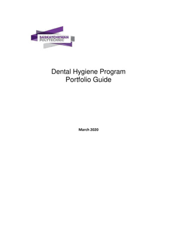
Rensselaer Polytechnic InstituteNetwork and Telecommunications DepartmentDESIGN GUIDELINES1 Symbols Guide :Network SymbolsDrop Location: 2 cat 63Drop Location: 3 cat 64Drop Location: 4 cat 6Pay PhonePWWall PhoneFloor MountedEXExisting Jack110 v 20 amp ReceptacleGRGround BarVertical Sleeve ( Size asIndicated)Horizontal Sleeve ( Size asIndicated)Conduit ( Size as Indicated)Ladder Rack7 foot Equipment Rack ( FrontView) with Cable Managers7 foot Equipment Rack ( TopView) with Cable Managers7
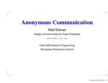
Rensselaer Polytechnic InstituteNetwork and Telecommunications Department125110 TELECOMMUNICATIONS ROOMSTelecommunications Room/Building Equipment RoomsGeneralThe following section will outline the location, design and pathway requirements for BuildingEquipment Rooms (TRB) and Telecommunication Rooms (TR).Figure 1 – Example of a Telecommunications RoomLocationTRBs and TRs locations must meet the following requirements Location should be selected so that the room may be expanded. Shall be located as close as practicable to the center core of the building to minimizehorizontal cable distances (Maximum cable length is 260’ (60m) from TR to drop location) Shall be accessible through common-use corridors that will allow the delivery of large cablereels and equipment and access for repairs 24x7. In multiple floor applications, TRBs and TRs shall have all 4 walls vertically stacked.8
Rensselaer Polytechnic InstituteNetwork and Telecommunications DepartmentTRBs and TRs may not be inside of or be part of a Mechanical space, Equipment room,Washroom, storage area, janitor closet. All room locations must be approved in writing byRensselaer Polytechnic Institute prior to design.Electromagnetic interferenceRooms shall be located away from sources of electromagnetic interference. Special attention shallbe given to electrical power supply transformers, motors and generators, x-ray equipment, elevatorequipment, and induction devices.AccessAccess to the Rooms shall be 24 hours-per-day, 365 days-per-year basis (24x7). Access shall bethrough common use corridors and not accessed by way of any other room.DesignArchitecturalSizeRooms shall have a minimum inside dimension of 8ft. x 10ft. If these rooms require additional squarefootage based on additional requirements, the size shall be determined on a case-by-case basis.Rensselaer Polytechnic Institute must approve all room dimensions in writing.WallsAll four (4) walls shall be floor to deck and have a 2-hour fire rating.Plywood backboardsAll four (4) walls shall be covered with ¾ in. exterior grade plywood, preferably void free. Plywoodshall be fire-rated to meet applicable codes. To reduce warping, fire-rated plywood shall be kiln-driedto maximum moisture content of 15%. Plywood shall be painted on all 6 sides with a white fireretardant paint. Mount plywood 2” above the top of the electrical outlets or surface raceway. Top ofplywood shall be level with the top of the cable tray but shall not exceed 9’ AFF.Ceiling heightThe height between the finished floor and the lowest point of the ceiling should be a minimum of 3 m(10 ft).TreatmentFloors, walls, and ceiling shall be treated to eliminate dust. Finishes shall be light in color to enhanceroom lighting. Floor covering shall be a vinyl anti-static material. Color shall be determined on acase-by-case basis.False ceilingRoom shall not have a false ceiling to permit maximum use of cable pathways both vertically andhorizontally. In such cases where fire-proofing may be sprayed onto the exposed ceiling, the fireproofing shall be treated to mitigate airborne dust.DoorDoors shall be a minimum of 0.9 m (36 in) wide and 2 m (80 in) high, without doorsill, hinged to openoutward (code permitting) or slide side-to-side, or be removable. Consideration should be given to9
Rensselaer Polytechnic InstituteNetwork and Telecommunications Departmentusing double doors with a removable center-post. The door(s) shall be fitted with a lock, which iskeyed for an MH1 key.Floor loadingThe TRBs shall be located on floor areas designed with a minimum floor loading of 4.8 kPa(100 lbf/ft2). The TRs shall be located on floor areas designed with a minimum floor loading of2.4 kPa (50 lbf/ft2). The project structural engineer shall verify that concentrations of proposedequipment do not exceed the floor-loading limit.SignageSignage, if used, should be developed within the security plan of the building.EnvironmentalContaminantsThe rooms shall be protected from contaminants and pollutants that could affect operation andmaterial integrity of the installed equipment.Heating, Ventilation and Air Conditioning (HVAC)Continuous operationHVAC shall be available on a 24 hours-per-day, 365 days-per-year basis. A stand-alone unit shouldbe considered for Telecommunication Rooms.Standby operationIf a standby power source is available in the building, consideration should be given to alsoconnecting the HVAC system serving the Communications Rooms to the standby supply.Operational parametersThe temperature and humidity shall be controlled to provide continuous operating ranges of 18 C(64 F) to 24 C (75 F) with 30% to 55% relative humidity.The ambient temperature and humidity shall be measured at a distance of 1.5 m (5 ft) above the floorlevel, after the equipment is in operation, at any point along an equipment aisle centerline.Positive pressureA positive pressure differential with respect to surrounding areas should be provided with a minimumof one air change per hour.VibrationMechanical vibration coupled to equipment or the cabling infrastructure can lead to service failuresover time. A common example of this type of failure would be loosened connections. If there is apotential for vibration within the building that will be conveyed to the TR via the building structure, theproject structural engineer should design in safeguards against excessive TR vibration.Other mechanical fixturesMechanical fixtures (e.g., piping, ductwork, pneumatic tubing electrical conduits) not related to thesupport of TR/TRB shall not be installed in, pass through, under or enter the TR/TRB. In addition, thearea adjacent to the exterior of the TR/TRB walls shall remain clear for cable pathways entering theTR/TRB.10
Rensselaer Polytechnic InstituteNetwork and Telecommunications DepartmentElectricalLightingLighting shall be a minimum of 500 lx (50 foot candles) measured 1 m (3 ft) above the finished floor,mounted 8.5 ft minimum above the finished floor. Light fixtures must be independently supported fromthe building structure. Light fixtures shall not be mounted to, or supported by the cabletray.NOTE - Lighting fixtures should not be powered from the same electrical distributionpanel as the TR/TRB. Dimmer switches shall not be used and emergency lightingand signs should be properly placed such that an absence of primary lighting will nothamper emergency exit.PowerGeneralEach TR shall contain an electrical sub panel for the TRB and all the TRs that will be fed from thatTRB.TRs shall be fed from the sub panel in the TRB so that all outlets in all TRs are on emergency power.PanelThe electrical sub panel shall be fed from the building emergency electrical power system. The panelshall be sized to accommodate the TRB and all the TRs that will be serviced by it. The panel shallhave a laser printed directory to indicate rooms served by breaker.Equipment 110vOutletsTRBs / TRs shall be equipped with a minimum of two (2) dedicated 110V, 20A circuits. Outlets shallbe 110V, 20A duplex outlets. Outlets may be wall mounted, installed in divided surface raceway orinstalled on Kindorf channel above equipment racks depending on room configuration. Outlets shallbe installed 12" from finished floor to center. All outlets shall have a laser printed circuit identifiersaffixed to it indicating the panel room number, panel ID and circuit number. Rensselaer PolytechnicInstitute Network & Telecommunications Department may specify additional outlets on a case-bycase basis.Convenience 110vOutletsTRBs/ TRs shall be equipped with convenience outlet placed on each wall of the TR for uses otherthan network equipment (i.e. power tools, testing equipment). This outlet shall be run from a separateelectrical panel. All outlets shall have a laser printed circuit identifiers affixed to it indicating the panelroom number, panel ID and circuit number. Network & Telecommunications Department may specifyadditional outlets on a case-by-case basis.Location of power conditioning systemsWhere applicable, dedicated environmental control equipment, such as power conditioning systems,and UPS up to 100 kVA shall be permitted to be installed in the TR. UPS larger than 100 kVA shouldbe located in a separate room. This must be approved in writing by Rensselaer Polytechnic InstituteNetwork & Telecommunications Department prior to design.Bonding and groundingTRBs shall have a TMGB installed to which all TGBs in TRs, equipment, conduits, cable shields,cable trays, sleeves, etc. shall be bonded. The TMGB shall be connected to the main electrical11
Rensselaer Polytechnic InstituteNetwork and Telecommunications Departmentservice ground of the building with a minimum conductor size 2 AWG. A larger conductor size may berequired based on the distance between the TMGB and the main electrical service ground. TheTMGB shall also be bonded to building structural steel.TRs shall have a TGB installed to which all equipment, conduits, cable shields, cable trays, sleeves,etc. shall be bonded. The TGB shall be connected to the TMGB located in the TRB with a minimumconductor size 6 AWG. A larger conductor size may be required based on the distance between theTMGB and the TGB. The conductor shall be continuous from the TMGB to the TGB. The TGB shallalso be bonded to building structural steel if close and accessible. A separately derived ground orisolated ground system is not permitted.Miscellaneous RequirementsFire protectionFire protection of the Telecommunications Rooms, if required, shall be provided as per applicablecode. If sprinklers are required within the spaces, the heads shall be provided with wire cages toprevent accidental operation. Drainage troughs shall be placed under the sprinkler pipes to preventleakage onto the equipment within the room. For some applications, consideration should be givento the installation of alternate fire-suppression systems, confirm applications with RensselaerPolytechnic Institute.Water infiltrationThe TRBs/TRs shall not be located below water level unless preventive measures against waterinfiltration are employed. The room shall be free of water or drain pipes not directly required insupport of the equipment within the room. A floor drain shall be provided within the room if risk ofwater ingress exists.Cable PathwaysGeneralConduits and sleeves should extend 4- 6” into the TR/TRB. If the conduits or sleeves are subject towater intrusion they must drain away from the room and be watertight. All conduits and sleeves musthave the ends plugged upon installation to keep debris from entering the conduits and sleeves. Cabletray shall not be run through walls. Conduits and sleeves must have bushings install at all ends and atall pull boxes. Network & Telecommunications Department must approve all pathway designs inwriting.Conduit pathways built for telecommunication cabling have more stringent bending and pullbox requirements than electrical cabling and must be adhered to (i.e. a telecommunicationsconduit can have no more them 180 degrees of cumulative bends between pull points whereas a conduit installed for electrical wiring may have 360 degrees of bends between pullpoints).Ladder RackAn 18" wide ladder rack shall be run around the inside perimeter of the room for the distribution ofcabling inside the room. An 18” wide ladder rack shall also be run down the center of the room for thefree standing racks that will be installed. The rack shall be mounted 7’0” from finished floor to thebottom of the tray. There shall be no other equipment, lights, conduits, fixtures etc. attached to,mounted on, running through or on the ladder rack except those needed to support the ladder racksystems. Ladder racking may not be run through walls.Sleeves/ConduitsHorizontal UTPThe quantity of horizontal sleeves installed in each TR/TRB for horizontal cabling shall be six (6) 4"sleeves. The sleeves shall be a minimum 8’-0” AFF to the bottom of the sleeves. Sleeves that are12
Rensselaer Polytechnic InstituteNetwork and Telecommunications Departmentinstalled above 9’-0” AFF must have vertical ladder racking installed from the bottom of the sleeve tothe top of the cable tray for lashing of cables in the vertical run.Vertical BackboneIn a multi-store building where TRs are stacked to form a riser, a minimum of three (3) -4” sleevesshall be installed between the stacked TRs.Horizontal Backbone Inter-buildingBackbone pathways in the form of four (4)-4” conduits shall be installed between the TRB of eachbuilding and the nearest designated maintenance hole servicing that building.Horizontal Backbone Intra-buildingIf the TRs are not vertically stacked on the TRB, backbone pathways in the form of Four (4)-4”conduits shall be installed between the TRB of the building and each TR. All conduits and innerductsare to be threaded with a pull rope with footage markers. In multi-story building where TRs arestacked to form a riser, a minimum of four (4)-4” conduits shall be installed between the TRB and thefirst TR in the stack. Cable tray can be used for Inter-building Backbone distribution only with the useof properly sized innerduct or by the installation of a physical separation for the protection of theBackbone cables from general cable installation. Rensselaer Polytechnic Institute must approve useof cable tray as a backbone distribution system in writing.General Telecommunication Room DesignTelecommunication Room design shall follow all BICSI TDMM design recommendations. RensselaerPolytechnic Institute must approve all final design in writing. A detailed T3 drawing will be required forTelecommunication Plans, for more information on drawing detail see BICSI TDMM 9th Edition.25120 EQUIPMENT ROOMS AND SERVICE ENTRANCESGeneralEquipment Rooms / PBX and Service Entrance Rooms shall be located and designed on a case-bycase basis with Rensselaer Polytechnic Institute.25130 INTERIOR COMMUNICATIONS PATHWAYSGeneralThe Interior Communications Pathways will provide a distribution system for all system cabling thatwill be served by the building TRs. The pathways for a building may include all or some of thefollowing, cable tray, continues conduit systems, conduit stubs, sleeves, and cable hangers. Allpathways must be approved in writing by Rensselaer Polytechnic Institute prior to design completion.Interior pathway design shall follow all BICSI TDMM design recommendations and TIA568-B andTIA569-A standards. A detailed T1 and Pathway Logical drawing will be required for all PathwayPlans, for more information on drawing detail see BICSI TDMM 9th Edition.Conduit pathways built for telecommunication cabling have more stringent bending and pullbox requirements then electrical cabling and must be adhered to (i.e. a telecommunicationsconduit can have no more them 180 degrees of cumulative bends between pull points whereas a conduit installed for electrical wiring may have 360 degrees of bends between pullpoints).13
Rensselaer Polytechnic InstituteNetwork and Telecommunications DepartmentInterior PathwaysCable TrayA continuous cable tray system shall be installed on each floor. Minimum tray size shall be 24" x 4"deep with 1" rungs every 9" on floors that have a TR . For all other floors the cable tray shall be 18" x4" deep with 1" rungs every 9". When making turn and elevation changes the appropriate trayaccessories, having the proper bend radius, must be used. For access to, and installation of, cablesin the cable tray, the following clearances are required around the cable tray. The cable tray systemshall have 1’-0” clearance measured from the top most surface of the tray. Access from the sidesshall be 6" to 1’. Access to the cable tray from below shall be unobstructed its entire length; MUSTHAVE A DROP OUT RADIUS BEND- APPROVED BY NETWORK & TELECOMMUNICATIONSDEPARTMENT. There shall be no other equipment, lights, conduits, fixtures etc. attached to,mounted on, running through or on the cable trays except those needed to support the tray systems.Cable tray may not be run through walls. The tray shall stop at all walls where sleeves or conduits willbe installed, the tray shall continue on the others side of the wall.Conduit:GeneralSizes indicated for conduits are trade sizes in all cases.Conduits shall have an insulated bushing installed prior to the installation of telecommunicationscabling.Conduits must have the ends plugged upon installation to keep debris from entering them.Conduit needs to run in the most direct route possible, usually parallel with building lines.Conduit runs shall contain no continuous sections longer than 100 feet. If runs total more than 100feet, pull points or pull boxes need to be inserted.Conduit shall have no more than 180 degrees of cumulative bends between pull points or more than90 degrees of bends at any one point.Electrical Metallic Tubing shall be electro-galvanized steel.(See specifications section 25130 for conduit detail)Intra-building Backbone Conduits:See TR pathway requirements in section 25110Outlet / Conduit locationNew construction wall outletConduit from the cable tray to a typical wall outlet should be a minimum of 1”. Each 1” conduit willservice only one wall outlet location. The conduit will be terminated in a 4” x 4” x 2.75” deep box witha pull string. The box shall be fitted with either a single or double gang mud ring to suit the outletconfiguration required. (See 25160 for outlet types)Outlets are typically located at the following heights to center: Desks18” AFF Wall Phones48” AFF Pay Phones48” AFFConduits run to the cable tray should end approximately 4”- 6” inches away from the top or bottomedge of the cable tray to maintain a proper bend radius.14
Rensselaer Polytechnic InstituteNetwork and Telecommunications DepartmentNew construction floor outletConduit from the cable tray to a typical floor outlet should be a minimum of 1”. Each 1” conduit willservice only one floor outlet location. The conduit will start at the cable tray located on the same flooras the work area. Confirm all floor outlets meet Fire Code and will accommodate manufacturers jacksand outlets.RenovationsFor areas being renovated, the minimum requirement is for horizontal wiring to be properly supportedand secured in the work area in either surface raceway, communications pole, enclosed within thewall or furniture and not exposed to possible damage. From the cable tray to the outlet location, in thearea above the drop ceiling, the cable shall be supported by CAT 6 approved cable hangers mounteda minimum of 6” above the ceiling at a maximum distance of 3”on center.SleevesSizes indicated for sleeves are trade sizes in all cases.Sleeves shall have an insulated bushing installed prior to the installation of telecommunicationscabling.Sleeves must have the ends plugged upon installation to keep debris from entering them.Sleeves used at wall transition points for cable tray systems shall be 4”. Quantity of sleeves shall beequal to the capacity of the cable tray.Sleeves for distribution of horizontal cable in renovated areas not having conduits to the cable trayshall be sized so that when all cables have been installed at the completion of the project, the sleevewill be at 40% capacity of the sleeves maximum fill.All sleeves shall have a minimum 2-hour UL listed fire rated assembly installed regardless if the
Washroom, storage area, janitor closet. All room locations must be approved in writing by Rensselaer Polytechnic Institute prior to design. Rooms shall be located away fr be given to electrical power supply transformers, motors and generators, x-ray equipment, elevator equipment, and induction devices. Access t