Transcription
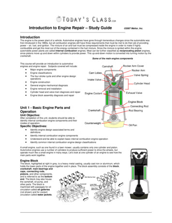
Introduction to Engine Repair – Study Guide 2007 Melior, Inc.IntroductionThe engine is the power plant of a vehicle. Automotive engines have gone through tremendous changes since the automobile wasfirst introduced in the 1880s, but all combustion engines still have three requirements that must be met to do their job of providingpower – air, fuel, and ignition. The mixture of air and fuel must be compressed inside the engine in order to make it highlycombustible and get the most out of the energy contained in the fuel mixture. Since the mixture is ignited within the engine,automobile power plants are called internal combustion engines. Most can be further classified as reciprocating piston engines,since pistons move up and down within cylinders to provide power. This up-and-down motion is converted into turning motion by thecrankshaft.Some of the main engine componentsThis course will provide an introduction to automotiveengines and engine repair. Subjects covered will include: Major engine components Engine classifications The four stroke cycle and other engine designoperations Engine construction General engine mechanical diagnosis Engine removal and installation Cylinder head and valve train diagnosis and repair Engine block assembly diagnosis and repairUnit 1 - Basic Engine Parts andOperationUnit Objective:After completion of this unit, students should be able toidentify internal combustion engine components and theirmodes of operation.Specific Objectives: Identify engine design associated terms and definitionsIdentify internal combustion engine componentsUnderstand and be able to explain basic internal combustion engine operationIdentify common internal combustion engine design classificationsA small engine, such as one found in a lawn mower, usually contains only one cylinder and piston.Automotive engines use a number of cylinders to produce sufficient power to drive the wheels, butoperate much like a small engine in many ways. Let’s look at one cylinder of an engine to see how themain parts work together.Engine BlockThe block, highlighted at right in grey, is a heavy metal casting, usually cast iron or aluminum, whichholds the lower parts of the engine together and in place. The block assembly consists of the block,crankshaft, main bearings andcaps, connecting rods,pistons, and other components,and is referred to as the bottomend. The block may also housethe camshaft, oil pump, andother parts. The block ismachined with passages for oilcirculation called oil galleries(not shown) and for coolantcirculation called water jackets.
2007 Melior, Inc.Introduction to Engine Repair – Study GuideCylindersThe cylinders are round holes or bores machined into the block for the pistons to travel up and down in.PistonsCombustion pressure acts upon the tops of the pistons in the cylinders, forcing them downward. Usually made of aluminum, thepistons transmit the downward force to the connecting rods. The top of the piston’s travel is called Top Dead Center (TDC) and thebottom of a piston’s travel is called Bottom Dead Center (BDC).Piston RingsRings are installed in grooves around the pistons to form a seal between the piston and the cylinder wall. Two types of rings areused: compression rings, which prevent combustion pressure from entering the crankcase, and oil control rings, which preventengine oil from entering the combustion chamber above the piston. Oil rings scrape excess oil from the cylinder walls for return tothe crankcase.CylinderPistonConnecting RodConnecting RodsA rod connects each piston to the crankshaft. The small, upper end of the rod commonly has a bushing pressed into it. A pistonpin, or wrist pin, attaches the piston to the rod through this bushing, which allows the rod to pivot as needed. The larger, lower endof the rod is attached to the crankshaft through rod bearing inserts that are stationary relative to the rod and allow the crankshaft toturn within the rod on a film of oil.CrankshaftThe crankshaft is a strong, alloyed iron or steel shaft that converts the up-and-down motionof the pistons into a turning motion that can be transmitted to the drive train. The crankshaftis supported by the block in several places along its length. The crankshaft rides in mainbearings, which are inserts similar to the rod bearings at these supports. Where thecrankshaft is connected to the rods and where it is supported by the block are calledjournals. The crank is finely machined and polished at these places. The crankshaft is alsodrilled with a network of oil passages to deliver oil under pressure to these places from theoil galleries. Counterweights are formed onto the crankshaft to help prevent vibration.These weights are added to offset the weight of the piston and connecting rod assemblies.At the front of the crankshaft, outside the engine front cover, a heavy wheel containing arubber vibration damper is installed. Also called a harmonic balancer, it often incorporatesthe crank drive belt pulley, which powers belt-driven accessories. At the rear of thecrankshaft, a large flywheel is mounted. The flywheel can serve several purposes: a ringgear is mounted to its circumference to provide a means to start the engine. It also connectsthe engine to the transmission. Finally, on vehicles with manual transmissions, the flywheelis made very heavy to help smooth out power pulses from the engine (this is accomplishedby the torque converter on vehicles equipped with automatic transmissions).Crankshaft-2-
2007 Melior, Inc.Introduction to Engine Repair – Study GuideCylinder HeadLike the engine block, cylinder heads are usually cast from either iron oraluminum. Most V-type, opposed, and W-type engines have two cylinderheads. Inline engines have only one cylinder head. The head bolts to the topof the block, covering and enclosing the tops of the cylinders. The head formssmall pockets over the tops of the pistons called combustion chambers. Thespark plugs are threaded into holes in the head and protrude into thecombustion chambers (gasoline engines). Intake ports and exhaust portsare cast into the head, and small holes called valve guides are machined intoit to position the valves. The valves act as gates. When open, they let air andfuel into the cylinder and exhaust gas out. When closed, they seal thepressure of compression in the combustion chamber. The valves closeagainst machined, press-fitted inserts in the combustion chamber ports calledvalve seats. On overhead cam engines like the one pictured here, the headalso houses the camshaft. The assembly, together with other valve traincomponents and the intake and exhaust manifolds, is referred to as the topend. Between the head and the block, a head gasket seals the combustionchambers, and water and oil passages.Cylinder HeadValve TrainThe valve train consists of the valves, camshaft, and other associated parts.The valves control the flow of the incoming air-fuel mixture and the outgoingexhaust gasses. The intake valves are larger than the exhaust valves, andmany engines today have two intake and two exhaust valves per cylinder toimprove efficiency and performance.Like the crankshaft, the camshaft rides on a film of oil as itrotates on journals. Rotation of the camshaft opens thevalves, and valve springs close them. The camshaft hascarefully machined high spots called lobes that act uponthe valves (or other parts) to open each valve at preciselythe right time. As the lobe moves away, the spring closesthe valve. Some engines have dual overhead cams(DOHC), with a cam for the intake valves and one for theexhaust valves. The engine shown here uses a singleoverhead cam (SOHC).Engines with the camshaft located in the block are calledpushrod engines, because long pushrods are used totransmit the camshaft’s movement up to the rocker arms,which rock to open the valves. On these engines, the camacts on a valve lifter, which in turn acts on a pushrod tomove the rocker arm and open the valve. We will examinethis arrangement later. Overhead cam engines may have aset of parts called valve followers, which operate like lifters.Some engines have a gear on the camshaft to drive theignition distributor and oil pump, and some diesel enginesand older gasoline engines have a rounded lobe on thecamshaft to drive a mechanical fuel pump.The engine top end and bottom end must be timed togetherso that the valves will open and close at the proper timesfor the positions of the pistons, and this is accomplishedthrough the camshaft drive. The camshaft is driven by aTiming Gears and BeltValve Trainsprocket gear mounted on the front of the crankshaft.The sprocket either meshes with a sprocket on the front of the camshaft, or, more often, the two sprockets are linked by a belt or achain. In the engine shown here, timing gears and a timing belt are used. Both sprockets must be installed with their timing marksaligned in the proper positions in order to time the engine.The Four-Stroke Cycle (Otto Cycle)A stroke is one movement of the piston either down from Top Dead Center (TDC) to Bottom Dead Center (BDC), or up from BDC toTDC. The term “stroke” also refers to the physical distance between these two points. One stroke of the piston moves thecrankshaft through one-half of a revolution. Almost all engines on the road today operate on a cycle of four piston strokes. Thestrokes are the intake stroke, compression stroke, power stroke, and the exhaust stroke. This cycle turns the crankshaftthrough two revolutions and then the process begins again.-3-
2007 Melior, Inc.Introduction to Engine Repair – Study GuideIntake StrokeThe process begins with the intake stroke. The piston moves down from top dead center (TDC) to bottom dead center (BDC). Themovement of the piston creates a partial vacuum, drawing air and fuel into the cylinder through the open intake valve. The ideal airfuel mixture for performance, economy and emission control is 14.7 parts air to 1 part fuel. On Throttle Body fuel Injection (TBI)systems and old carbureted systems, fuel is carried in the air stream through an intake manifold and into the intake port. OnMultiport Fuel Injection (MFI) systems, each cylinder has its own injector, which allows fuel to be injected into the port with moreprecision and uniformity than possible with Throttle Body systems. During this stroke, the exhaust valve remains closed.Compression StrokeAfter the piston passes BDC, the compression stroke begins. The intake valve closes and the mixture in the cylinder is compressedby the piston as it moves upward again to TDC. The intake and exhaust valves are both closed during this stroke, so the pressureand temperature of the air-fuel mixture rises. A typical compression ratio for a gasoline engine might be 9:1. The compression ratiois the volume of the cylinder, including the combustion chamber, with the piston at BDC compared to the volume with the piston atTDC. The crankshaft has now made one revolution.Power StrokeThis is what it’s all about! As the piston nears TDC with both valves closed, the compressed air-fuel mixture is ignited. Combustionoccurs, resulting in a tremendous pressure increase that pushes the piston back down the cylinder. This is the power or “working”stroke. The intake and exhaust valves remain closed. In an idling engine, this happens in each cylinder about five times a secondand running at 4,000 RPM it happens over 30 times a second!Exhaust StrokeNow, the spent gasses must be removed from the cylinder to make room for the next air-fuel charge. The exhaust stroke begins asthe piston nears BDC. The exhaust valve opens and the piston moves upward again, pushing the burned exhaust gases out of thecylinder. The intake valve remains closed until the piston has almost reached TDC again. At this point, the engine has completedone full cycle, and the crankshaft has rotated twice. The entire process then repeats.IntakeCompressionPowerExhaustOther Engine DesignsWhile the vast majority of automobile engines are gasoline-powered, four-stroke reciprocating piston engines, other engine designshave been developed and used in automobiles, some quite successfully. Additionally, changing economic, environmental, andpolitical conditions have created a demand to modify or retire this proven workhorse with new or re-worked designs. As materialsand technologies improve and evolve, some of these contenders may come into common use in automobiles.Two-Stroke Cycle EnginesA two-stroke cycle engine is another reciprocating piston design. Every downstroke delivers power in this design, and it has no valvetrain. Instead, in a conventional two-stroke gasoline engine, the air-fuel and exhaust gas are managed by the piston as it covers anduncovers intake and exhaust ports in the side of the cylinder. It also has no oil sump or pressurized oil delivery system, because thecrankcase is part of the fuel delivery system. Instead, the crankcase is lubricated by mixing a small amount of oil with the fuel. Beingable to deliver power with every down stroke and not having a heavy valve train means the two-stroke engine can provide a lot ofpower for its size and weight. Two-stroke engines have been used for many years in small engine applications such as outboardboat engines, motorcycles, ultralight aircraft, chainsaws and lawn equipment, etc. Some two-stroke engine automobiles have beenimported to the U.S., and many medium and heavy duty diesel applications are currently equipped with two-stroke engines.Unfortunately, the light weight and simplicity come at a price. Conventional two-stroke gasoline engines produce higher exhaustemissions and yield lower fuel economy than a comparable four-stroke engine. This is largely due to the burning of the oil in the-4-
2007 Melior, Inc.Introduction to Engine Repair – Study Guidecombustion chamber and leakage of unburned fuel inherent in the engine’s design. The causes of this will be clearer when weexamine the operation of the engine. Neverthele
Introduction to Engine Repair – Study Guide 2007 Melior, Inc. _ Introduction