Transcription
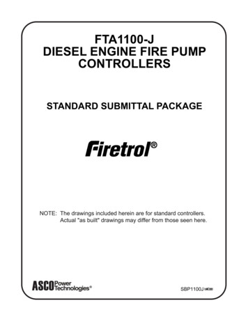
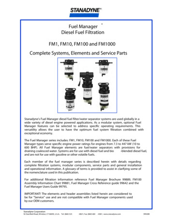
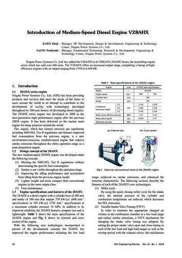
Introduction of Medium-Speed Diesel Engine V28AHXKATO Shoji : Manager, DE Development, Design & Development, Engineering & TechnologyCenter, Niigata Power Systems Co., Ltd.SAITO Toshiyuki : Manager, Fundamental Technology, Research & Development, Engineering &Technology Center, Niigata Power Systems Co., Ltd.Niigata Power Systems Co., Ltd. has added the V28AHX to its NIIGATA 28AHX Series, the bestselling engineseries which has sold over 200 units. The V28AHX offers an increased output range, completing a lineup of highefficiency engines with an output ranging from 2 070 to 6 660 kW.1. Introduction1.1 28AHX series engineNiigata Power Systems Co., Ltd. (NPS) has been providingproducts and services that meet the needs of the times tousers around the world in an attempt to contribute to thedevelopment of society with technologies developedthroughout its 100-year history of developing diesel engines.The 28AHX series engine was developed in 2008 as thenext-generation high performance engine after the previous28HX engine. It has been delivered as the marine mainengine for many purposes around the world.This engine, which has cleared emission gas regulationsincluding IMO-NOx Tier II regulations and features improvedfuel consumption from the previous engine, is a newenvironment-conscious, medium-speed engine that reducessmoke emissions throughout the entire operation range as amain propulsion engine.1.2 Design concept of the 28AHXThe new medium-speed 28AHX engine was developed underthe following concept.(1) Meeting the IMO-NOx Tier II regulations withoutdeteriorating the specific fuel consumption(2) Smoke is not visible throughout the operation range(3) Improving the idling performance and accelerationfrom idling from the previous engine model(4) Lighter weight and more compact than conventionalengines in the same output class(5) Easy maintenance1.3 Engine specifications and features of the 28AHXThe 28AHX is a diesel engine with a cylinder bore of 280 mmand stroke of 390 mm that outputs 370 kW/cyl. (800 min-1specification) or 345 kW/cyl. (750 min-1 specification) ata maximum cylinder pressure 18 MPa. In addition to itsimproved reliability, the 28AHX features compact size and islightweight. Table 1 shows the main specifications of the28AHX engine and Fig. 1 shows its external and crosssection of the engine.With the following new technologies incorporated inpursuit of the development concept, the 28AHX hasimproved the engine performance including the low load10Table 1 Main specifications of the 28AHX engineEngineUnit28AHX main specification̶ModelEngine speedmin-1Cylinder boremmStroke28AHX800750280mmContinuousmaximum output6L8LkW9L3902 2202 0702 9602 7603 3303 105Brake mean effective pressureMPa2.312.30Mean piston speedm/s10.409.75Maximum pressureMPa(a) External view18(b) Cross sectionFig. 1 External and sectional views of the 28AHX enginerange, achieved no smoke emissions, and enhanced thetransient characteristic. The following sections describe thefeatures of each of the 28AHX’s new technologies.(1) Miller cycleBy using the quick closing miller cycle for the intakevalve, the internal pressure of the cylinder andcombustion temperature are reduced, which decreasesthe NOx emissions.(2) Variable Intake Valve Timing (VIVT)In order to maintain the appropriate charged airvolume in the combustion chamber at a low load rangeand reduce smoke emissions, a VIVT mechanism forchanging the intake valve timing was adopted. Bysetting the proper intake valve open and close timing ineach of the low load and high load ranges as well as theoverlap period with the exhaust valves, this mechanismV o l . 51 N o . 1 2 0 18
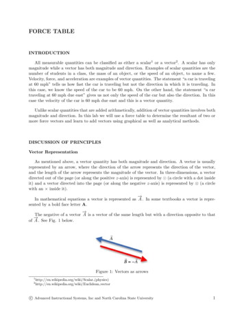
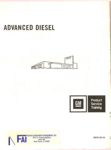
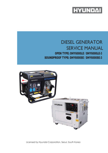
enables a high level of engine performance to bedemonstrated in all load ranges.(3) Improved turbocharging systemBy combining a high-pressure turbocharger with anair bypass and waste gate system, the acceleratingcharacteristics of the engine in the low load range havebeen improved, and this has reduced the amount ofsmoke and enhanced the engine performance in the lowload range. In the high load range, on the other hand,a high boost pressure is maintained, achieving highengine performance throughout the load range.1.4 Operating conditions of the 28AHXWith a shipping record of nearly 200 units as marine mainengines, the 28AHX series is a flagship product of NPS.Figure 2 shows trends in the number of 28AHX enginesdelivered. The operating hours after delivery have exceeded10 000 hours for some of the longer lasting engines. As aresult of our observation of engine performance and maincomponent conditions through much maintenance serviceperformed at the site of the customer, we have confirmed thatthere are no issues. We will continue to monitor the operatingconditions of delivered engines to increase the level ofperfection of the 28AHX.Fig. 3 V28AHX engine(2) Making the engine lighter and smaller thanconventional engines of the same output class2.3 Engine specificationsThe main specifications are the same as the inline engineas follows: a 280 mm cylinder bore, 390 mm stroke,engine output of 370 kW/cyl. (800 min-1 specification) or345 kW/cyl. (750 min-1 specification). Table 2 shows themain specifications of the V28AHX engine.2.4 Engine external viewThe engine was given a slim design by reducing the numberof pipes outside the engine by arranging coolant pipes andother pipes in the V bank between the cylinders. Byarranging main pumps (coolant pumps, lubricant pumps,2. Development of the V28AHX2.1 Development into Vee enginesNPS recently developed the V28AHX (Fig. 3) targeting notonly marine main engines, but also main generator enginesfor electric propulsion and other generator engines for landuse, with the aim of expanding the output range of the28AHX series. By using a 3D-CAD system for enginedesign to fully utilize 3D models for performance simulation,structural and fluid analysis, etc., NPS optimized the partshapes and reduced part weights which were required toachieve the performance goal.2.2 Development concept of the V28AHXBefore developing the V28AHX, NPS emphasized thefollowing points in its design.(1) Maintaining and improving the performance of theinline 28AHX engine and increasing its outputTable 2 Main specifications of the V28AHX engineEnginemin-1Cylinder boremmStrokeMaximum pressureMPa20500Total number of engines delivered (unit)Number of engines delivered per year (unit)9.7518(b) Purpose of use as marine engines25020152.3010.4010020146 210m/s4020135 5206 660Mean piston speed150201218 V4 1405 9202.31602011kW4 440MPa200201039012 V16 V750280Brake mean effective pressure800V28AHX800mmContinuousmaximum output: 9-cylinder: 8-cylinder: 6-cylinder: Total number of engines deliveredV28AHX main specification—Engine speed(a) Trends in the number of engines delivered100UnitModel: Z-PELLER ship: Other29%71%Year (y)Fig. 2 Trends in the number of 28AHX engines deliveredV o l . 51 N o . 1 2 0 1811
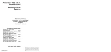
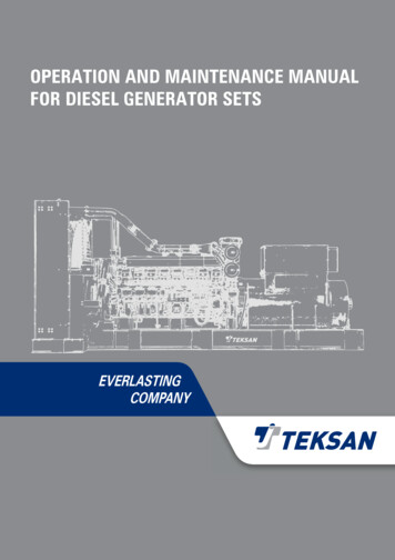
(a) External view(b) Cross sectionof the wooden pattern for casting the V28AHX engine andthe measurement results. The charge air cooler case containingthe charge air cooler also serves as the turbocharger base andit is linked to the cylinder block via the joint block. The jointblock also functions as the interface for the coolant, lubricant,and charge air from turbocharger, contributing to the reductionof pipes surrounding the turbocharger base, simplification ofthe structure, and ease of assembly work.2.5.2 CrankshaftFor the crankshaft, lightweight and a good balance ratio areachieved by machining the entire crank arms to reducevariations in the weight between crank throws and also withthe balance weight attached to each crank throw. In addition,while ensuring the required torsional and bending rigidity inthe crank arm shape with the automatic shape optimizationtechnology using the FEM, the crank arm weight wasreduced by approximately 15% from conventional engines.As a result of these weight reduction efforts, the V28AHXis approximately 15% lighter and approximately 10% smallerthan NPS’s medium-speed diesel engines with a 280 mmcylinder bore and the same output range. Figure 6 shows acomparison of weights and dimensions.2.6 Example application of simulation technologyIn order to improve the engine performance and reduce theengine weight at the same time, simulation technology isactively used for the development of new engine types. As1.10: Conventional engine: V28AHX engine1.05Dimensionless number (–)etc.) on the free end side of the engine, the interface with theship and the plant is simplified. In addition, for improvedmaintenance, a turning gear is provided as standard. Theexhaust system supports both the pulse turbocharging systemand the single pipe turbocharging system. Figure 4 showsthe external and sectional views of the V28AHX engine.2.5 Optimization of engine components and reducingengine weightMain parts that have many established results in inlineengines were used in common with the V28AHX, whichensured the engine performance and the reliability andshortened the design period. As for unique parts for Veeengines, such as the cylinder block and crankshaft, strengthand fluid flow were examined by using 3D-CAD andsimulation techniques to optimize the parts shape, reduce theparts weight, and improve the engine performance. Thefollowing section explains these parts in detail.2.5.1 Cylinder blockFor the cylinder block, NPS’s high strength ductile cast ironwas used and the high rigidity hanger type was adopted. Thecylinder block was designed through structural analysis usingthe Finite Element Method (FEM) to optimize the structureand make it lightweight. Since the cylinder block is made ofa large size of cast iron, when creating a wooden pattern forcasting, the 3D measurement of the wooden pattern wasconducted to check for differences with the shape in thedrawing in places such as wall thickness. As a result, theproduct accuracy improved and the engine is 30% lighter thanconventional engines. Figure 5 shows the 3D measurement1.000.950.900.850.800.75Fig. 4 External and sectional views of the V28AHX engine(a) Measurement situationEngine lengthEngine widthEngine heightMassFig. 6 Comparison of weight and dimensions between the V28AHXand NIIGATA’s conventional engines(b) Measurement resultsDifference between thewooden pattern for castingand shapes in the drawing(mm)1086420 2 4 6 8Fig. 5 3D measurement situation and measurement results of a wooden casting mold for the V28AHX engine12V o l . 51 N o . 1 2 0 18
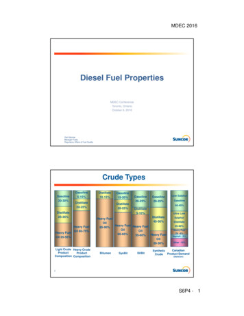
explained in Section 2.5, unique parts for Vee engines weredeveloped and main parts that have many established resultsin inline engines were used in common with the V28AHX.When using the parts in common with inline engines in a Veeengine, connections with adjacent main parts may change.Here, NPS also used simulation technology to examine theissue.As application case studies, the following are introduced inthis article: ① Shape optimization of the charge air coolercase, which was developed as a unique part for Vee engines,② Shape optimization of the intake manifold connecting thecylinder head intake port and the cylinder block, and ③ Shapeoptimization of the coolant connecting pipe connecting thecylinder head coolant inlet and the main coolant pipe.2.6.1 Case study on shape optimization of the chargeair cooler caseIn general, a diesel engine charges the cylinder with highpressure air by using a turbocharger to increase output andefficiency. However, since the temperature of the compressedair is high but its density is low, there is a limitation toimprove charging efficiency without any measures. For thisreason, a charge air cooler is installed between the turbochargerand the engine so that charge air from the turbocharger canbe cooled to increase the charging efficiency. The charge airsupplied from the turbocharger is led to the charge air coolercase containing the charge air cooler. After being cooled, thecharge air is supplied to the charge air supply surge tank builtinto the cylinder block. A baffle plate is provided in the inletduct of the charge air cooler case, which guides a balancedflow of charge air to the charge air cooler. In the developmentof the V28AHX, Computational Fluid Dynamics (CFD) wasused to optimize the shape of the inlet duct and baffle plate inthe charge air cooler case, improving the charge air flowinside the charge air cooler case. Figure 7 shows the velocitydistribution in the upstream cross-section of the V28AHXcharge air cooler. It shows that there are high and lowvelocity areas, causing a very uneven flow in the initial shape(Fig. 7-(a)). On the other hand, in the final shape (Fig. 7-(b)),NPS successfully positioned the baffle plate and added aprojection to it to obtain more uniform velocity distribution.These improvements improved the heat exchange efficiency,resulting in the smaller charge air cooler and charge aircooler case that contributed to the compact size and lighterweight as well as the higher performance of the engine.2.6.2 Case study on shape optimization of the intakemanifoldAs explained in the previous section, the charge air suppliedfrom the turbocharger is cooled by the charge air cooler andled to the charge air supply surge tank built into the cylinderblock. From the charge air supply surge tank, the charge airpasses through the intake manifold and the cylinder headintake port for each cylinder and is then supplied to thecombustion chamber. In order to improve the engineperformance, the flow coefficient of the intake manifold andcylinder head intake port needed to be increased. For thisreason, the shapes of these parts were optimized whendeveloping the inline engine. Although the cylinder head ofthe V28AHX is a part used in common with the inlineengines, due to a change in the engine layout, the intakemanifold was designed from scratch. Therefore, NPS usedCFD to optimize the shape of the intake manifold and arrivedat a shape that achieves the same or better flow coefficientthan the inline engine.Figu
of the wooden pattern for casting the V28AHX engine and the measurement results. The charge air cooler case containing the charge air cooler also serves as the turbocharger base and it is linked to the cylinder block via the joint block. The joint block also functions as the interface for the coolant, lubricant, and charge air from turbocharger, contributing to the reduction of pipes .