Transcription
AN 822: Intel FPGA ConfigurationDevice Migration GuidelineSubscribeSend FeedbackAN-822 2020.04.29Latest document on the web: PDF HTML
ContentsContents1. Intel FPGA Configuration Device Migration Guideline.31.1. Migration Considerations.31.2. Software Migration Guidelines. 51.2.1. IP Core Compatibility. 51.2.2. Programming File Compatibility. 61.2.3. IP Core and Programming File Migration Guideline.71.2.4. Software Support for EPCQ-A Devices. 101.3. Specification Comparison. 101.3.1. Operating Conditions. 111.3.2. Timing Specifications.111.3.3. Operation Codes. 141.3.4. Pin Information.161.3.5. Package Dimensions.181.3.6. Status Register. 211.4. Evaluating Data Setup and Hold Timing Slack. 241.5. Migration Method from EPCQ to EPCQ-A for Arria V, Cyclone V, and Stratix V Devices. 261.5.1. Board Design Guidelines for the Active Serial (AS) Configuration Scheme. 261.6. Cyclone V to Cyclone V QS Device Migration Reference Manual.411.7. Document Revision History for AN 822: Intel FPGA Configuration Device MigrationGuideline. 45AN 822: Intel FPGA Configuration Device Migration Guideline2Send Feedback
AN-822 2020.04.29Send Feedback1. Intel FPGA Configuration Device Migration GuidelineThis document describes the guidelines for migrating from the Serial Configuration(EPCS) and Quad-Serial Configuration (EPCQ) devices to the Quad-Serial Configuration(EPCQ-A) devices.Related Information Serial Configuration (EPCS) Devices Datasheet Quad-Serial Configuration (EPCQ) Devices Datasheet Quad-Serial Configuration (EPCQ-A) Devices Datasheet1.1. Migration ConsiderationsThe EPCQ-A devices are conditionally compatible for a direct migration from EPCQ andEPCS devices.You must consider the following items to determine the compatibility and the nextstep of action for a successful device migration.IP CoresIf you are using Intel IP cores, you may need to regenerate and recompile yourdesign. In certain conditions, the programming files can be reused withoutrecompilation. Refer to IP Core Compatibility on page 5 for more information aboutIP core compatibility. Refer to Table 3 on page 6 if you are not using IP cores thatinterface with the configuration device.Pins, Package and CapacityMigration can only be done to an EPCQ-A device that has sufficient capacity for theprogramming file and have the same pin count package.Pin 3 (nRESET) on the EPCQ64A and EPCQ128A devices act as a reset pin. This pinhas an internal pull-up, and if you do not use the reset function, connect the nRESETpin to either VCC or leave it unconnected. Refer to Pin Information on page 16 formore information about the pin-outs and descriptions.Intel Corporation. All rights reserved. Agilex, Altera, Arria, Cyclone, Enpirion, Intel, the Intel logo, MAX, Nios,Quartus and Stratix words and logos are trademarks of Intel Corporation or its subsidiaries in the U.S. and/orother countries. Intel warrants performance of its FPGA and semiconductor products to current specifications inaccordance with Intel's standard warranty, but reserves the right to make changes to any products and servicesat any time without notice. Intel assumes no responsibility or liability arising out of the application or use of anyinformation, product, or service described herein except as expressly agreed to in writing by Intel. Intelcustomers are advised to obtain the latest version of device specifications before relying on any publishedinformation and before placing orders for products or services.*Other names and brands may be claimed as the property of others.ISO9001:2015Registered
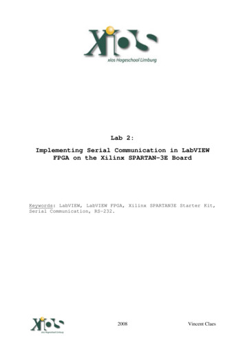
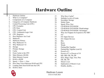
1. Intel FPGA Configuration Device Migration GuidelineAN-822 2020.04.29Figure 1.EPCS to EPCQ Migration Pin Package and Capacity SummaryTo EPCQ-AVariantFromEPCSFromEPCQEPCQ4A1 EPCQ16A EPCQ32A EPCQ64A Yes 2YesYesNoNoEPCS64NoNoNoYesYesEPCS128NoNoNoYes 2YesEPCQ16NoYesYesNoNoEPCQ32NoYes 2YesNoNoEPCQ64NoNoNoYesYesEPCQ128NoNoNoYes 2YesNote:1. EPCQ4A devices support Active Serial x1 configuration only.2. Migration is compatible only if the destination EPCQ-A device hasthe sufficient capacity for the programming file.Operation CommandsThe dummy clock requirement of the fast read (0Bh) and extended quad input fastread (EBh) commands: EPCQ—the dummy clock is configurable with the non-volatile configuration register(NVCR). When the EPCQ is used with a Cyclone V, Arria V or Stratix V device,the dummy clock is configured to be 4, 10 or 12, depending on the byteaddressing mode and ASx1 or ASx4 configuration. However, in EPCQ-A devices,the dummy clock is fixed at 8 and 6 for fast read and extended quad input fastread respectively. Therefore you must regenerate the programming files, suchas .pof, .jic, and .rpd. EPCS—the dummy clock is fixed at 8 for fast read, therefore you do not have toregenerate the programming files if all other conditions are met. Table 3 on page6 defines the need to regenerate the programming files. Refer to IP Core andProgramming File Migration Guideline on page 7 for more information about theconditions.Status RegisterStatus Register contains the Top/Bottom (TB) bit (bit 5), Block Protect (BP) bits (bit 4,bit 3, bit 2) for sector protection bits. EPCS devices do not have TP bit and some EPCQdevice densities have BP3 (bit 6), while bit 6 is reserved in EPCQ-A devices. Due tothis differences, you may need to recompile the programming file if your design usesthe sector protect feature. Refer to Status Register on page 21 for more informationabout status registers and sector protect bits.AN 822: Intel FPGA Configuration Device Migration Guideline4Send Feedback
1. Intel FPGA Configuration Device Migration GuidelineAN-822 2020.04.29Sector SizeAll of the EPCS, EPCQ and EPCQ-A devices have the sector size of 512kb except forEPCS128 which has 2Mb. This impacts the sector erase operation. If the design iserasing the flash during user mode, you must update your design to comply the sectorsize when migrating from EPCS128 to EPCQ128A. After updating your design,regenerate a new programming file for the EPCQ-A device.1.2. Software Migration GuidelinesWhen you use a legacy device that is not supported in the Intel Quartus Primesoftware version 17.1 and later and you need to modify your design to migrate theconfiguration device to EPCQ-A, you need to use 13.1.4 patch 4.70r. For moreinformation, refer to the readme patch instructions and the patches for Windows andLinux in the Software Download page of the FPGA Configuration Devices Supportwebsite.Related InformationFPGA Configuration Devices Support Software Download1.2.1. IP Core CompatibilityTable 1.EPCS to EPCQ-A Device Migration IP Core CompatibilityIP CoreCompatibilityConditionASMI ParallelYes/No Serial Flash ControllerYes/No Serial Flash Loader (SFL)Yes/No Remote UpdateTable 2.If sector protect is used, refer to Sector Protect on page 21 todetermine compatibility.EPCS128 has different sector size than EPCQ128A, notcompatible if sector erase is used.Compatible for Cyclone V, Arria V and Stratix V devices.For devices earlier than Cyclone V, Arria V and Stratix V, it iscompatible if the Enhanced SFL(1) is enabled.YesEPCQ to EPCQ-A Device Migration IP Core CompatibilityIP CoreASMI ParallelCompatibilityYes/NoCondition ASMI Parallel IINo—Serial Flash ControllerNo—Serial Flash Controller IINo—Generic QSPI ControllerNo—If sector protect is used, refer to sector protect tablecomparison to determine compatibility.Not compatible if read dummy clock is enabled.continued.(1)Enhanced SFL is an option available in the Serial Flash Loader IP core when using with devicesearlier than Cyclone V, Arria V and Stratix V.Send FeedbackAN 822: Intel FPGA Configuration Device Migration Guideline5
1. Intel FPGA Configuration Device Migration GuidelineAN-822 2020.04.29IP CoreCompatibilityGeneric QSPI ControllerIISerial Flash LoaderConditionNo—Yes/No Yes—Remote UpdateCompatible for Cyclone V, Arria V and Stratix V devices.For devices earlier than Cyclone V, Arria V and Stratix V, it iscompatible if the Enhanced SFL(1) is enabled.Related Information Altera Remote Update IP Core User Guide Altera ASMI Parallel IP Core User Guide Converting .sof to .jic Files in the Quartus Prime Software Programming Serial Configuration Devices Using the Quartus Prime Programmerand .jic Files1.2.2. Programming File CompatibilityNote:This section describes programming file compatibility for designs without Intel FPGA IPcores.List of supported programming files: Programmer Object File (.pof) JTAG Indirect Configuration File (.jic) Raw Programming Data (.rpd) STAPL File (.jam/.jbc) Serial Vector Format (.svf)Note:Compression and encryption would not affect the programming file compatibility.Table 3.Programming File Compatibility GuideNote:Device FamilyLegacy FPGAdevicesFor designs that do not contain IP cores which interface with the configuration device,depending upon the FPGA family and configuration scheme implemented, the existingprogramming files may be compatible with EPCQ-A devices without the need to regeneratethe programming Device Density64Mb & belowProgramming Files supportedDisableEPCS/EPCQ IDcheckSettingCompatiblewith s(4)continued.(2)Table assumes other compatibility considerations are satisfied.(3)Table assumes the programming files do not contain any ASMI Parallel IP or Serial FlashLoader IP.AN 822: Intel FPGA Configuration Device Migration Guideline6Send Feedback
1. Intel FPGA Configuration Device Migration GuidelineAN-822 2020.04.29Device ce Density128MbEPCQCyclone V, Arria V,and Stratix VdevicesEPCSAny64Mb & below128MbEPCQ(9)AnyProgramming Files supportedDisableEPCS/EPCQ IDcheckSettingCompatiblewith am/.jbcAnyNo(6)AnyAnyNoRefer to IP Core and Programming File Migration Guideline on page 7 for moreinformation about guidelines on incompatible programming files.1.2.3. IP Core and Programming File Migration GuidelineNote:This section describes programming file compatibility for designs with Intel FPGA IPcores that interface with the configuration device.(2)Table assumes other compatibility considerations are satisfied.(3)Table assumes the programming files do not contain any ASMI Parallel IP or Serial FlashLoader IP.(4)Only supported for .svf files generated for EPCS devices to be used to program an EPCQ-A,and not the other way round.(5)In .rpd file, the binary data is the same between EPCS128 and EPCQ128A. However due todifferent sector size, a proper erasing procedure is required when programming each device.(6)Due to different sector size, the .jam/.jbc file is different between EPCS and EPCQ.(7)In Intel Quartus Prime version 15.1 or later, automatic mode turns on this optionautomatically.(8)Other than Intel Quartus Prime version 13.0 to 15.0, automatic mode turns on this optionautomatically.(9)EPCQ programming files are not compatible with EPCQ-A in AS x1 or AS x4 modes.Send FeedbackAN 822: Intel FPGA Configuration Device Migration Guideline7
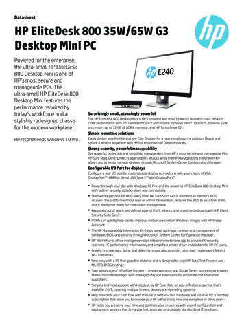
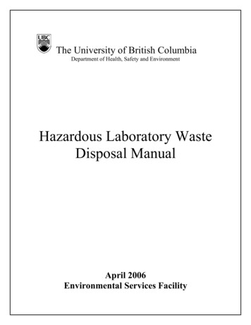
1. Intel FPGA Configuration Device Migration GuidelineAN-822 2020.04.29Refer to the following diagram to determine the subsequent tasks and guidelines formigration: IP core and programming file are incompatible—regenerate IP core andprogramming file shown in IP Core Regeneration Guideline on page 9. Programming file is incompatible—regenerate programming file shown inProgramming File Regeneration Guideline on page 10. IP core and programming file are compatible—no additional task required and youcan reuse the existing programming file.AN 822: Intel FPGA Configuration Device Migration Guideline8Send Feedback
1. Intel FPGA Configuration Device Migration GuidelineAN-822 2020.04.29Figure 2.IP Core and Programming File Compatibility Flow ChartStartIP core iscompatible?1NoYesEPCSEPCQCyclone V, Arria V orStratix V?YesRegenerate IP core andprogramming fileNoYesUse sector protect?Size 32Mb &&SR2[6:5] 2b’00?NoEPCS128 && useerase sector?YesNoNoEPCS64 &&SR2[6] 1b’0?YesNoRegenerate IP core andprogramming fileDisable ID check onprogramming file?NoYesUse .svf file?YesRegenerateprogramming fileNoProgramming fileis compatible3Notes:1. Check IP core compatibility in IP Core Compatibility section.2. SR is status register.3. IP core and programming file can be migrated without regeneration.1.2.3.1. IP Core Regeneration GuidelineTo regenerate the IP core and programming file with the correct settings, perform thefollowing steps:1. Regenerate the desired IP cores.a.Send FeedbackIf you use the sector protect feature:AN 822: Intel FPGA Configuration Device Migration Guideline9
1. Intel FPGA Configuration Device Migration GuidelineAN-822 2020.04.29b. For EPCQ4A, EPCQ16A, and EPCQ32A—ensure the status register bit [6:5]is set to 0. For EPCQ64A—ensure the status register bit [6] is set to 0.For EPCS128 to EPCQ128A migration—sector erase must comply to the sectorsize of EPCQ128A.Note: Sector size for EPCS128 and EPCQ128A are 2Mb and 512kb respectively.2. Recompile the configuration bitstream to obtain the .sof file.1.2.3.2. Programming File Regeneration GuidelineTo regenerate the programming file with the correct settings, perform the followingsteps:1.2.Convert the .sof file to the desired programming file in the Intel Quartus PrimeConvert Programing File tool and ensure that you: Select the correct EPCQ-A device you are migrating to. Enable the Disable EPCS/EPCQ ID check option. This option is available inthe Advanced Option settings of the Convert Programming File tool in IntelQuartus Prime software. For migration from EPCS devices—Select AS x1 configuration mode.Program the programming file into EPCQ-A device using Intel Quartus PrimeProgrammer.1.2.4. Software Support for EPCQ-A DevicesTable 4.Intel Quartus Prime Software Support for EPCQ-A DevicesFor more information about using the EPCQ-A device with the ASMI Parallel II Intel FPGA IP Core in the IntelQuartus Prime Standard Edition software before version 17.1, refer to the How can I use EPCQ-A SerialConfiguration Devices in ASMI Parallel II Intel FPGA IP when using Intel Quartus Prime Standard Editionsoftware version 17.0.2 and earlier?IP CoresProgrammer and Programming FileGenerationIntel Quartus Prime Pro Edition 17.1NoYesIntel Quartus Prime Standard Edition17.1YesYesIntel Quartus PrimeRelated InformationHow can I use EPCQ-A Serial Configuration Devices in ASMI Parallel II Intel FPGA IPwhen using Intel Quartus Prime Standard Edition software version 17.0.2 andearlier?1.3. Specification ComparisonThe following tables show the side-by-side comparison of the EPCS, EPCQ and EPCQ-Aoperating conditions. For more detailed and up-to-date information, refer to therespective device datasheet.AN 822: Intel FPGA Configuration Device Migration Guideline10Send Feedback
1. Intel FPGA Configuration Device Migration GuidelineAN-822 2020.04.291.3.1. Operating ConditionsTable 5.EPCS, EPCQ and EPCQ-A Devices Operating CQ-AEPCSEPCQUnitEPCQ-ASupplyvoltageThe maximumVCC rise time is100 ms.VCC2.73.6VOperatingtemperatureFor industrialuseTA-4085 CHigh-levelinput voltage—VIHVCC 0.4VLow-levelinput voltage—VIL-0.50.3 x VCCVHigh-leveloutputvoltageIOH -100µAVOHVCC - 0.2—VLow-leveloutputvoltageIOL 100µAVOL—0.2 or 0.4(12)V0.7 x VCC(10)(11)1.3.2. Timing SpecificationsThe following tables show the general comparison of the EPCS, EPCQ, and EPCQ-Aoperation timing. For more detailed and up-to-date information, refer to the respectivedevice datasheet.Caution:You need to take note of these values to avoid from the migration to fail: tDH tDSU tnCLK2D/tCLQV tCLQX(13)(10)The FPGA 2.5V I/O VOH level is insufficient to achieve EPCQ or EPCQ-A VIH threshold acrossentire voltage range.(11)The minimum VOH for 3V or 3.3V LVTTL is 2.4V in the Intel FPGA device. This specification isbased on the worst condition. Since the input current of EPCQ and EPCQ-A is small enough,the VOH of Intel FPGA device does not violate the minimum VIH of EPCQ and EPCQ-A in theusual usage. Intel recommends that you perform simulation using the IBIS model to ensurethe required specifications are achieved.(12)0.2 V for EPCQ16A, EPCQ32A, EPCQ64A, and EPCQ128A. 0.4 V is for EPCQ4A(13)Refer to Evaluating Data Setup and Hold Timing Slack on page 24 evaluate the data setupand hold timing slack.Send FeedbackAN 822: Intel FPGA Configuration Device Migration Guideline11
1. Intel FPGA Configuration Device Migration GuidelineAN-822 2020.04.291.3.2.1. Read Operation TimingTable 6.EPCS and EPCQ-A Devices Read Operation Timing ParametersSymbolftttRCLKParameterODISTable 7.UnitEPCSEPCQ-AEPCSEPCQ-A——2050MHzFast read clock frequencyAll——40100MHz——nsOutput disable time after readClock falling edge to DATA4 or6(14)4 Mb11All others113.4 or9(15)——4Mb114 or 6(14)——All others113.4 or9(15)——All——87ns4Mb——88nsAll others——86nsEPCQ and EPCQ-A Devices Read Operation Timing ParametersSymbolRCLKMaxAllDCLK low timeCLMinRead clock frequencyDCLK high timeCHt nCLK2D EPCQ-AEPCQEPCQ-ARead clock frequencyAll——5050MHzFast read clock frequencyAll——100100MHztCHDCLK high timeAll43.4 or9(15)——nstCLDCLK low timeAll43.4 or9(15)——nstODISOutput disable time after readAll——87nsClock falling edge to DATAAll——76nst nCLK2D /tCLQV(16)1.3.2.2. Write Operation TimingTable 8.SymbolEPCS and EPCQ-A Devices Write Operation Timing ParametersOperationCapacityMinEPCSfWCLKWrite clock frequencyAlltCHDCLK CQ-A25100——MHznscontinued.(14)4 ns is for normal read and 6 ns is for fast read.(15)3.4 ns is for normal read and 9 ns is for fast read.(16)tnCLK2Dis used in EPCS and EPCQ devices while tCLQV is used in EPCQ-A devices.AN 822: Intel FPGA Configuration Device Migration Guideline12Send Feedback
1. Intel FPGA Configuration Device Migration GuidelineAN-822 2020.04.29SymboltCLOperationDCLK l others203.4——4204——All others204——UnitEPCQ-AnstNCSSUChip select ( nCS ) setupAll105——nstNCSHChip select ( nCS ) holdAll105——nstDSUDATA[] in setup beforeDCLK rising edgeAll52——nstDHDATA[] hold time afterDCLK rising edge455——nsAll others53——4100100——All others10010 /50(17)——ttCSHWBChip select ( nCS ) highWrite bytes mstWSWrite status cycleAll—5101515mstEBErase bulk 31sAll others—20.1532stESTable 9.Erase sector cycleEPCQ and EPCQ-A Devices Write Operation Timing te clock frequencyAlltCHDCLK highAll43.4——tCLDCLK lowAll44——MHznsnscontinued.(17)10ns for read and 50 ns for erase program and write.Send FeedbackAN 822: Intel FPGA Configuration Device Migration Guideline13
1. Intel FPGA Configuration Device Migration GuidelineAN-822 Q-AEPCQMaxEPCQ-AEPCQUnitEPCQ-AtNCSSUChip select ( nCS ) setupAll45——nstNCSHChip select ( nCS ) holdAll45——nstDSUDATA[] in setup beforeDCLK rising edgeAll22——nstDHDATA[] hold time afterDCLK rising edgeAll33——nstCSHChip select ( nCS ) highAll5010 /50(18)——nstWBWrite bytes 128—0.60.753mstWSWrite status cycleAll—1.310815mstEBErase bulk 8—17040250200sAll others—0.70.1532s128—0.70.1562stESErase sector cycle1.3.3. Operation CodesThe following tables summarize EPCS, EPCQ, and EPCQ-A operation codes. For moredetailed and up-to-date information, refer to the respective device datasheet.Table 10.EPCS, EPCQ and EPCQ-A Devices Operation Codes SummaryOperationOperation CodeEPCSEPCQWrite status01hWrite bytes02hRead bytes03hWrite disable04hRead status05hWrite enable06hFast read0BhRead silicon IDABh(19)—EPCQ-AABhcontinued.(18)10ns for read and 50 ns for erase program and write.AN 822: Intel FPGA Configuration Device Migration Guideline14Send Feedback
1. Intel FPGA Configuration Device Migration GuidelineAN-822 2020.04.29OperationRead device IDOperation CodeEPCSEPCQEPCQ-A9Fh(20)9Fh9FhErase bulkC7hErase sectorD8hErase subsector—20h20hExtended dual input fast read—BBhBBhExtended quad input fast read—EBhEBhExtended dual input fast write bytes—D2h—Extended quad input fast write bytes—12h—Quad input fast write bytes——32h(21)Read NVCR—B5h—Write ��(19)The read silicon ID is available in EPCS1, EPCS4, EPCS16, and EPCS64 devices only.(20)The read device ID is available in EPCS128 devices only.(21)Quad input fast write bytes operation is not supported in Intel IP cores.Send FeedbackAN 822: Intel FPGA Configuration Device Migration Guideline15
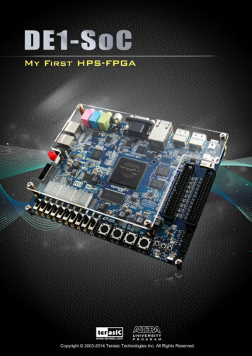
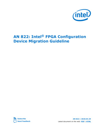
1. Intel FPGA Configuration Device Migration GuidelineAN-822 2020.04.291.3.4. Pin Information1.3.4.1. 8-pin SOIC Device Pin InformationFigure 3.Pin-Out Diagram for 8-pin SOIC EPCS, EPCQ and EPCQ-A DevicesAS x1nCSDATAVCCGNDEPCS1234EPCQ/EPCQ-A8765AS DATA0Leave all N.C pins unconnected.Table 11.Pin Comparison for 8-pin SOIC EPCS, EPCQ and EPCQ-A DevicesPin NumberAS AN 822: Intel FPGA Configuration Device Migration Guideline16AS x4EPCQSend Feedback
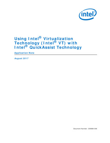
1. Intel FPGA Configuration Device Migration GuidelineAN-822 2020.04.291.3.4.2. 16-pin SOIC Device Pin InformationFigure 4.Pin-Out Diagram for 16-pin SOIC EPCS, EPCQ and EPCQ-A DevicesAS .C.N.CN.CN.CGNDVCCEPCQAS TA2Notes: Leave all N.C pins unconnected.There is an internal pull-up resistor for the dedicated nRESET pin. If the reset function is not needed, connect this pin to Vcc or leave it unconnected.Table 12.Pin Comparison for 16-pin SOIC EPCS, EPCQ and EPCQ-A DevicesPin NumberAS x1EPCSAS ot connectednRESET(22)Not connected4, 5, 6, 11, 12, 13and 14Not connectedNot 2)DATAASDIDATA0DCLKDATA0DCLKThere is an internal pull-up resistor for the dedicated nRESET pin. If the reset function is notneeded, connect this pin to Vcc or leave it unconnected.Send FeedbackAN 822: Intel FPGA Configuration Device Migration Guideline17
1. Intel FPGA Configuration Device Migration GuidelineAN-822 2020.04.291.3.5. Package Dimensions1.3.5.1. 8-Pin SOIC Device Package DimensionsFigure 5.Package Dimension Diagram for 8-Pin SOIC Package DevicesTable 13.Package Dimension Comparison for 8-Pin SOIC Package DevicesSymbolMin (mm)Typical (mm)Max ��——1.65—D——4.90 BSC4.90 BSC——E——6.0 BSC6.0 BSC——E1——3.90 BSC3.90 BSC—A—continued.AN 822: Intel FPGA Configuration Device Migration Guideline18Send Feedback
1. Intel FPGA Configuration Device Migration GuidelineAN-822 2020.04.29SymbolMin (mm)Typical (mm)Max .40.4——1.271.27L1——1.04 0.250.25e——1.27 BSC1.27 BSC——Theta0 0 ——8 10 LSend FeedbackAN 822: Intel FPGA Configuration Device Migration Guideline19
1. Intel FPGA Configuration Device Migration GuidelineAN-822 2020.04.291.3.5.2. 16-Pin SOIC Device Package DimensionsFigure 6.Package Dimension Diagram for 16-Pin SOIC Package DevicesTable 14.Package Dimension Comparison for 16-Pin SOIC Package DevicesSymbolMin (mm)Typical (mm)Max 5——2.552.55D—10.0810.3 BSC——10.49E—10.0110.3 BSC——10.64E1—7.397.50 BSC——7.590.40.38——1.271.27L1——1.40 Ref1.40 Ref——b0.310.31——0.51AL0.51continued.AN 822: Intel FPGA Configuration Device Migration Guideline20Send Feedback
1. Intel FPGA Configuration Device Migration GuidelineAN-822 2020.04.29SymbolMin (mm)Typical (mm)Max 0.20.20——0.330.33e——1.27 BSC1.27 BSC——Theta0 0 ——8 8 1.3.6. Status RegisterTable 15.BitStatus Register Bits for EPCS, EPCQ and EPCQ-A 4/16/64/128EPCQ-A16/3264/128AllReservedBlock Protect Bit 3R/WNoNoNoYesNoTop/Bottom BitR/WNoNoYesYesYesBP2Block Protect Bit 2R/WNoYesYesYesYes3BP1Block Protect Bit 1R/WYesYesYesYesYes2BP0Block Protect Bit 0R/WYesYesYesYesYes1WELWrite Enable LatchRYesYesYesYesYes0WIPWrite In ProgressRYesYesYesYesYes1.3.6.1. Sector ProtectTable 16.Sector Protect Comparison for EPCS4 and EPCQ4A DevicesNote:Set TB bit to 0 for backward compatibility.Status Register(23)EPCS4EPCQ4ATBBP2BP1BP0Protected Sectors (8 N/A01010N/A0-11011N/A0-3x1xxAllAllThis is a reserved bit in EPCQ-A device and must be set to 0.Send FeedbackAN 822: Intel FPGA Configuration Device Migration Guideline21
1. Intel FPGA Configuration Device Migration GuidelineAN-822 2020.04.29Table 17.Sector Protect Comparison for EPCS16, EPCQ16 and EPCQ16A DevicesNote:Set TB bit to 0 for backward compatibility for migration from EPCS16.Status AAllAll1111N/AAllAllTable 18.Protected Sectors (32 sectors)Sector Protect Comparison for EPCQ32 and EPCQ32A DevicesStatus RegisterEPCQ32EPCQ32ATBBP2BP1BP0Protected Sectors (64 0-70-7continued.AN 822: Intel FPGA Configuration Device Migration Guideline22Send Feedback
1. Intel FPGA Configuration Device Migration GuidelineAN-822 2020.04.29Status 310-311111AllAllTable 19.Protected Sectors (64 sectors)Sector Protect Comparison for EPCS64, EPCQ64 and EPCQ64A DevicesNote:Set TB bit to 0 for backward compatibility for migration from EPCS64.Status -310-631111N/A0-63AllTable 20.Protected Sectors (128 sectors)Sector Protect Comparison for EPCS128, EPCQ128 and EPCQ128A DevicesEPCS128(24)Status d Sectors (64 262144 byte (2MB) per sector(25)65536 byte (512KB) per sectorSend FeedbackAN 822: Intel FPGA Configuration Device Migration Guideline23
1. Intel FPGA Configuration Device Migration GuidelineAN-822 2020.04.29EPCS128(24)Status d Sectors (64 -63All1.4. Evaluating Data Setup and Hold Timing SlackIn AS configuration scheme, the FPGA will initiate the configuration process after POR.During the configuration process, the FPGA issues flash operation commands such asread device ID, normal read and erase bulk. You must ensure that the FPGA is able toread the data correctly from the configuration devices. This is done by ensuring thesetup time, tDSU and hold time, tDH meets the requirements explained in therespective FPGA device datasheets. To evaluate the tDSU and tDH in your system, followthe guideline below.(24)262144 byte (2MB) per sector(25)65536 byte (512KB) per sectorAN 822: Intel FPGA Configuration Device Migration Guideline24Send Feedback
1.
1. Intel FPGA Configuration Device Migration Guideline. This document describes the guidelines for migrating from the Serial Configuration (EPCS) and Quad-Serial Configuration (EPCQ) devices to the Quad-Serial Configuration