Transcription
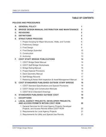
iTABLE OF CONTENTSTABLE OF CONTENTSPOLICIES AND PROCEDURESA.GENERAL POLICY1B.BRIDGE DESIGN MANUAL DISTRIBUTION AND MAINTENANCE2C.REVISIONS2D.DEFINITIONS2E.STRUCTURES PROCESS5F.1. Project Scoping for Major Structures, Walls, and Tunnels62. Preliminary Design63. Final Design94. Final Design Submittal105. Construction136. Archiving13CDOT STAFF BRIDGE PUBLICATIONS141. CDOT Bridge Detail Manual142. CDOT Staff Bridge Worksheets143. Bridge Rating Manual164. Project Special Provisions165. Deck Geometry Manual176. Staff Bridge Records177. Retaining & Noise Wall Inspection & Asset Management Manual18G. CDOT STANDARDS PUBLISHED OUTSIDE STAFF BRIDGE181. CDOT Standard Specifications and Special Provisions182. CDOT Design and Construction Manuals183. CDOT M & S Standard Drawings19H.STANDARDS PUBLISHED OUTSIDE CDOT19I.EXCEPTIONS19J.LOCAL AGENCY PROJECTS, DEVELOPER PROJECTS,AND ACCESS PERMITS WITHIN CDOT ROW201. General Services for All Local Agency Projects, DeveloperProjects, and Access Permits Within CDOT ROW202. Requirements for Local Agency Projects213. Requirements for Utility and Special Use Permits21CDOT Bridge Design ManualFebruary 2022
iiTABLE OF CONTENTSSECTION 1INTRODUCTION1.1 GENERAL REQUIREMENTS1-11.2 DEFINITIONS1-11.2.1Load and Resistance Factor Design (LRFD)1-11.2.2Culvert Definition1-11.2.3Glossary of Terms1-11.2.4Limit States1-41.3 DESIGN SPECIFICATIONS1-51.3.1Load and Resistance Factor Design (LRFD)1-51.3.2Load Factor Design (LFD)1-51.3.3Allowable Stress Design (ASD)1-5SECTION 2GENERAL DESIGN AND LOCATION FEATURES2.1 GENERAL2-12.2 LOCATION FEATURES2-12.2.1Alignment2-12.2.2Vertical Clearances2-22.2.3Horizontal Clearances2-22.2.4Criteria for Deflection2-42.2.5Sidewalks2-42.2.6Environmental Considerations2-52.3 AESTHETIC2-62.3.1General Requirements2-62.3.2Lighting2-72.3.3Form Liners and Veneers2-72.4 RAILING AND FENCING2-82.4.1Railing2-82.4.2Fencing2-102.5 RAILROAD REQUIREMENTS2-132.5.1General Requirements2-132.5.2Vertical Clearance2-132.5.3Horizontal Clearance2-132.5.4Construction Clearance2-132.5.5Protection and Screening2-142.5.6Collision2-14CDOT Bridge Design ManualFebruary 2022
iiiTABLE OF CONTENTS2.6 INSPECTION ACCESS2-142.7 FORMWORK2-162.8 UTILITIES2-162.9 FOUNDATION INVESTIGATION2-172.9.1General2-172.9.2Geotechnical Report Requirements2-172.9.3Code2-172.9.4Global Stability2-172.9.5Deliverable2-182.10 STRUCTURE SELECTION REPORT2-182.10.1General Requirements2-182.10.2Major Structures2-192.10.3Minor Structures2-202.10.4Wall Structures2-202.10.5Overhead Sign Structures2-212.10.6Tunnels2-212.10.7Accelerated Bridge Construction2-222.10.8Life Cycle Cost Analysis2-222.10.9Aesthetics2-222.11 HYDROLOGY AND HYDRAULICS2-222.11.1Drainage Report Requirements2-222.11.2Scour2-232.11.3Deck Drainage Requirements2-232.12 BRIDGE SECURITY2-242.13 APPROACH SLABS2-242.14 PIGEON PROOFING2-252.15 SPREAD FOOTING EMBEDMENT2-252.16 DAMAGE AVOIDANCE DETAILS2-252.17 DISSIMILAR METALS2-26SECTION 3LOADS AND LOAD FACTORS3.1 GENERAL REQUIREMENTS3-13.2 CODE REQUIREMENTS3-13.3 CONSTRUCTION LOADING3-1CDOT Bridge Design ManualFebruary 2022
ivTABLE OF CONTENTS3.4 DEAD LOADS3-13.4.1Stay-in-Place Metal Deck Forms3-13.4.2Wearing Surface3-13.4.3Utilities3-23.4.4Girder Concrete3-23.5 COLLISION LOAD3-23.5.1Policy3-23.5.2New Bridges3-23.5.3Existing Structures3-33.5.4Temporary Works3-33.6 VEHICULAR LIVE LOAD3-43.7 VEHICULAR LIVE LOAD ON CULVERTS3-43.8 DECK OVERHANG LOAD3-53.9 CENTRIFUGAL FORCES3-53.10 BRAKING FORCE3-53.11 FATIGUE LOAD3-63.12 STREAM FORCES AND SCOUR EFFECTS3-63.13 SEISMIC LOADING3-63.14 TEMPERATURE / THERMAL FORCES3-63.15 EARTH PRESSURES AND SETTLEMENT EFFECTS3-63.16 PEDESTRIAN LOADING3-73.17 BLAST LOADING3-73.18 WIND LOADS3-73.19 FENCE LOADS3-73.20 REFERENCES3-8SECTION 4STRUCTURAL ANALYSIS AND EVALUATION4.1 GENERAL REQUIREMENTS4-14.2 CODE REQUIREMENTS4-14.3 MODELING METHODS4-14.4 DEAD LOAD DISTRIBUTION4-24.5 LIVE LOAD DISTRIBUTION4-24.5.1Exterior Girder Live Load Distribution4-34.6 SKEW EFFECTS ON BRIDGES4-34.7 FOUNDATION STIFFNESS AND SOIL-PILE INTERACTION4-4CDOT Bridge Design ManualFebruary 2022
vTABLE OF CONTENTSSECTION 5CONCRETE STRUCTURES5.1 GENERAL REQUIREMENTS5-15.2 CODE REQUIREMENTS5-15.3 MATERIAL PROPERTIES5-15.3.1Concrete Classes5-15.3.2Modulus of Elasticity5-25.3.3Relative Humidity5-25.3.4Reinforcement5-25.3.5Prestressing Strand and Bars5-35.3.6Concrete Inserts5-45.4 REINFORCED CONCRETE5-45.4.1Bar Size Availability5-45.4.2Development and Splice Lengths5-45.4.3Clear Cover5-45.4.4Spacing5-55.4.5Corrosion Protection Requirements5-55.4.6Splash Zone Definition5-65.4.7Crack Control Factors5-65.4.8Mass Concrete5-65.4.9Seismic Detailing5-75.4.10Drilled Shaft and Round Column Shear Reinforcing5-75.4.11Pier Cap Reinforcing Details5-75.4.12Combination of Flexural and Axial Effects5-95.4.13Box Culverts5-95.5 PRESTRESSING5-95.5.1General5-95.5.2Pretensioned Concrete5-135.5.3Post-Tensioned Concrete5-175.6 LONGITUDINAL REINFORCEMENT FOR SHEAR5-205.6.1General5-205.6.2Direct Loading and Supports5-205.6.3Indirect Loading and Supports5-215.6.4Simply Supported Girder Ends5-22CDOT Bridge Design ManualFebruary 2022
viTABLE OF CONTENTS5.7 SIMPLE SPAN PRESTRESSED MADE CONTINUOUS5-225.7.1General5-225.7.2Age of Girder When Continuity Is Established5-235.7.3Degree of Continuity at Various Limit States5-235.8 PRECAST SPLICED BRIDGES5-235.8.1General5-235.8.2Girder Age Restrictions5-235.8.3Joints Between Segments5-245.8.4Details of Closure Joints5-245.8.5Segment Design5-245.8.6Consideration of Future Deck Replacement5-245.8.7Girder Camber, Haunch, and Dead Load Deflections5-245.9 CAST-IN-PLACE CONCRETE GIRDERS5-255.9.1General5-255.9.2Box Girder Bottom Slab Slope5-255.9.3Box Girder Formwork Load5-255.9.4Web Reinforcement5-255.10 SEGMENTAL BOX GIRDERS5-255.10.1General5-255.10.2Provision for Future Dead Load or Deflection Adjustment5-25SECTION 6STEEL STRUCTURES6.1 GENERAL REQUIREMENTS6-16.2 CODE REQUIREMENTS6-16.3 MATERIAL PROPERTIES6-16.3.1Steel Components6.4 FATIGUE AND FRACTURE 26.5 GENERAL DIMENSION AND DETAIL REQUIREMENTS6-36.5.1General6-36.5.2Dead Load Camber6-36.5.3Minimum Thickness of Steel6-56.5.4Diaphragms and Cross-Frames6-5CDOT Bridge Design ManualFebruary 2022
viiTABLE OF CONTENTS6.6 I-SECTION FLEXURAL MEMBERS6-56.6.1Composite Sections6.6.2Minimum Negative Flexure Concrete Deck Reinforcement 6-66.6.3Non-composite al Stiffeners and Cover Plates6-86.6.6Simple Made Continuous6-86.7 TUB/BOX-SECTION FLEXURAL ross-Section Proportion Limits6-86.8 CONNECTIONS AND SPLICES6-96.8.1Bolted Connections6-96.8.2Flange Splices6-96.8.3Welded Connections6-96.9 REFERENCES6-10SECTION 7ALUMINUM STRUCTURES7.1 GENERAL REQUIREMENTS7-17.2 CODE REQUIREMENTS7-1SECTION 8WOOD STRUCTURES8.1 GENERAL REQUIREMENTS8-18.2 CODE REQUIREMENTS8-1SECTION 9DECK AND DECK SYSTEMS9.1 GENERAL REQUIREMENTS9-19.2 CODE REQUIREMENTS9-19.3 PERFORMANCE REQUIREMENTS9-19.3.1Service Life9-19.3.2Maintenance Requirements9-29.4 ANALYSIS METHOD9-29.4.1General9-29.4.2Deck Design Tables9-3CDOT Bridge Design ManualFebruary 2022
viiiTABLE OF CONTENTS9.5 DECK THICKNESS9-99.6 LONGITUDINAL REINFORCEMENT9-99.6.1Minimum Required Reinforcing9-99.6.2Negative Moment Reinforcing9-99.7 DECK OVERHANG DESIGN9-109.7.1Overhang Requirements9-109.7.2Deck Overhang Loading and Design9-109.8 SKEWED DECK LIMITS9-119.8.1Transverse Reinforcement9-119.8.2Reinforced End Zones9-119.9 OVERLAYS9-129.10 139.11 DECK POURING SEQUENCE9-139.11.1Rate of Pour and Direction9-139.11.2Deck Pour Sequence Details9-139.11.3Diaphragms9-149.12 DECK JOINTS9-149.12.1Transverse Joints9-149.12.2Longitudinal Joints9-149.13 STAY-IN-PLACE FORMS9-149.13.1General9-149.13.2Concrete Stay-in-Place Forms9-159.13.3Metal Stay-in-Place Forms9-159.13.4Transparent Stay-in-Place Forms9-159.14 FULL DEPTH PRECAST CONCRETE DECK PANELS9-169.15 DECK DRAINS9-169.16 LIGHTS AND SIGNS ON DECK9-169.17 CONDUIT IN DECK9-169.18 ANTI-ICING SYSTEMS9-17SECTION 10FOUNDATIONS10.1 GENERAL SCOPE10-110.2 GEOTECHNICAL INVESTIGATIONS10-110.2.1Ring-Lined Split Barrel SamplerCDOT Bridge Design Manual10-1February 2022
ixTABLE OF CONTENTS10.3 Energy Measurements for Sampling Hammers10-110.4 LIMIT STATES AND RESISTANCE FACTORS10-210.4.1Service Limit State10-210.4.2Strength Limit State10-210.4.3Extreme Event Limit State10-210.5 SPREAD FOOTINGS10-210.5.1General10-210.5.2Footing Embedment10-210.5.3Tolerable Movements10-210.6 DRIVEN PILES10-310.6.1General10-310.6.2Geotechnical Design and Analysis10-510.6.3Top of Pile Fixity10-610.6.4Field Splice10-710.6.5Dynamic Testing10-810.6.6Plan Requirements10-810.6.7Load Testing10-810.7 DRILLED SHAFTS10-910.7.1General10-910.7.2Geotechnical Design and Analysis10-910.7.3Non-destructive Integrity Testing10-1010.7.4Load Testing10-1110.7.5Plan Requirements10-1110.8 REFERENCES10-12SECTION 11ABUTMENT, PIERS, AND RETAINING WALLS11.1 GENERAL REQUIREMENTS11-111.2 CODE REQUIREMENTS11-111.3 ABUTMENTS11-111.3.1Integral Abutments11-211.3.2Semi-integral Abutments11-711.3.3Seat Type Abutments11-911.3.4Tall Wall Abutments11-1311.3.5Geosynthetic Reinforced Soil Abutments11-1411.3.6Wingwalls11-2411.3.7Approach Slabs11-25CDOT Bridge Design ManualFebruary 2022
xTABLE OF CONTENTS11.4 PIERS11-2511.4.1IMulti-Column Piers11-2911.4.2Single Column (Hammerhead) Piers11-2911.4.3Solid Wall Piers11-2911.4.4Straddle Bent 1.5 RETAINING WALLS11-3111.5.1Cantilever Retaining Wall11-3211.5.2Counterfort Retaining Wall11-3411.5.3Mechanically Stabilized Earth Wall11-3411.5.4Drilled Shaft Walls11-3711.5.5Anchored Walls11-3711.5.6Soil Nail Walls11-3711.5.7Gravity Walls11-3811.5.8Landscape Walls11-3811.5.9Load Combinations11-3811.5.10Resistance Factors11-3911.5.11Collision with a Wall11-3911.5.12Global and Compound Stability11-4111.5.13Designer Responsibility for Walls11-4211.5.14Designer Responsibility for Using MSE WallWorksheets11-4211.5.15Designer Responsibility for Using Soil Nail WallWorksheets11-4311.5.16Seismic Design Requirements11-4311.6 DRAINAGE REQUIREMENTS11-4311.7 SHORING11-4311.8 REFERENCES11-44SECTION 12BURIED STRUCTURES AND TUNNEL LINERS12.1 GENERAL REQUIREMENTS12-112.2 CODE REQUIREMENTS12-112.3 GEOTECHNICAL REQUIREMENTS12-112.4 CONCRETE BOX CULVERTS12-112.4.1Design Criteria12-112.4.2Loading12-1CDOT Bridge Design ManualFebruary 2022
xiTABLE OF CONTENTS12.4.3Replacement12-212.4.4Stream Crossing12-212.4.5Pedestrian Crossing12-212.5 WILDLIFE CROSSING12-212.6 TUNNELS12-412.7 PIPES12-4SECTION 13RAILINGS13.1 GENERAL REQUIREMENTS13-113.2 CODE REQUIREMENTS13-213.2.1AASHTO LRFD13.2.2AASHTO Manual for Assessing Safety Hardware (MASH) 13-213.2.3FHWA Bridge Rail Requirements13.3 CDOT BRIDGE RAILS13-213-313-413.3.1Type 3 (Retired)13-413.3.2Type 4 (Retired)13-413.3.3Type 7 (Retired)13-413.3.4Type 8 (Retired)13-413.3.5Type 8R MASH13-513.3.6Type 10 (Retired)13-513.3.7Type 913-513.3.8Type 10 MASH13-513.4 COMBINATION VEHICULAR PEDESTRIAN RAILS13-513.5 PIER AND RETAINING WALL PROTECTION13-613.5.1Pier Protection13-613.5.2Retaining Wall Protection13-613.5.3Sound Barriers13-613.5.4Rail Anchor Slabs13-613.6 ATTACHMENTS TO BRIDGE RAIL SYSTEMS13-713.7 AESTHETIC TREATMENTS TO BRIDGE RAIL SYSTEMS13-713.8 RAILING ATTACHMENT TO HEADWALLS13-7SECTION 14JOINTS AND BEARINGS14.1 GENERAL REQUIREMENTS14-114.2 CODE REQUIREMENTS14-1CDOT Bridge Design ManualFebruary 2022
xiiTABLE OF CONTENTS14.3 UNIFORM TEMPERATURE MOVEMENT14-114.4 EXPANSION JOINTS14-114.4.1General14-114.4.2Design Guidelines and Selection14-214.4.3Small Movement Joints14-314.4.4Strip Seals14-514.4.5Modular Joints14-614.4.6Finger Joints14-614.4.7Cover Plates14-614.4.8Joint Headers14-714.4.9Expansion Joint Details14-814.5 BEARINGS14-814.5.1General14-814.5.2Design Guidelines and Selection14-814.5.3Thermal Movement14-914.5.4Additional Rotation Requirements14-914.5.5Design Coefficient of Friction Requirements14-914.5.6Bearing Inspection and Removal14-914.5.7Leveling Pads14-1014.5.8Type I Bearings14-1014.5.9Type II Bearings14-1014.5.10Type III Bearings14-1114.5.11Type IV and V Bearings14-1114.5.12Bearing Details14-1114.6 SHOP DRAWINGS14-12SECTION 15DESIGN OF SOUND BARRIERS15.1 GENERAL REQUIREMENTS15-115.2 CODE REQUIREMENTS15-115.3 AESTHETICS15-115.4 LOADS15-1SECTION 16 THROUGH SECTION 30CDOT Bridge Design ManualFebruary 2022
xiiiTABLE OF CONTENTSSECTION 31PEDESTRIAN STRUCTURES31.1 GENERAL REQUIREMENTS31-131.2 CODE REQUIREMENTS31-131.3 PERFORMANCE REQUIREMENTS31-131.3.1Service Life31-131.3.2Maintenance Requirements31-131.3.3Aesthetic Goals31-131.4 GEOMETRY AND CLEARANCES31-131.4.1Geometry31-131.4.2Vertical Clearances31-231.4.3Horizontal Clearances31-231.5 LOADS AND DEFLECTIONS31-331.5.1Live Loads31-331.5.2Collision31-431.5.3Deflection Limits31-431.5.4Vibration Limits31-431.6 FRACTURE CRITICAL DESIGNATION31-431.7 RAILING AND FENCING REQUIREMENTS31-431.8 COVERED/ENCLOSED STRUCTURES31-431.9 DECK31-531.10 LIGHTING31-531.11 DRAINAGE31-5SECTION 32SIGNS, LUMINARIES, AND TRAFFIC SIGNALS32.1 GENERAL REQUIREMENTS32-132.2 CODE REQUIREMENTS32-132.3 DESIGN CRITERIA32-232.3.1Loads32.4 BRIDGE MOUNTED STRUCTURES32-232-5SECTION 33PRESERVATION AND REHABILITATION OF STRUCTURES33.1 GENERAL REQUIREMENTS33-133.1.1Definitions of Preservation and Rehabilitation33-133.1.2Rehabilitation vs. Replacement Selection Guidelines33-133.1.3Required Inspection and Testing33-3CDOT Bridge Design ManualFebruary 2022
xivTABLE OF CONTENTS33.2 CODE AND PERFORMANCE REQUIREMENTS33-433.2.1Existing Structure Evaluation and Preservation Projects33-433.2.2Rehabilitation Projects33-533.3 REHABILITATION33-733.3.1General Requirements33-733.3.2Added Service Life33-733.3.3Acceptable Methods33-933.3.4Timber Structures33-1033.3.5Concrete for Repairs33-1033.4 BRIDGE WIDENING33-1033.4.1General Widening Requirements33-1133.4.2Design Considerations33-1133.5 BRIDGE DECK REPAIR AND REHABILITATION33-1333.5.1Chloride Induced Corrosion33-1333.5.2Susceptibility Index33-1433.5.3Selection of Corrosion Control Alternatives33-1533.6 CONCRETE REHABILITATION – EXCLUDINGBRIDGE DECKS33-1733.7 DECK REPLACEMENT33-1733.8 EXPANSION JOINT ELIMINATION33-1833.8.1Expansion Joints at Abutments33-1833.8.2Expansion Joints at Piers33-1933.9 BEARING REPLACEMENT33.9.1Structure Jacking Requirements33-1933-2033.10 BRIDGE RAIL REPLACEMENT33-2133.11 FATIGUE33-2133.11.1Load Induced Fatigue33-2133.11.2Distortion Induced Fatigue33-2133.12 CULVERTS33-2333.13 SCOUR CRITICAL STRUCTURES33-2333.13.1Evaluation of Existing Structures for Criticality33-2333.13.2Rehabilitation of Scour Critical Structures33-2333.13.3Structural Countermeasure Requirements33-2333.14 PAINTING OF STEEL STRUCTURES33.14.1Zinc Rich Paint SystemsCDOT Bridge Design Manual33-2333-24February 2022
xvTABLE OF CONTENTS33.15 BRIDGE PREVENTATIVE MAINTENANCE33-2533.15.1Program Objectives33-2533.15.2Bridge Preventative Maintenance Resources33-2633.15.3Bridge Preventative Maintenance Project Delivery33-2833.16 REFERENCES33-30SECTION 34PLANS34.1 GENERAL REQUIREMENTS34-1SECTION 35COST ESTIMATING AND QUANTITIES35.1 GENERAL REQUIREMENTS35-135.2 BID ITEMS35-135.3 PLANNING/CONCEPTUAL35-135.4 SCOPING35-235.5 PRELIMINARY / FIELD INSPECTION REVIEW (FIR)35-235.6 FINAL / FINAL OFFICE REVIEW (FOR)35-235.7 QUANTITY CALCULATIONS35-235.8 ACCURACY AND FORMAT35-3SECTION 36CONSTRUCTION36.1 GENERAL REQUIREMENTS36-136.2 CONSTRUCTION SUPPORT36-136.3 INQUIRIES DURING ADVERTISEMENT36-136.4 CONTRACTOR DRAWING SUBMITTALS36-236.4.1Shop Drawings36-236.4.2Working Drawings36-336.4.3Demolition and Girder Erection36-336.5 REQUESTS FOR INFORMATION (RFI)/REQUESTS FORREVISION (RFR)36.1.1As-Constructed Plans36-336-436.6 BRIDGE CONSTRUCTION REVIEWS, FINAL INSPECTION36-436.7 ARCHIVING36-5CDOT Bridge Design ManualFebruary 2022
xviTABLE OF CONTENTSSECTION 37QUALITY ASSURANCE AND QUALITY CONTROL37.1 GENERAL REQUIREMENTS37-137.2 PURPOSE37-137.3 DEFINITIONS37-137.4 QUALITY MANAGEMENT PLAN37-437.5 QUALITY CONTROL/QUALITY ASSURANCE PROCEDURES37-4SECTION 38ALTERNATIVE DELIVERY38.1 GENERAL REQUIREMENTS38.1.1Delivery Method Evaluation38-138-138.2 DESIGN-BID-BUILD38-138.3 CONSTRUCTION MANAGER/GENERAL CONTRACTOR38-138.4 DESIGN-BUILD AND STREAMLINED DESIGN-BUILD38-238.4.1Owner Representation – Preliminary Design38-338.4.2Owner Representation – Delivery38-338.4.3Contractor’s Designer38-338.5 ALTERNATIVE BRIDGE DESIGN SPECIFICATION38-4SECTION 39ACCELERATED BRIDGE CONSTRUCTION39.1 GENERAL INFORMATION39-139.2 ABC EVALUATION OVERVIEW39-139.2.1Background39-139.2.2ABC Evaluation Process39-139.3 ABC MATERIALS AND RESOURCE GUIDANCE39.3.139-2ABC Evaluation and Decision Matrix Workflow- Attachment A39-239.3.2Pre-scoping ABC Rating – Attachment B39-439.3.3ABC Matrix – Attachment C39-639.3.4ABC AHP Decision Tool Software39-639.4 OTHER RESOURCESCDOT Bridge Design Manual39-6February 2022
xxLIST OF TABLESLIST OF TABLESSECTION 3LOADS AND LOAD FACTORSTable 3-1:Fence Loads3-8SECTION 5CONCRETE STRUCTURESTable 5-1:Common Concrete Classes and Strengths5-1Table 5-2:Typical CIP Concrete Applications5-1Table 5-3: Minimum Lap Length for Epoxy-Coated Slab, Wall, orFooting Bars Spaced at 6.0 in. min. on Center with 2.0 in. min.Clear Cover and f’c 4.5 ksi5-4Table 5-4: Minimum Lap Length for Epoxy-Coated Slab, Wall, orFooting Bars Spaced at 6.0 in. min. on Center with 1.0 in. min.Clear Cover and f’c 4.5 ksi5-4Table 5-5:Minimum Clear Cover for Drilled Shafts on Bridges5-5Table 5-6:Standard CBT Properties5-11SECTION 9DECK AND DECK SYSTEMSTable 9-1: CDOT Standard CBT GirderLoad and Resistance Factor Design (fy 60 ksi)9-4Table 9-2: Rolled Steel Beams/Steel Plate Girders (12 in. [min.] wide top9-5flange) Load and Resistance Factor Design (fy 60 ksi)Table 9-3: CDOT Standard CBT Girder Load and Resistance Factor Design9-6(fy 100 ksi)Table 9-4: Rolled Steel Beams/Steel Plate Girders (12 in. [min.] wide topflange) Load and Resistance Factor Design (fy 100 ksi)9-7SECTION 10FOUNDATIONSTable 10-1:Calculated Embedments10-7SECTION 11ABUTMENT, PIERS, AND RETAINING WALLSTable 11-1:Limiting Structure Lengths for Integral Abutments11-2Table 11-2:Load Factors for Retaining Wall Design11-39CDOT Bridge Design ManualFebruary 2022
xxiLIST OF TABLESSECTION 32SIGNS, LUMINARIES, AND TRAFFIC SIGNALSTable 32-1:Wind Speed Data at Other Mean Recurrence Intervals32-5Table 32-2:Torque and Tension Limits32-7SECTION 33PRESERVATION AND REHABILITATION OF STRUCTURESTable 33-1:Maintenance Painting Frequencies33-25Table 33-2:BPM Joint Replacement Matrix33-27SECTION 35COST ESTIMATING AND QUANTITIESTable 35-1:Contingency and Quantity Accuracy Percentage35-4Table 35-2:Summary of Quantities Table Rounding35-5CDOT Bridge Design ManualFebruary 2022
xviiLIST OF FIGURESLIST OF FIGURESSECTION 2GENERAL DESIGN AND LOCATION FEATURESFigure 2-1: Bridge Clearances – High Speed RoadwayFigure 2-2: Bridge Clearances – Low Speed RoadwayFigure 2-3: Bridge Clearances with MSE Retaining WallFigure 2-4: Standard Sidewalk DetailsFigure 2-5: Vertical Concrete Surface DetailsFigure 2-6: Bridge Rail Types 9 and 10 MASHFigure 2-7: Fencing TypesFigure 2-8: Drop-Off ProtectionFigure 2-9: Access Door Detail2-32-32-42-52-82-92-112-122-15SECTION 3LOADS AND LOAD FACTORSFigure 3-1:Colorado Permit Vehicle3-4SECTION 4STRUCTURAL ANALYSIS AND EVALUATIONFigure 4-1:Skew Angle Definition4-3SECTION 5CONCRETE STRUCTURESFigure 5-1:Splash Zone5-6Figure 5-2: Pier Caps in Post-Tensioned Bridges with a Skew Angle of20 Degrees or Less and Deck Reinforcing Parallel to Cap5-7Figure 5-3:Figure 5-4:Pier Caps in Post-Tensioned Bridges with a Skew AngleGreater Than 20 Degrees and Deck Reinforcing NotParallel to Cap5-8Pier Caps in Precast Girder Bridges withConstant-Depth Cap5-8Figure 5-5:Pier Caps in Precast Girder Bridges with Variable-Depth Cap(side steel not shown for clarity)5-9Figure 5-6: Standard U Girder Dimensions5-11Figure 5-7: Through-the-Thickness Steel at Construction Joints5-19Figure 5-8:Plan View of Through-the-Thickness Reinforcingat a Web Thickness TransitionFigure 5-9:Figure 5-10:Examples of Direct Supporting and Loading ConditionsIndirect Support/Loading – Integral Pier CapCDOT Bridge Design Manual5-205-215-22February 2022
xviiiLIST OF FIGURESSECTION 6STEEL STRUCTURESFigure 6-1:Recommended Fit Conditions6-4Figure 6-2:Deck Overhang Bracket6-7SECTION 9DECK AND DECK SYSTEMSFigure 9-1:Deck Design Table Detail9-8Figure 9-2:Splayed Deck Reinforcing9-11Figure 9-3:Skewed Deck Reinforcing Placement9-12Figure 9-4:Acute Corner Reinforcing9-12SECTION 10FOUNDATIONSFigure 10-1:Pile Fixity10-6Figure 10-2:Moment Inflection Point and H-Pile Field Splices10-7SECTION 11ABUTMENT, PIERS, AND RETAINING WALLSFigure 11-1:Integral Abutment on H-Piles11-5Figure 11-2:Integral Abutment on Drilled Shafts11-7Figure 11-3:ISemi-Integral Abutment (Alternative 1)11-8Figure 11-4:Semi-Integral Abutment (Alternative 2)11-10Figure 11-5:Seat Type Abutment11-12Figure 11-6:Tall Wall Abutment11-14Figure 11-7:GRS Abutment (Cut Case)11-19Figure 11-8:GRS Abutment (Fill Case)11-20Figure 11-9:Integrated Girder Seat with Footer11-21Figure 11-10: Separated Girder Seat with Footer11-21Figure 11-11: Transition Zone Behind Abutment Backwall (With ExpansionJoint, Concrete Slab, and Roadway Pavement)11-22Figure 11-12: Transition Zone Behind Abutment Backwall (With AsphaltPavement Approach Slab and No Expansion Joint)11-23Figure 11-13:Column-Drilled Shaft Connection Details11-28Figure 11-14:Footing on Pile11-30Figure 11-15:Shear Key11-33CDOT Bridge Design ManualFebruary 2022
xixLIST OF FIGURESFigure 11-16:Cantilever Retaining Wall Reinforcement11-33Figure 11-17:Soil Nail Wall in Future Bridge Widening Area11-38Figure 11-18:Lateral Collision Distribution11-40Figure 11-19:Global and Compound Failure Planes11-41SECTION 12BURIED STRUCTURES AND TUNNEL LINERSFigure 12-1:Minimum Deer and Elk Underpass Design Dimensions12-3SECTION 14JOINTS AND BEARINGSFigure 14-1:Silicone Seal14-3Figure 14-2:Compression Seal - Elastomeric14-4Figure 14-3:Compression Seal - Foam14-5SECTION 31PEDESTRIAN STRUCTURESFigure 31-1:CDOT Legal Load Type 331-3SECTION 32SIGNS, LUMINARIES, AND TRAFFIC SIGNALSFigure 32-1:Partial Special Wind Region Map (300 year MRI)32-4Figure 32-2:Sign Alignment for Curved Roadways32-6SECTION 33PRESERVATION AND REHABILITATION OF STRUCTURESFigure 33-1:Asphalt Thickness Verification Detail33-4Figure 33-2:Optimal Corrosion Control Based on Susceptibility Index33-15Figure 33-3:Expansion Joint Relocation33-19Figure 33-4:Differential Deflection33-22Figure 33-5:Web Gap Distortion33-22SECTION 39ACCELERATED BRIDGE CONSTRUCTIONFigure 39-1:ABC Decision Matrix WorkflowFigure 39-2: ABC MatrixCDOT Bridge Design Manual39-339-7February 2022
CDOT Bridge Design Manual February 2022 . SECTION 1 . INTRODUCTION . 1.1 GENERAL REQUIREMENTS 1-1 1.2 DEFINITIONS 1-1 . 1.2.1 Load and Resistance Factor Design (LRFD) 1-1 1.2.2 Culvert Definition 1-1 1.2.3 Glossary of Terms 1-1 1.2.4 Limit States 1-4 1.3 DESIGN SPECIFICATIONS 1-5 1.3.1 Load and Resistance Factor Design (LRFD) 1-5
