Transcription
Transitioning to LRFD Bridge Design Using DCALCChapter 5: Transitioning to LRFD Bridge Design Using DCALC*By Karl Hanson, S.E., P.E.December 20075.1 Introduction:The new AASHTO LRFD bridge design specification represents a major overall inAASHTO’s design specification. This effort, which began in the late 1980’s and early1990’s, has become federally mandated nationwide. In one giant fell swoop, the LRFDcommittees cleaned-house, replacing large sections of the specifications with the lateststate-of-the-art methods. The emphasis is on rational (i.e., statistically verifiable) methodsand mathematically consistent safety factors. LRFD is an intellectual leap, a broaderview, with greater subtlety and intricacy than the previous specifications.The purpose of this chapter is to compare side-by-side the major changes between theStandard Specs and the LRFD Spec. Experienced designers can benefit from a side-byside comparison, to get a better sense of continuity between the two specifications.This paper does not intend to interpret or explain the theory behind the LRFD code. Theobjective here is to show designers various links between the codes. Learning LRFD willrequire some effort on your part. You cannot avoid reading the LRFD Specification.Design codes seem to be getting bigger and more complicated every year. Personally,I’ve found that the only way to manage and organize this information is by using thecomputer as a robotic assistant - otherwise I simply can’t keep up with the changes. I’veclumsily found my way through the LRFD forest and have implemented the changes intoDCALC software. DCALC calculations document the relevant sections of the LRFDspecification. It is my hope that DCALC will also help to serve you as a guide throughthe LRFD forest.5.2 The Key Differences Between the Standard Spec’s and the LRFD Spec’s:You will first need to learn the equivalencies between the two specifications. In otherwords: What we call “A” in the Standard Spec’s is now called “B” in LRFD. A lot ofconcepts have been renamed. A lot of concepts are “sort of the same”, but not quite.After identifying “the meat” of the changes, the next task is to identify what has been rewritten and reorganized. This is the clincher that will confound many of you LRFD hasentirely rearranged the presentation of AASHTO’s bridge specification. Everything is ina different place! (Remember the game “Twister”? It’s a lot like that.)Another caveat: Many equations that were in the Standard Specification that were writtenin units of “psi” have been changed into units of “ksi”, giving equations a differentappearance. I’ll try to identify the important equations which look entirely different in thetwo specifications but which actually mean the same thing. Most variables have beenrenamed in the new LRFD specification. There is also a heavy usage of mathematicalsymbols.* DesignCalcs, Inc. – Structural Engineering Software (www.dcalc.us)p.5-1
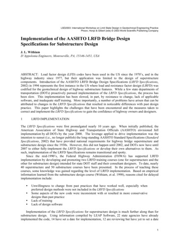
Transitioning to LRFD Bridge Design Using DCALC5.3 Live Loadings5.3.1 Live Loading Vehicles:AASHTO Standard Specification Design Live Loads:Using the Standard Specification, a bridge is analyzed for either truck loading or laneloading on the structure, but never in combination.AASHTO LRFD Specification Design Live Loads:Comparing the sketches, we see that “HS-20” and “HL-93” is the same vehicle. Laneloadings are different, because LRFD does not apply concentrated loads. Using LRFD, the effects of one truck or tandem plus lane loading are combined For computing negative moments, LRFD considers a case with 90% of two trucksspaced a minimum distance of 50 feet apart, plus 90% lane loading.p.5-2
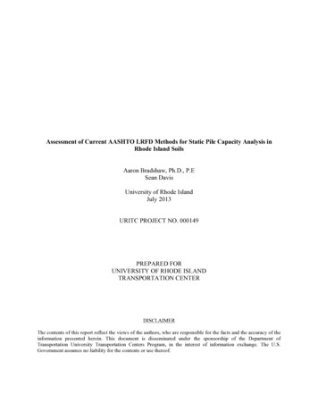
Transitioning to LRFD Bridge Design Using DCALC5.3.2 Live Loading Example BridgeTo illustrate the differences in live loading application techniques, we will consider howa generic two span bridge might be analyzed. This hypothetical bridge could be a steelbeam or plate girder bridge, or a prestressed concrete bridge. The objectives here will beto determine the maximum positive moment in the left span and the maximum negativemoment at the center pier.Influence lines (*) show how we need to place live loads. Regardless of which spec weuse, the same methods for engineering analysis (influence lines in this case) need to beused to compute force effects. For maximum positive moment, we will need to place loads in the “ ” region,which in case is in the left span.For maximum negative moment, we can place the loads in any “ ” region, whichin this particular bridge is along the entire structure length.Loads are placed for maximum effects, by finding the maximum influence coefficient fora particular force effect, and then placing the load at that ordinate.(* The easy trick for visualizing influence lines is to imagine how a beam will bend if a hinge is placed atthe point of influence)p.5-3
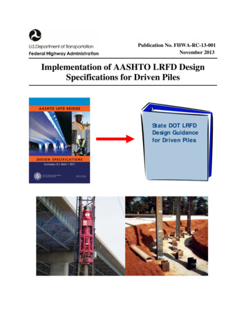
Transitioning to LRFD Bridge Design Using DCALC5.3.2 Live Loading Example: A 2 Span Bridge Loaded for Max Positive MomentThe below sketches show a two span bridge with live load positioned for maximumpositive moment in the left span:AASHTO Standard Specifications Live Load Cases:AASHTO LRFD Specifications Live Load Load Cases:The major difference between the two specifications is that with LRFD, the truck ortandem loads are combined with the lane loads. Although it would be impossible to placea lane load in the same space as a truck, for LRFD analysis we allow this to happen.p.5-4
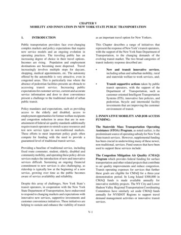
Transitioning to LRFD Bridge Design Using DCALC5.3.2Live Loading Example: A 2 Span Bridge – Loading for Maximum M negativeThe below sketches show a two span bridge with live load positioned for maximumnegative moment at the pier:AASHTO Standard Specifications Live Load Cases:AASHTO LRFD Specifications Live Load Load Cases:p.5-5
Transitioning to LRFD Bridge Design Using DCALC5.3.3Fatigue Live Loading Vehicle:AASHTO Standard Specification Fatigue Loading: Fatigue stress range limits are based on the same loadings that are used tocompute the design moments and shears.AASHTO LRFD Specification Fatigue Loading: Fatigue stress range limits are based on using an HL-93 truck, but with constant30 feet axle spacing. For this loading, only one truck is applied to the bridge (without combining thedesign lane load) A 15% impact factor (“dynamic load allowance”) is applied to the fatigue loadcase (compared to the 33% that is used in the determination of design momentsand shears)p.5-6
Transitioning to LRFD Bridge Design Using DCALC5.3.4How DCALC Analyzes Live Loads:Like most bridge analysis programs, DCALC’s “CBRIDGE” program computes live loadmoments and shears by computing influence coefficients at every tenth point on thebridge. CBRIDGE constructs a finite element model consisting of ten beam elements perspan. CBRIDGE places a 1 kip load at each point and computes the moments andshears at all other points due to that 1 kip load. These values are saved internallyto the program as influence coefficients. For every point, to determine the maximum and minimum moments and shears,CBRIDGE positions the live load truck, tandem and lane loads to producemaximum and minimum effects, using the influence coefficients. Several truckload positions are considered in the solution for each of the points, and axlespacing is adjusted for maximum force effects.One of the key differences in the live load analysis between the Standard Specificationsand the LRFD Specifications concerns section properties used for the analysis of steelcomposite beams. Using the Standard Specifications, it is customary to use non-composite sectionproperties in the negative moment regions, for computing the stiffness of thebeams for live load analysis. However, using the LRFD Specifications, the beams are modeled as compositethroughout the length of the bridge – even in the negative moment regions. (Referto LRFD Section 6.10.1.2)CBRIDGE approaches the live load analysis using both of the above techniques.p.5-7
Transitioning to LRFD Bridge Design Using DCALC5.4 Live Load Distribution Factors5.4.1 Live Load Distribution Factor ExampleAnother major difference between the two specifications is how live load distributionfactors are computed. To illustrate, live load distribution factors will be computed for a 2span bridge with the below deck cross-section:In this example, the bridge will consist of two 120 feet long spans, supported bycontinuous steel plate girders. Distribution factors for beam “B2” will be computed.AASHTO Standard Specification Live Load Distribution Factor:DF S/5.5(Table 3.23.1) 9.75/5.5 1.77 wheels per beamx 1 lane/2 wheels 0.886 lanes per beamAASHTO LRFD Specification Live Load Distribution Factors:(Refer to LRFD Table 4.6.2.2b-1 for LL Moment Distribution Factors)For one design lane loaded,DF Moment 0.06 (S/14)0.4 * (S/L)0.3 * (K/(12*L*ts3))0.1 0.06 (9.75/14)0.4 * (9.75/120)0.3 * 1.02 0.475 lanes/beamFor two or more design lane loaded,DF Moment 0.075 (S/9.5)0.6 * (S/L)0.2 * (K/(12*L*ts3))0.1 0.06 (9.75/9.5)0.6 * (9.75/120)0.2 * 1.02 0.702 lanes/beam (Governs)In the above, the term “(K/(12*L*ts3))0.1” has been set equal to 1.02, based on studiesmade by the Illinois Department of Transportation. (IDOT Bridge Manual, sec. 3.3.1).(Refer to LRFD Table 4.6.2.2.3a-1 for LL Shear Distribution Factors)For one design lane loaded,DF Shear 0.36 S/25 0.36 9.75/25 0.75 lanes per beamFor two or more design lanes per beam,DF Shear 0.2 S/12 – (S/35)2.0 0.2 9.75/12 – (9.75/35)2.0 0.934 lanes per beam (Governs)p.5-8
Transitioning to LRFD Bridge Design Using DCALC5.4.1 How to Use DCALC To Compute Live Load Distribution FactorsDCALC’s “LOADER” program computes live load distribution factors for both StandardSpecifications and LRFD Specifications. LOADER reads geometrical information about a bridge collected fromDCBRIDGE. (You will need to run DCBRIDGE before LOADER)LOADER computes distribution factors for all beams, for both specifications.At the user’s option, LOADER will use IDOT’s “simplified” values for theterm“(K/(12*L*ts3))0.1”, or the user can enter a value directly.LOADER outputs detailed calculations for one of the beams, for checkingpurposes. However, distribution factors for all beams are computed and saved inthe output, for use by the other DCALC program.LOADER prints all distribution factors side-by-side, for easy comparisonExample LOADER Output5.5 Impact FactorsWhat was previously called “Impact” has been renamed “Dynamic Load Allowance” inthe LRFD specification.AASHTO Standard Specification Impact Formula (Stand. Spec. Article 3.8.2):I 50/(L 125) 30% maximumWhere L span lengthExample: For L 120 feet, I 50/(120 125) 20.4%AASHTO LRFD Specification Dynamic Load Allowance, IM (LRFD Section 3.6.2):For design moments and shears,IM 33%For fatigue and fracture moments and shears,IM 15%p.5-9
Transitioning to LRFD Bridge Design Using DCALC5.6 Longitudinal ForcesThe previous term, “Longitudinal Forces” has been renamed “Braking Force” in theLRFD Specification.AASHTO Standard Specifications Longitudinal Forces (Stand. Spec. Article 3.9)LF 5% x (0.64 k/ft x Structure Length 18 k Concentrated Force)Example: 2 spans, each 120 feet long 240 feet (total)LF 5% x (0.64 k/ft x 240 ft 18 k) 8.58 kAASHTO LRFD Braking Force, BR (LRFD Spec. Article 3.6.4):The greater ofBR1 25% x Design Truck 25% x 72 k 18 kBR2 25% x Design Tandem 25% x 50 k 12.5 kBR3 5% x (0.64 k/ft x Structure Length 72 k Design Truck)BR4 5% x (0.64 k/ft x Structure Length 50 k Design Tandem)Example: 2 spans, each 120 feet long 240 feet (total)BR1 18 k (Governs)BR2 12.5 kBR3 5% x (0.64 k/ft x 240 ft 72 k) 11.28 kBR4 5% x (0.64 k/ft x 240 ft 50 k) 10.18 kp.5-10
Transitioning to LRFD Bridge Design Using DCALC5.7 Loading Name DifferencesIn many cases, the LRFD Specifications use different naming conventions for basic loadcases than were used previously.AASTHO Standard Specification LoadDead Load (D)Stream Pressure (SF)AASHTO LRFD Specification LoadDC – dead load of structureDW- dead load of wearing surface andutilitiesLL – vehicular live loadIM – vehicular dynamic load allowanceBR – vehicular braking forcesCE – vehicular centrifugal forcem - multiple presence factor (*)WS – wind on structureWL – wind on live loadTG – temperature gradientTU – uniform temperatureWA – water load and stream pressureIce Pressure (ICE)IC – ice loadEarth Pressure (E)Buoyancy (B)EH – horizontal earth pressureES – earth surcharge loadEV – vertical earth pressure(Classified as a “WA” uplift force)Earthquakes (EQ)EQ – earthquake effectShrinkage (S)SH – shrinkageLive Load (L)Impact (I)Longitudinal Forces (LF)Centrifugal Forces (CF)Lane Load Reduction FactorWind Load (W)Wind on Live Load (WL)Thermal Forces (T)(*) “multiple presence factor” is not exactly the same as “Lane Load Reduction Factor”,but is somewhat related.p.5-11
Transitioning to LRFD Bridge Design Using DCALC5.8 Load Factors for Permanent LoadsPermanent loads (DC, DD, DW, EH, EV, ES) require separate load factors,”γp”, whichare given in LRFD Table 3.4.1-2, copied below:For the design of superstructures, one of the more important distinctions in the abovetable is the separation of dead loads, “DC” and “DW”. Rather than simply applying oneload factor to all dead loads, as was previously done, the designer will need to break-outthe dead load due to the wearing surface and use a different load factor.For the design of substructures, the designer will need to consider maximum andminimum load factors for EH, EV and ES as well. There are potentially many loadcombinations that can be considered. Some interpretation and guesswork appears to benecessary in deciding which ”γp” to use for the substructure design, in order to minimizethe number of calculations.p.5-12
Transitioning to LRFD Bridge Design Using DCALC5.9 Group LoadingsAASHTO Standard Specification Group Loadings:AASHTO LRFD Specification Group Loadings:p.5-13
Transitioning to LRFD Bridge Design Using DCALC5.9– Group Loadings (Cont’d)The differences in group loadings between the two specifications is one of the moredifficult things to grasp at first. Perhaps the best way to explain is to show how to usethese group loadings for different design situations:Design Situation: Steel Beam DesignUsing the Standard Spec’s, the following group loadings will need to be checked:For ultimate strength check, Group I LFD 1.3 x (D 1.67 x (L I))For overload check (for permit vehicles),OVERLOAD D 5(L I)/3 (Stand. Spec. Art. 10.57)For fatigue check, Group I Service D (L I)Using the LRFD Spec’s, the following group loadings will need to be checked:For ultimate strength check,STRENGTH I 1.25xDC 1.5xDW 1.75 x (LL IM) (using IM 33%)For “overload” check (for permit vehicles, but no longer called “overload”),SERVICE II DC DW 1.30 x (LL IM) (using IM 33%)For fatigue check,FATIGUE I 0.75 x (LL IM) (using IM 15%)Design Situation: Prestressed Concrete Beam DesignUsing the Standard Spec’s, the following group loading will need to be checked:For checking stresses in beam, Group I Service D (L I)For ultimate strength check, Group I LFD 1.3 x (D 1.67 x (L I))Using the LRFD Spec’s, the following group loadings will need to be checked:For checking stresses in beam,SERVICE III DC DW 0.8x(LL IM)For ultimate strength check,STRENGTH I 1.25xDC 1.5xDW 1.75 x (LL IM) (using IM 33%)Design Situation: Concrete Pier DesignUsing the Standard Spec’s, it is straight forward which group loadings to apply: Check allowable pile loads and soil pressures using Groups I thru X ServiceLoads Design reinforcing for using Groups I thru X Factored LoadsUsing the LRFD Spec’s, some interpretation is required for determining what grouploading cases are applicable. The principal concern is which of the “γp” factors (LRFDTable 3.4.1-2) to apply for permanent loads for maximum and minimum effects.An issue of controversy is the elimination of allowable soil stresses and allowable pileloads in the LRFD design. The LRFD approach is to design foundations for ultimatepressures and ultimate pile reactions based on factored loads. Issues of serviceability (i.e.,settlement) are different LRFD load cases altogether.p.5-14
Transitioning to LRFD Bridge Design Using DCALCBecause historically designers are so used to approaching foundation design based inservice load methods, most of us will require some adjustment. For designers, one of thenice things about using “allowable pressures” is that in some cases pressure values arechosen to limit settlement, thereby “killing two birds with one stone”. Foundation designby LRFD appears to require additional work on the part of the structural engineer and thesoils engineer.5.9.1How DCALC Uses Group LoadingsDCALC’s steel beam program, “BRIJBEAM”, and the prestressed concrete beamprogram, “PCBRIDGE”, have both incorporated the applicable group loadings requiredfor the two specifications.DCALC’s pier design program, “PIER”, uses the straight forward group loadings forStandard Spec designs. For LRFD design, the below group loadings are used:p.5-15
Transitioning to LRFD Bridge Design Using DCALC5.10 A Sample Comparison of the Two Concrete Design Specifications:AASTHO Standard SpecificationsStress units in “PSI”Shrinkage Strain:8.7.4εsh 0.0002Modulus of Elasticity:Ec 57,000(fc’)1/2Modulus of Rupture:Normal Wt, fr 7.5*(fc’)1/28.78.15.2.1.1AASHTO LRFD SpecificationsStress units in “KSI”Shrinkage Strain:5.4.2.3In absence of accurate data,5.4.2.3.1εsh 0.0002 after 28 daysεsh 0.0005 after 1 yearNew Coefficients foraccurate analysis:Creep coefficient,ψ(t,ti) 1.9kskhckfktdti-.118Shrinkage Strain:εsh kskhckfktd0.48x10-3Modulus of Elasticity:Ec 1,820(fc’)1/2Modulus of Rupture:Normal Wt, fr 0.24*(fc’)1/2Normal Wt, fr 0.37*(fc’)1/2Normal Wt, fr 0.20*(fc’)1/2Strength reduction factors,Flexure, φ 090Shear, φ 0.85Axial, with spirals, φ 0.75with ties, φ .70Bearing, φ 0.708.16.1.2.2Maximum usable concretecompression strain:εs 0.0038.16.2.3Maximum Reinforcement ofFlexural Members:ρmax 0.75ρb8.16.3.1Minimum Reinforcement ofFlexural Members:φMn 1.2Mcror 1.33Mreq’d8.17.1.1Eq. 8-628.17.1.2Resistance factors,Flexurenon-prestressed, φ 0.90prestressed,φ 1.00Shear, φ 0.90Axial, φ 0.75Bearing, φ 0.70Maximum usable concretecompression strain:εs 0.003 if unconfinedbut εs can exceed 0.003 ifconfinedMaximum Reinforcement(Article Deleted in 2005.Previously placed a max.limit c/de 0.42)Minimum Reinforcement ofFlexural Members:φMn 1.2Mcror r use in Art.5.7.3.4 and5.7.3.6.2For use in Art.5.7.3.3.2For use in .3.3.2-1p.5-16
Transitioning to LRFD Bridge Design Using DCALCAASTHO Standard Specifications(no strut-and-tie provision)Shear Strength Provided byConcrete:Vc 2*(fc’)1/2*bw*d8-49Fatigue Stress Limitsff 21-0.33fmin 8(r/h)8.16.8.3Distribution of FlexuralReinforcementfs z/(dcA)1/3 0.6fy8.16.8.4(no torsion design spec’s)AASHTO LRFD SpecificationsStrut-and-Tie Modeling5.6.3(An entirely new approach)Shear Stress on Concrete:5.8.2.9(Sectional Design Model)Vc 0.316β*(fc’)bwdv if thesimplified procedure is used(the “simplified” procedurefor non-prestressed membersis essentially the same as theprevious spec.)5.8.3.1Vc the lesser of Vci and Vcwif the more complexprocedures are used.5.8.3.4.25.8.3.4.1(the more complex methodprocedures appear to beintended for prestressedmembers. This methodrequires the a calculation of astrain longitudinal factor “β”using an iterative approach)Fatigue Limit State5.5.3.2Reinforcing Barsff 24-0.33fminPrestressing Tendons18 ksi for R 30 ft and10 ksi for R 12 ft(note: “z” factor has been5.6.3.6eliminated!)Strut-and-Tie Crack ControlReinforcement:use ρ 0.003*AgFor Flexural And AxialEffects:Spacing of bars nearest thetension face,s 700γc/(bsfss)-2*dcTorsion Design:(new to the specification)5.7.3.4-15.8.2.1p.5-17
Transitioning to LRFD Bridge Design Using DCALC5.11 A Sample Comparison of the Two Steel Design Specifications:AASTHO Standard SpecificationsStress units in “PSI”Depth Ratios:10.5depth/span 1/25Composite girders,total depth/span 1/25beam depth/span 1/30AASHTO LRFD SpecificationsStress units in “KSI”Optional Criteria for Span2.5.2.6.3to-Depth Ratios:Composite beam slab depth Table 2.5.2.6.3dmin 0.04*L simple span1dmin 0.032*L continuousComposite beam depthdmin 0.033*L simple spandmin 0.027*L continuousDeflectionVehicular, /Span 1/800Vehicular and pedestrian, / Span 1/100010.610.6.2Allowable Fatigue StressRanges:(see Tables 10.31.1A & B)The fatigue stress is basedon the same types of designloadings considered in thedetermination of moments.10.3.1Limiting Lengths ofMembers:Compression members,KL/r 120 (Main members)KL/r 140 (secondary)10.7For curved steel girdersystems,span/depth 25Criteria for Deflection(optional)Vehicular, Span/800Vehicular and pedestrianload, Span/10002.5.2.6.2Load-Induced Fatigueγ( f) ( F)n6.6.1.26.6.1.2.2-1( F)n (A/N)1/3 1/2( F)THin whichN (365)(75)n(ADTT)SLThe fatigue stress range isbased on the fatigue truck,using the FATIGUE loadingin Table 3.4.1-1. Note thatthe designer will need toconsider the ADTT in asingle lane.Limiting Slenderness Ratio:6.6.1.2.5-16.6.1.2.5-26.9.3Compression members,KL/r 120 (Main members)KL/r 140 (secondary)p.5-18
Transitioning to LRFD Bridge Design Using DCALCAASTHO Standard SpecificationsSplices:10.18Design capacity of splice not lessthan the larger of average of design forces strength of the beam 75% strength of beamCompression Flange WidthCriteria:b 0.2 web depth (preferred)but in no case b 0.15 web depthCompression Flange CompactCriteria:b/t 4,100/(Fy)1/2whereb flange width (not half-width)10.48Web thickness Compact Criteria:D/tw 19,230/(Fy)1/210.48.1.1Eq. 10-94D/tw 4.68(b/t) 33,650/(Fy)1/2Spacing of Lateral Bracing forCompactness:Lb/ry (3.6- 2.2*M1/Mu))x106/FyEq. 10-9510.48.1.110.48.1.1Eq. 10-93Eq. 10-96AASHTO LRFD SpecificationsConnections and Splices:6.13.1Design capacity of splice notless than the larger of average of designforces resistance ofthe beam 75% resistance of beam(various requirements aresimilar, but equations in adifferent format.)Flange Proportions:6.10.2.2bf/(2tf) 12bf D/6tf 1.1twPlate Buckling Coefficient for 6.9.4.2half-width of flanges:b/t k*(E/Fy)1/26.9.4.2-1whereb flange half-widthTablek 0.566.9.4.2-1Also,b/t 0.64*(kc*E/Fy)1/2where6.9.4.2-2kc 4/(D/tw)1/26.9.4.2-4Plate Buckling Coefficient for 6.9.4.2web:b/t k*(E/Fy)1/26.9.4.2-1whereb web depth (clear distance)Tablek 1.496.9.4.2-1(A similar provision was in the1994 LRFD provision, as6.10.5.2.3. The currentprovision uses a differentpresentation.)Lateral Torsional BucklingResistance:A different approach. “Fnc“ isdetermined based on bracedlength, Lb, falling withinranges Lb Lp, Lp Lp Lr, orLb Lr(see code for equations)6.10.8.2.3p.5-19
Transitioning to LRFD Bridge Design Using DCALC5.12 ConclusionThe above comparison of various formulas should give a flavor of the differencesbetween the codes. There are many, many equations in the LRFD specification that couldbe listed in tables similar to above. As previously stated, this paper is meant to givedesigners only a flavor of the changes.Upon reading the LRFD spec, you will come away impressed by the body of knowledgecollected in one volume. It is obviously “state of the art”, more theoretically correct andintellectual. Some very smart people must have been involved in writing this largevolume.From my own perspective as a designer, it has taken me some effort to make linkagesbetween the LRFD spec and the previous spec. The two specifications don’t read thesame, and herein lies the major difficulty. Changes in the name of progress usually resultin some people having difficulty adapting. As of 2007, we are in a period of transition.No doubt, someday bridge designers will speak in terms of “STRENGTH I” ascomfortably as they do about “GROUP I” today.p.5-20
Transitioning to LRFD Bridge Design Using DCALC p.5-7 5.3.4 How DCALC Analyzes Live Loads: Like most bridge analysis programs, DCALC's "CBRIDGE" program computes live load moments and shears by computing influence coefficients at every tenth point on the bridge. CBRIDGE constructs a finite element model consisting of ten beam elements per