Transcription
Hamilton Fume HoodsSpecification Catalogsafety, performance and efficiencyfor dynamic laboratoriesLABORATORY SOLUTIONS
Table of ContentsHamilton Laboratory SolutionsFront ceiling enclosure panels for Pioneer. 109Left ceiling enclosure panels for superstructures. 109Right ceiling enclosure panels for superstructures. 110Upper back ceiling enclosure panels for superstructures. 110Front ceiling and sash enclosure panels forfloor-mounted fume hood. 111Left ceiling enclosure panel forfloor-mounted fume hood. 111Upper back ceiling enclosure panels forfloor-mounted fume hood. 111Right ceiling enclosure panel forfloor-mounted fume hood. 112Lower back enclosure panel forfloor-mounted fume hood. 112Side enclosure panels for floor-mounted fume hood. 113Baffle screen. 113Miscellaneous Accessories.114-120Magnetic fan motor starters. 114Remote control station for motor starters. 114Manual fan motor starters. 114Manual snap-switch fan motor starter. 115Two-speed manual motor starters. 115Outlets. 116Ground fault interrupter. 116Switches and pilot lights. 117Manometer. 118Static pressure gauges. 118Vapor-proof light. 118Classified explosion-proof light. 118Lattice rod assemblies. 119Variac voltage transformers. 119Free-standing variac voltage transformer. 120Automatic fire extinguishers. 120Face velocity labels. 120HVAC.121-125Zero-static exhaust outlets. 121Duct transitions. 122Exhaust duct transitions for Horizon only. 122Combination exhaust collar/transitions. 123Perchloric acid duct nozzle assembly. 124Perchloric acid blower/duct drain connection. 124Wall-hung blower mounting brackets. 125Blower mounting pads. 125Silicone duct wrap. 125Specifications.126-137Fume Hood Technology.4-12Fume Hood Glossary.13-14Operating Instructions. 15Ordering Information.16-17SafeAire II Fume Hoods.18-47Concept Fume Hoods.48-64Pioneer Fume Hoods.65-67Horizon Fume Hoods.68-72Specialty Exhaust Systems. 73Up-draft table-top fume hoods. 73Down-draft drip-panel table-top fume hoods. 73Canopy fume hoods. 73Fixtures and Accessories.74-91Remote control service valves. 74Remote control ball valve assembly. 74Front-loaded service valves. 75Rod and handle assembly for service valves. 75Outlets with hose connectors. 76Gooseneck outlets. 77Vacuum breakers for fume hood. 77Remote control deck-mounted service fixture.78-79Remote control water faucets and Single Service AGV Valve .80-82Remote control water faucets with vacuum breakers.83-84Standard configurations. 85Vacuum breaker configurations. 85Standard pre-piped fixture configurations. 86Front-loaded water faucets.87-88Front-loaded colortech water faucets. 88Front-loaded service valves. 89Atmospheric vacuum breakers. 89Air flow alarm monitors.90-91Work Surfaces.92-96Epoxy resin for SafeAire and Concept fume hood.92-93Epoxy resin for Pioneer fume hood. 93Stainless steel for only SafeAire II fume hood. 94Molded black resin for only Horizon superstructures. 95Molded white resin for only Horizon superstructures. 96Cupsinks and Traps.97-98Polyolefin oval cupsinks. 97Stainless steel oval cupsink. 98Polyolefin tailpiece. 98Polyolefin "P' traps. 98Ceiling Enclosures.99-113For SafeAire II.99-100For bench and high-line hood.99-100For SafeAire II auxiliary air fume hood.100-101For SafeAire II demonstration fume hood. 101For SafeAire II floor-mounted fume hood. 102For SafeAire II auxiliary air floor-mounted fume hood. 103For SafeAire II postless sash fume hood. 104Ceiling enclosure panels for Horizon. 104SafeAire II finished backs. 105Filler Assemblies.105-106Ceiling fillers. 106Side enclosure panels. 107Lower back enclosure panels. 107Front ceiling and sash enclosure panels for Concept. 108Dimensions are nominal. Illustrations and specifications are based on the latest product information available at the time of publication.Fume Hoods 0918-33hamiltonlab.com
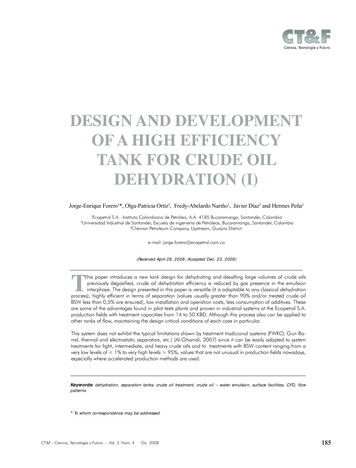
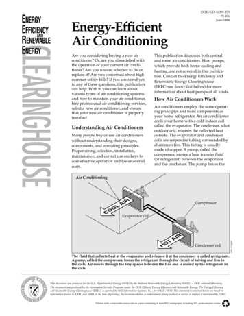
Hamilton Laboratory SolutionsFume Hood TechnologyHow a Fume Hood WorksThe complexities of fume hood operation become apparentwhen the many variables involved in exhausting fumesgenerated in the space are considered.An adequate ”pull” of air, known as face velocity is requiredto move fumes from the fume hood through the ductwork.Face velocity is measured in feet per minute (FPM) at thevertical sash plane. In order to maintain consistent facevelocity, a certain quantity of air, or exhaust volume, isrequired. Exhaust volume is measured in cubic feet per minute(CFM).Sash position also impacts face velocity. The sash is atransparent panel set in the fume hood face.Airflow patterns into the fume hood are influenced by theair foil. Located just beneath the sash, the air foil decreasesturbulence of air entering the fume hood. Some fume hoodsfeature air foils on the left and right sides of the sash as well.SashBafflesAir FoilFume Hood with Air FoilFume Hood Without Air FoilThese diagrams illustrate how an air foil can reduce the turbulence ofair entering a fume hood, thus improving fume hood containment.Dimensions are nominal. Illustrations and specifications are based on the latest product information available at the time of publication.Fume Hoods 0918-34hamiltonlab.com
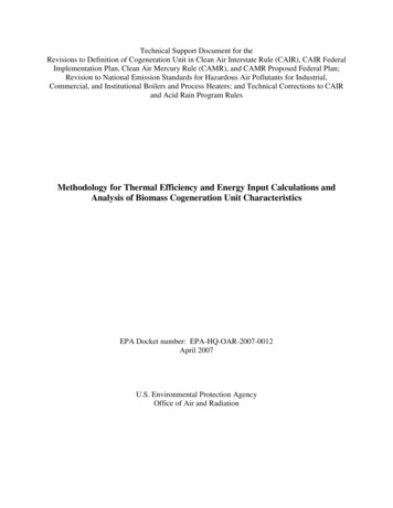
Hamilton Laboratory SolutionsFume Hood TechnologyHow a Fume Hood Works (continued)Located across the inside rear of the fume hood, baffles control airflow patterns through the fume hood. Baffle panels are located in aposition determined to be most effective for the application. A remote adjustment option allows the user to reposition the baffles accordingto characteristics of effluents generated in the fume hood.Remote baffle adjustment located on the outside of the fume hood corner post complies with OSHA Lab Standard recommendations.Baffle PositionsFor lighter-than-air gases and high heatgeneration, maximum airflow is providedat the top of the fume hood. The top slot isadjusted to wide open, center and side slotsremain at normal position, and the bottomslot is reduced.For heavier-than-air gases and fumesgenerated at the work surface, maximum airflow is provided at the bottom of the fumehood, near the work surface. The top slot isclosed, and the center, side and bottom slotsare open.Concept and Pioneer fume hoods onlyhave a fixed baffle for lower face velocityapplications.Sash PositionsSash operating position while work is beingperformed in the fume hood is a maximum 18”opening for vertical rising sashes.Sash setup position is defined as an openinggreater than the operating position for loadingmaterials with which to perform work. Workshould not be performed in the setup position.Dimensions are nominal. Illustrations and specifications are based on the latest product information available at the time of publication.Fume Hoods 0918-35hamiltonlab.com
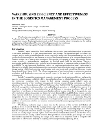
Hamilton Laboratory SolutionsFume Hood TechnologyFume Hood Exhaust SystemsTwo types of fume hood exhaust systems are constant volume (CV) and variable air volume (VAV). Either system can be used withindividual or manifold duct and blower configurations (see page 8). The fume hood exhaust system must be compatible with the room’sHVAC system.The type of fume hood and related exhaust system will depend on the building’s HVAC system, the number of fume hoods in the lab, andany special or unique requirements. Consult with a Hamilton representative, Facilities Manager and/or HVAC contractor.Constant Volume Exhaust SystemsConstant volume fume hoods maintain consistent exhaust volume regardless of sash position. Face velocity varies as the sash is moved.Three types of fume hoods can provide constant volume function: Bypass, Auxiliary Air, and Restricted Bypass.Bypass Fume Hood with Constant Volume Exhaust SystemsIncorporating a bypass, or additional opening for exhaust air whenthe sash is lowered, is one way to keep face velocities within anacceptable range while maintaining a balance between the roomventilating system and fume hood exhaust volume.Constant volume fume hoods are equipped with a bypass locatedabove the sash which opens as the sash is lowered thereby allowingadditional air to enter the fume hood. Hamilton fume hoods alsofeature a lower bypass located below the bottom air foil sill whichcontinuously purges the work surface area.The face velocity will increase as the sash is lowered. The bypassacts as a relief to limit the increase in face velocity. This negatesadverse effects on papers, powders or flames inside the fume hood.A Constant Volume Bypass fume hood shown first with the sash in theoperating position and room air entering from the sash opening, then withthe sash closed and room air entering through the louvered and lowerbypass openings.Auxiliary Air Fume Hood with Constant Volume Exhaust SystemsWhen there is insufficien
Based on the fume hood interior volume, the ANSI Z9.5 minimum air flow is 150-375 air changes per hour with the sash closed. Constant volume operation can be achieved when Restricted Bypass fume hoods are equipped with ”face opening reducing devices” and when the exhaust system is sized to maintain operational exhaust volume and face velocity at the reduced opening. Face opening reducing .