Transcription
BEST PRACTICESVMware NSX for vSphere (NSX-v)and F5 BIG-IP Best Practices Guide
BEST PRACTICESVMware NSX for vSphere (NSX-v) and F5 BIG-IPContentsIntroduction3Topology 1: Parallel to NSX Edge Using VXLAN Overlays withBIG-IP Physical Appliances4Key Components4Implementation Infrastructure5Traffic Management between Data Centers5Create and Deploy DLR17NSX Edge Static Routing Configuration23BIG-IP Appliance Configuration25Validation36Topology 2: Parallel to DLR Using VLANs with BIG-IP PhysicalAppliances38Implementation Infrastructure39Create and Deploy DLR42BIG-IP Appliance Configuration48Validation60Topology 3: One-Arm Connected Using VXLAN Overlays withBIG-IP Virtual Edition62Implementation Infrastructure63NSX Edge Configuration66Create and Deploy DLR72NSX Edge Static Routing Configuration79BIG-IP Appliance Configuration81Provision BIG-IP Network Adapters in vSphere82Provision BIG-IP Networking85Validation105Conclusion1062
BEST PRACTICESVMware NSX for vSphere (NSX-v) and F5 BIG-IPIntroductionThe Software-Defined Data Center (SDDC) is characterized by server virtualization, storagevirtualization, and network virtualization. Server virtualization has already proved the value ofSDDC architectures in reducing costs and complexity of the compute infrastructure. VMwareNSX network virtualization provides the third critical pillar of the SDDC. It extends the samebenefits to the data center network to accelerate network service provisioning, simplifynetwork operations, and improve network economics.By deploying F5 BIG-IP and NSX together, organizations are able to achieve serviceprovisioning automation and agility enabled by the SDDC. This is combined with the richnessof the F5 application delivery services they have come to expect.This guide provides configuration guidance and best practices for the topologies articulated inthe NSX F5 Design Guide to optimize interoperability between the NSX platform and F5 BIG-IPphysical and virtual appliances. It is designed to validate and complement the scenariosdescribed in the NSX F5 Design Guide and is intended for customers who would like to adoptthe SDDC while ensuring compatibility and minimal disruption to their existing BIG-IPenvironment.3
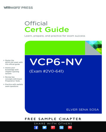
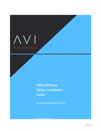
BEST PRACTICESVMware NSX for vSphere (NSX-v) and F5 BIG-IPTopology 1: Parallel to NSX Edge UsingVXLAN Overlays with BIG-IP PhysicalAppliancesFigure 1. BIG-IP appliance parallel to NSX Edge Services GatewayThe first deployment scenario utilizes a topology that creates a second data path forapplication delivery traffic with BIG-IP appliances arranged logically adjacent to the NSXEdge Services Gateway. This allows application specific optimizations and load balancingdecisions to take place before traversing the overlay network. It is also a key enforcementpoint for application specific security policies to be built, from layer 4 through layer 7,outside the flow and policy enforcement for traditional east-west traffic. This design alsoprovides a range of isolated private address space in the transit segment to be used forapplication VIPs and SNATs for inter-tier load balancing.4
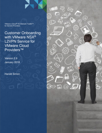
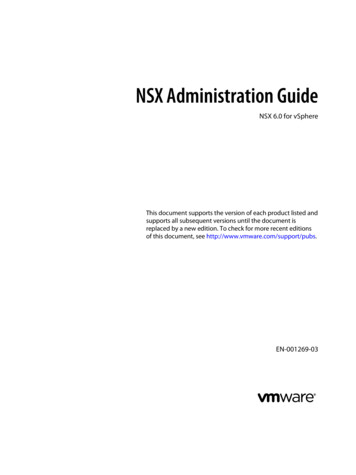
BEST PRACTICESVMware NSX for vSphere (NSX-v) and F5 BIG-IPFigure 2. Leaf/spine physical rack infrastructureThis topology is popular on standard layer 3 physical fabrics as seen in a leaf/spine topologybut is equally applicable to a flat layer 2 infrastructure. The physical placement of the BIG-IPappliances should be in the same infrastructure racks as those reserved for the NSX EdgeServices Gateway deployments.Implementation InfrastructureIn the validation environment, several ESXi clusters are in use. Some of the clusters areNSX-enabled clusters and some are not.For the purposes of explaining and building the validation infrastructure, we will be usingtwo of the clusters listed in Figure 3: the USSJ-55-Management Cluster and the USSJ-55Computer Cluster. While this is a smaller representation of a typical data center deployment,the hardware is segregated in a manner consistent with that shown in Figure 2.Figure 3. vSphere console5
BEST PRACTICESVMware NSX for vSphere (NSX-v) and F5 BIG-IPIn accordance with best practices, edge and compute ESXi hosts are physically andlogically separated from one another. Physical F5 devices are installed in dedicated edgeracks, along with vCenter, NSX manager, and the NSX Edge Services Gateways, whichalso will be installed in the management racks.The virtual machines used as Web (Web), Application (App), and Database (DB) servers willbe running on ESXi hosts in the compute cluster. To better understand data traffic flows forthis deployment scenario topology, examine the VMWare NSX for vSphere (NSX-V) andBIG-IP Design Guide.PrerequisitesReferencing the diagram in Figure 1, the BIG-IP appliance requires connectivity for twophysical interfaces. One interface is used for management of the device and the other isused for all production traffic. The VLAN numbers, the VXLAN segment IDs and the IPaddressing scheme can be tailored to your environment. The physical BIG-IP appliances will need to be installed and connected to the edgerack top-of-rack switches. Each BIG-IP appliance’s management interface will needto be connected to a switchport on a top-of-rack management switch andconfigured with an IP address in the management segment. For this environment, a BIG-IP interface 1.1 will need to be connected to a switchporton the edge rack top-of-rack switch that 802.1Q tags the VLANs used in thisenvironment. In the example, VLANs 20 and 159 are used. Physical network infrastructure switches connected to the ESXi servers and BIG-IPappliance are configured to support 802.1Q tagging and allow the appropriateVLANs. ESXi hosts will need to be configured with the appropriate distributed port groupsand virtual switches.Name802.1Q VLAN IDExternal20dvs VL155 NSXIPPool155TransitNet-1159Table 1. VLAN tags for configuration on distributed virtual switch and physical switches6
BEST PRACTICESVMware NSX for vSphere (NSX-v) and F5 BIG-IPNameTransport ZoneSegment IDControl Plane ble 2. Logical switch configurationNetwork SegmentsTwo types of network segments are utilized in this topology: traditional 802.1Q VLANnetwork segments and VXLAN overlay segments. Within NSX, we created IP Pools thatwill be used by the Web, App, and DB virtual machines.802.1Q VLAN segmentsVLAN 20 External is the VLAN used for external connectivity. The 20.20.20.0/24 IP subnetrange is configured on this VLAN.VLAN 155 dvs VL155 NSXIPPool (not shown) is for management connectivity. The10.105.155.0/24 IP subnet range is configured on this VLANVLAN 159 TransitNet-1 is the VLAN used as the transit VLAN between the BIG-IPappliance and the NSX Edge for application traffic. The 172.16.1.0/24 IP subnet range isconfigured on this VLAN.VXLAN SegmentsThe Web, App, and DB tier virtual machines are all provisioned and connected to VXLANs.VXLAN 7000 Web-Tier-01 is the segment ID used for the blue web connectivity.The 10.0.1.0/24 IP subnet range is configured on this VXLAN.VXLAN 7001 App-Tier-01 is the segment ID used for the yellow app connectivity.The 10.0.2.0/24 IP subnet range is configured on this VXLAN.VXLAN 7002 DB-Tier-01 is the segment ID used for the green DB connectivity.The 10.0.3.0/24 IP subnet range is configured on this VXLAN.VXLAN 7003 TransitNet-2 is the VXLAN segment ID used for the transport zonebetween the DLR and the NSX Edge.7
BEST PRACTICESVMware NSX for vSphere (NSX-v) and F5 BIG-IPNSX Edge Configuration1.In the vSphere Web Client console, begin by navigating to Networking & Security inthe left column. Under Networking and Security, choose NSX Edges and then click thegreen plus symbol ( ).2.Select Edge Services Gateway as the Install Type and provide a name for the device,then click Next.8
BEST PRACTICESVMware NSX for vSphere (NSX-v) and F5 BIG-IP3.Under Settings, select Enable SSH access and provide a username and passwordfor the Edge Services Gateway. Click Next.4.Under Configure deployment, select the Datacenter and Appliance Size appropriatefor your deployment, and check the Deploy NSX Edge checkbox. Then click on thegreen plus symbol ( ) under NSX Edge Appliances.9
BEST PRACTICESVMware NSX for vSphere (NSX-v) and F5 BIG-IP5.Selecting the green plus symbol will display the options in the screenshot below.Choose the appropriate Cluster/resource pool and Datastore (for this example, theUSSJ-55-Management Cluster and the 2240-2-10K datastore). The host selectionis optional. Click OK to complete. This will return you to the configure deploymentscreen shown in step 4. Click Next to continue.6.In the Configure interfaces dialog box, select the green plus symbol to display theAdd NSX Edge Interface dialog box.10
BEST PRACTICESVMware NSX for vSphere (NSX-v) and F5 BIG-IP7.Provide a name and click Select next to the Connected To field.11
BEST PRACTICESVMware NSX for vSphere (NSX-v) and F5 BIG-IP8.For the External network, click on the Distributed Portgroup tab and then selecting thePortgroup used for external access. Click OK.12
BEST PRACTICESVMware NSX for vSphere (NSX-v) and F5 BIG-IP9.Once the network is chosen, select the green plus symbol ( ) under Configure subnetsto add the appropriate IP address and subnet configuration to the interface.13
BEST PRACTICESVMware NSX for vSphere (NSX-v) and F5 BIG-IP10. In the Add Subnet dialog box, enter the appropriate IP address and Subnet prefixlength, and click OK.14
BEST PRACTICESVMware NSX for vSphere (NSX-v) and F5 BIG-IP11. This will bring you back to the Configure interfaces dialog box. For each of the threeinterfaces required for this deployment scenario, configure the appropriate subnetsand switch type, according to the table below.Network NameTypeNetworkInterface IP /Subnet PrefixExternalUplinkDistributed Port Group20.20.20.2/24TransitNet-1UplinkDistributed Port Group17.16.1.1/24TransitNet-2InternalLogical Switch172.16.2.1/24Table 3. NSX Edge network interfaces12. Once the interface settings are completed, the next step is to configure the defaultgateway settings. The default gateway is our data center backbone router with the IPaddress of 20.20.20.1 on External vNIC that we configured under the interface settings.Use the default MTU parameter unless the network is using an MTU of a different size,such as jumbo frames. (Configuring a non-standard MTU that is inconsistent can leadto unnecessary fragmentation of packets or black-holing of some traffic.) Click Next tocontinue.15
BEST PRACTICESVMware NSX for vSphere (NSX-v) and F5 BIG-IP13. HA settings can be left as default. Check Configure firewall default policy and checkAccept for the Default Traffic Policy.14. Select Finish to complete the deployment of the NSX Edge.16
BEST PRACTICESVMware NSX for vSphere (NSX-v) and F5 BIG-IPCreate and Deploy DLRWithin VMWare NSX, the Distributed Logical Router (DLR) provides an optimized way ofhandling east-west traffic within the data center. East-west traffic consists ofcommunication between virtual machines or other resources on different subnets within adata center. As east-west traffic demand increases within the data center, the distributedarchitecture allows for optimized routing between VXLAN segments.(Note that DLR and LDR—Logical (Distributed) Router—are used synonymously byVMware.)1.Return to the vSphere Web Client console and choose Networking & Security in theleft column. Under Networking and Security, choose NSX Edges and then click thegreen plus symbol ( ).2.Select Logical (Distributed) Router as the Install Type and provide a name for thedevice, then click Next.17
BEST PRACTICESVMware NSX for vSphere (NSX-v) and F5 BIG-IP3.Under Settings, check Enable SSH access and provide a username and password forthe Edge Services Gateway. Select Next.4.Selecting the green plus symbol ( ) in the Configure Deployment section will display theoptions in the figure below. Choose the appropriate Cluster/resource pool andDatastore (for this example, the NSX Computer Cluster and the 2240-2-10K datastore).The Host is optional. Click OK to complete and Next to continue. This will return you tothe screen shown in step 2.18
BEST PRACTICESVMware NSX for vSphere (NSX-v) and F5 BIG-IP5.Select Configure Interfaces, and then click Select to the right of the Connected Totext box.a.In this case, the management interface should be connected to a distributed portgroup that is connected to the shared management VLAN.19
BEST PRACTICESVMware NSX for vSphere (NSX-v) and F5 BIG-IPb.Click the green plus symbol ( ) to specify a fixed IP address and Subnet prefixlength in the management network. Click OK to complete.6.For each of the four interfaces required for this topology, configure the appropriatesubnets and switch type according to the table below. Select the green plus symbol ( )under Configure Interfaces of this NSX Edge to bring up the Add Interface dialog box.20
BEST PRACTICESVMware NSX for vSphere (NSX-v) and F5 BIG-IPNetwork NameConnected ToTypeNetworkInterface l Switch172.16.2.2/24WebTierWebTierInternalLogical Switch10.0.1.1/24AppTierAppTierInternalLogical Switch10.0.2.1/24DBTierDBTierInternalLogical Switch10.0.3.1/24Table 4. NSX distributed logical router network interfacesThe DLR interface configuration, once completed, should resemble the dialog box below.Click Next to continue.7.With the interface settings complete, the next step is to configure the default gatewaysettings. The default gateway for the DLR is the data center core router that weconfigured in the previous section across the transit segment TransitNet2.For the vNIC, select TransitNet2 and provide the Gateway IP address of the NSX Edge.In this example, it is 172.16.2.1. Click Next to proceed.21
BEST PRACTICESVMware NSX for vSphere (NSX-v) and F5 BIG-IP8.Click Ready to complete to review your configuration and then click Finish to deploythe DLR. Depending on the number of ESXi hosts, it may take some time for the DLRdeployment to complete.9.Once complete, the vSphere NSX Edges configuration should resemble the imagebelow.22
BEST PRACTICESVMware NSX for vSphere (NSX-v) and F5 BIG-IPNSX Edge Static Routing ConfigurationFor this deployment scenario, static routing is configured to allow the NSX Edge to forwardpackets into the different tiered networks via the DLR. The default gateway configuration onboth the NSX Edge and the DLR ensures packets find their way out to external networks.This configuration is also required to ensure that traffic coming from the external networksfinds its way in.1.Double-click on the NSX Edge you configured in the first section.2.The configuration screen below should now be displayed. Click on the Manage taband then select the Routing sub-tab. In the left-hand column, click Static Routes, andthen click the green plus symbol ( ) to bring up the Add Static Route configurationdialog box.23
BEST PRACTICESVMware NSX for vSphere (NSX-v) and F5 BIG-IP1.Provide an internal summary route that points the NSX Edge to the TransitNet-2 IPAddress of the DLR interface. In this case, a summary of 10.0.0.0/16 is pointedinternally to the DLR IP address of 172.16.2.2. Click OK.2.Click Publish Changes to push the updated routing information to the NSX Edge.24
BEST PRACTICESVMware NSX for vSphere (NSX-v) and F5 BIG-IPBIG-IP Appliance ConfigurationThe validation of this topology is currently configured on a single device. The base networkconfiguration consists of configuring the VLANs and assigning them to an interface as wellas creating the appropriate self IP addresses for each of the network segments. Forproduction deployments, F5 recommends that two BIG-IP devices be configured in an HAconfiguration.Prerequisites The BIG-IP appliance is configured with a management IP address in the propersubnet. Licenses have been applied and activated. Appropriate provisioning of resources is complete. Base configuration of services DNS, NTP, SYSLOG are configured. BIG-IP Interface 1.1 is physically wired to a switch configured to support 802.1Qtagging of traffic on VLANs 20 and 159.For info on how to perform these installation and basic setup steps, refer tohttp://support.f5.com and consult the appropriate implementation guide for your versionand device.Create VLANs1.From the Main tab of the BIG-IP Configuration Utility navigation pane, expandNetwork and select VLANs.2.In the upper right corner, click Create.25
BEST PRACTICESVMware NSX for vSphere (NSX-v) and F5 BIG-IP3.Under General Properties, enter a unique name for the VLAN. In this example, weused External.4.In the Tag field, enter the External VLAN ID of 20.5.Under Resources, for Interface, select 1.1.6.Select Tagged and then click the Add button below it.7.Select Repeat to proceed with creating the transit network.8.Under General Properties, enter a unique name for the VLAN. In this example, weused TransitNet1.9.For the Tag, enter the TransitNet-1 VLAN ID of 159.10. Under Resources, select the Interface 1.1.11. Select Tagged and click the Add button below it.12. Select Finished to complete the VLAN creation.26
BEST PRACTICESVMware NSX for vSphere (NSX-v) and F5 BIG-IPConfigure Self IP AddressesSelf IP addresses are logical interfaces that allow the BIG-IP to participate in the networksfor which they are configured. They also are useful for functions such as SNAT to ensuresymmetric traffic patterns.1.On the Main tab of the BIG-IP navigation pane, click Network and then click Self IPs.2.In the upper right corner of the screen, click the Create button.3.Type a unique name in the Name box. In this example, we used Extself IP.4.In the IP address box, type the IP address you want to assign to a VLAN. For theExternal network, use 20.20.20.10.5.Provide the appropriate subnet mask in the Netmask box. In this example, we used255.255.255.0.6.For the VLAN/Tunnel, select External from the dropdown box.7.Use the default settings for Port Lockdown and Traffic Group.8.Click the Repeat button to continue.27
BEST PRACTICESVMware NSX for vSphere (NSX-v) and F5 BIG-IP9.Complete the configuration for the TransitNetSelf self IP using the following settings:a.Name: TransitNetSelfb.IP Address: 172.16.1.2c.Netmask: 255.255.255.0d.VLAN/Tunnel: TransitNet110. Click Finished to validate the completed self IP configuration.28
BEST PRACTICESVMware NSX for vSphere (NSX-v) and F5 BIG-IPConfigure Static RoutesTo ensure the BIG-IP can properly forward requests to the application servers within theoverlay network and also communicate with all external networks, static routing is used toprovide two discreet paths for traffic. The External VLAN will be used for web tierapplication traffic VIPs; TransitNet-1 will be used for application tier VIPs as well as thesource IP for SNAT traffic.1.From the Main tab of the BIG-IP Configuration Utility navigation pane, expandNetwork and select Routes.2.For the Name, use the keyword default.3.The default route for both Destination and Netmask is 0.0.0.0.4.The Gateway Address is the address of the core router, 20.20.20.1.5.Click Repeat to complete and add the second route.6.For the network route pointing internally to the application servers, use the NameServerRoutes.7.The Destination and Netmask for ServerRoutes is 10.0.0.0 and 255.255.0.0respectively.29
BEST PRACTICESVMware NSX for vSphere (NSX-v) and F5 BIG-IP8.The Gateway Address is the address of the NSX Edge Service Gateway on the transitsegment TransitNet1: 172.16.1.1.9.Click Finished to continue.10. The completed routing configuration should resemble the configuration below.Application ConfigurationApplication configuration typically consists of a base configuration of pool members thatare contained within the pool object. The virtual server references the pool to make a loadbalancing decision among the available pool members. Additional application deliveryfunctionality such as SSL termination, more flexible load balancing algorithm selection,30
BEST PRACTICESVMware NSX for vSphere (NSX-v) and F5 BIG-IPand layer 7 data plane programmability via iRules can be leveraged but are outside thescope of this validation.Create application poolsIn the following examples, we are creating the most basic of pools for our web and appservers to show the minimum configuration that’s required in order for the F5 appliance toload balance the two tiers (web and app). The F5 device will not be load balancing the DBtier traffic, so we are not creating a pool of the DB servers.1.On the Main tab, click Local Traffic and then click Pools to display the Pool List screen.2.In the upper right corner of the screen, click the Create button.3.In the Name field, type a unique name for the web pool. For this validation, we usedWebServerPool.4.In the Health Monitors section, select an appropriate monitor for your application. Inthis case, we chose a gateway icmp monitor to ensure server health, but much morein-depth health monitoring is available to determine application availability.5.Under Resources, select a Load Balancing Method. For basic load balancing in thisvalidation, Round Robin was used.6.Under Resources, use the New Members setting to add the IP address and port ofthe web servers (refer to Table 5 below). Click the Add button for each pool member.7.Click Repeat to continue and enter the application tier information.Name (Optional)AddressService Portweb-0110.0.1.1180 (HTTP)web-0210.0.1.1280 (HTTP)Table 5. BIG-IP web tier pool members31
BEST PRACTICESVMware NSX for vSphere (NSX-v) and F5 BIG-IP8.In the Name field, type a unique name for the web pool. For this validationAppServerPool was used.9.In the Health Monitors section select an appropriate monitor for your application. Inthis case, we are choosing a gateway icmp monitor to ensure server health, but muchmore in-depth health monitoring is available to determine application availability.10. In the Resources section of the screen select a Load Balancing Method. For basicload balancing in this validation, Round Robin was used.11. In the Resources section of the screen, use the New Members setting to add the IPaddress and port of the web servers (refer to Table 6). Select the Add button for eachpool member.12. Click Finished to complete the pool creation.32
BEST PRACTICESVMware NSX for vSphere (NSX-v) and F5 BIG-IPName (Optional)AddressService PortApp-0110.0.2.1180 (HTTP)App-0210.0.2.1280 (HTTP)Table 6. BIG-IP application tier pool membersThe completed configuration for the web and application tier pools should look similar to theimage below. Note that the green circles demonstrate that the health monitor, in this case,ICMP, is able to successfully monitor the servers in the overlay networks.33
BEST PRACTICESVMware NSX for vSphere (NSX-v) and F5 BIG-IPCreate application virtual serverIn creating a virtual server, you specify a destination IP address and service port on whichthe BIG-IP appliance is listening for application traffic to be load balanced to the appropriateapplication pool members. In this validation, we have two virtual servers (VIPs) to create:one for the web tier, which will be available to the external network on the 20.20.20.0/24segment, and the other for the application tier, available on the TransitNet-1 segment.1.On the Main tab, select Local Traffic and then click Pools. The Pool List screen isdisplayed.2.In the upper right corner of the screen, click the Create button.3.In the Name field, provide a unique name for the web application. In this case, we usedWeb-Vip.4.In the Destination Address field, enter 20.20.20.5.5.For Service Port use the standard HTTP port 80.6.In the Configuration section, select Auto Map for the Source Address Translation.7.Under Resources, select the WebServerPool from the Default Pool dropdown box.8.Click Repeat to continue to configure the application tier virtual server.34
BEST PRACTICESVMware NSX for vSphere (NSX-v) and F5 BIG-IP35
BEST PRACTICESVMware NSX for vSphere (NSX-v) and F5 BIG-IP1.2.In the upper right corner of the screen, click the Create button.In the Name field, provide a unique name for the web application. In this case, we usedApp-Vip.3.In the Destination Address field, enter the IP address 10.0.1.5.4.For Service Port, use the standard HTTP port 80.5.In the Configuration section, select Auto Map for the Source Address Translation field.6.Under Resources, select AppServerPool from the dropdown box.7.Again, click Finished to continue to configure the application tier virtual server.The virtual server list ought to look similar to the one shown below. The green status iconsindicate that all systems are go with the validation application. The virtual servers and theassociated pools are reachable and healthy.ValidationThe web tier virtual server should now be available and accepting application traffic on port80 (HTTP).On the Main tab, expand Local Traffic and then click Network Map to display the overallhealth of the applications and their associated resources.36
BEST PRACTICESVMware NSX for vSphere (NSX-v) and F5 BIG-IPAny web browser can be used to test by typing http://20.20.20.5 to send a request to thevirtual server. A simple Apache web server can be installed on the web tier to validate.This concludes the validation of the Adjacent to NSX Edge Using VXLAN Overlays withBIG-IP Physical Appliances deployment scenario.37
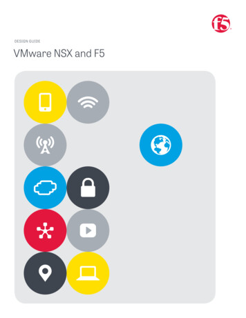
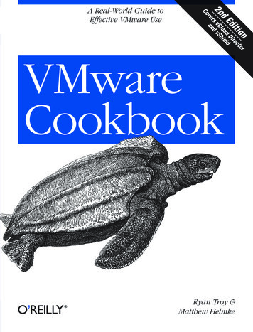
BEST PRACTICESVMware NSX for vSphere (NSX-v) and F5 BIG-IPTopology 2: Parallel to DLR UsingVLANs with BIG-IP PhysicalAppliancesFigure 4. BIG-IP appliances parallel to DLRThe second deployment scenario also utilizes a topology with a second data path forapplication delivery traffic. BIG-IP appliances are arranged logically parallel to theDistributed Logical Router (DLR). There is no requirement in this scenario for an NSX EdgeServices Gateway.The BIG-IP appliance has 802.1Q tagged interfaces directly into the web and applicationtiers. This allows application-specific optimizations and load balancing decisions to takeplace, and the BIG-IP appliance will let the layer 2 network determine the optimal pathbetween the BIG-IP appliance and the application servers. It is also a key enforcementpoint for application-specific security policies to be built from layer 4 through layer 7 outsidethe flow and policy enforcement for traditional east-west traffic. Since the BIG-IP applianceis directly connected to the application networks, address space for application VIPs andSNATs for inter-tier load balancing can be utilized from those individual networks and do notneed to traverse a transit network.38
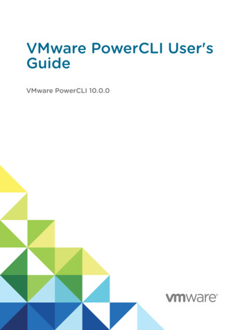
BEST PRACTICESVMware NSX for vSphere (NSX-v) and F5 BIG-IPFigure 5. Traditional layer 2 topology with BIG-IP in distribution layerThe physical topology in this deployment scenario connects the BIG-IP appliance in thetraditional distribution tier to provide an optimal layer 2 path for application traffic. The DLRinstances provide an optimal east-west path between tiers and to external networks.Implementation InfrastructureIn the validation environment, the same ESXi clusters are in use.For the purposes of explaining and building the validation infrastructure, we will be usingtwo of the clusters listed in Figure 6: USSJ-55-Management Cluster and the USSJ-55Compute Cluster. While this is a smaller representation of a data center deployment, thehardware is segregated in a manner consistent with that shown in Figure 5.Figure 6. vSphere console39
BEST PRACTICESVMware NSX for vSphere (NSX-v) and F5 BIG-IPIn accordance with best practices, management and compute ESXi hosts are physicallyand logically separated from one another. Physical BIG-IP devices are installed indistribution racks, and vCenter and NSX manager will be installed in the management racks.The virtual machines used as Web (web), Application (app), and Database (DB) servers willbe running on ESXi hosts in the compute cluster. To better understand data traffic flows forthis deployment scenario topology, examine the VMWare NSX for vSphere (NSX-V) andBIG-IP Design Guide.PrerequisitesReferencing the diagram in Figure 4, the BIG-IP appliance requires connectivity for twophysical interfaces. One interface is used for management of the device and the other isused for all production traffic. The VLAN numbers, and the IP addressing scheme can betailored to your environment. The physical BIG-IP appliances will need to be installed and connected to thedistribution switches. Each BIG-IP appliance’s management interface will need to beconnected to a switchport on a top-of-rack management switch that has themanagement VLAN extended to it, and configured with an IP address in themanagement segment. For this environment, a BIG-IP interface 1.1 will need to be connected to a switchporton the distribution switch that 802.1Q tags the VLANs used in this environment. Inthe example, VLANs 20, 160, 161, and 162 are used. Physical network infrastructure switches connected to the ESXi servers areconfigured to support 802.1Q tagging and allow the appropriate VLANs. ESXi hosts will need to be configured with the appropriate distributed port groupsand virtual switches.Name802.1Q VLAN IDExternal20dvs VL155 162Table 7. VLAN tags for configuration on distributed virtual switch and physical switches40
BEST PRACTICESVMware NSX for vSphere (NSX-v) and F5 BIG-IPNetwork SegmentsTwo types of network segments are utilized in this topology: traditional 802.1Q VLANnetwork segments and VXLAN overlay segments. Within NSX, we created IP pools that willbe used by the Web, App, and DB virtual machines.802.1Q VLAN segmentsVLAN 20 External is the VLAN used for external connectivity. The 20.20.20.0/24 IP subnetrange is configured on this VLAN.VLAN 155 dv
BIG-IP Physical Appliances 4 Key Components 4 Implementation Infrastructure 5 . VMware NSX for vSphere NSX-v and BIG-IP 8 NSX Edge Configuration 1. In the vSphere Web Client console, begin by navigating to Networking & Security in the left column. Under Networking and Security, choose NSX Edges and then click the