Transcription
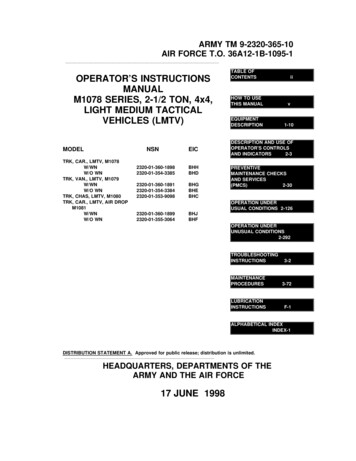
ARMY TM 9-2320-365-10AIR FORCE T.O. 36A12-1B-1095-1OPERATOR’S INSTRUCTIONSMANUALM1078 SERIES, 2-1/2 TON, 4x4,LIGHT MEDIUM TACTICALVEHICLES (LMTV)MODELNSNTRK, CAR., LMTV, M1078W/WNW/O WNTRK, VAN., LMTV, M1079W/WNW/O WNTRK, CHAS, LMTV, M1080TRK, CAR., LMTV, AIR DROPM1081W/WNW/O TABLE OFCONTENTSiiHOW TO USETHIS MANUALvEQUIPMENTDESCRIPTION1-10DESCRIPTION AND USE OFOPERATOR’S CONTROLSAND INDICATORS2-3PREVENTIVEMAINTENANCE CHECKSAND SERVICES(PMCS)2-30OPERATION UNDERUSUAL CONDITIONS ON UNDERUNUSUAL ABETICAL INDEXINDEX-1DISTRIBUTION STATEMENT A. Approved for public release; distribution is unlimited.HEADQUARTERS, DEPARTMENTS OF THEARMY AND THE AIR FORCE17 JUNE 1998
ARMY TM 9-2320-365-10AIR FORCE T.O. 36A12-1B-1095-1TECHNICAL MANUALNO. 9-2320-365-10HEADQUARTERSDEPARTMENTS OF THE ARMYAND THE AIR FORCETECHNICAL ORDERNO. 36A12-1B-1095-1Washington, D.C., 17 June 1998Operator’s Instructions ManualM1078 SERIES, 2-1/2 TON, 4x4LIGHT MEDIUM TACTICAL VEHICLES (LMTV)MODELNSNEICTRK, CAR., LMTV, M1078W/WNW/O WN2320-01-360-18982320-01-354-3385BHHBHDTRK, VAN., LMTV, M1079W/WNW/O WN2320-01-360-18912320-01-354-3384BHGBHETRK, CHAS, LMTV, M10802320-01-353-9098BHCTRK, CAR., LMTV, AIR DROP, M1081W/WNW/O WN2320-01-360-18992320-01-355-3064BHJBHFREPORTING ERRORS AND RECOMMENDING IMPROVEMENTSYou can help improve this publication. If you find any mistakes or if you know of away to improve the procedures, please let us know. Submit your DA Form 2028(Recommended Changes to Equipment Technical Publications), through theInternet, on the Army Electronic Product Support (AEPS) website. The Internetaddress is http://aeps.ria.army.mil. If you need a password, scroll down and clickon "ACCESS REQUEST FORM". The DA Form 2028 is located in the ONLINEFORMS PROCESSING section of the AEPS. Fill out the form and click onSUBMIT. Using this form on the AEPS will enable us to respond quicker to yourcomments and better manage the DA Form 2028 program. You may also mail, faxor Email your letter or DA Form 2028 direct to: AMSTA-LC-CI/TECH PUBS,TACOM-RI, 1 Rock Island Arsenal, Rock Island, IL 61299-7630. The email addressis TACOM-TECH-PUBS@ria.army.mil. The fax number is DSN 793-0726 orCommercial (309) 782-0726.DISTRIBUTION STATEMENT A. Approved for public release; distribution is unlimited.Change 1i
TM 9-2320-365-10TABLE OF CONTENTSPageHOW TO USE THIS MANUAL. vCHAPTER 1. INTRODUCTION . . . . . . . . . . . . . . . . . . . . . . . . . . . . . . . . . . . . . . 1-1Section I.General Information . . . . . . . . . . . . . . . . . . . . . . . . . . . . . 1-1Section II. Equipment DescriptionSection III. . . . . . . . . . . . . . . . . . . . . . . . . 1-10Principles of Operation . . . . . . . . . . . . . . . . . . . . . . . . . . 1-31CHAPTER 2. OPERATING INSTRUCTIONS . . . . . . . . . . . . . . . . . . . . . . . . . . . . 2-1Section I.Description and Use of Operator’s Controls and . . . . . . . . 2-3IndicatorsSection II.Preventive Maintenance Checks and Service . . . . . . . . . . 2-30Section III.Operation Under Usual Conditions . . . . . . . . . . . . . . . . 2-126Section IV.Operation Under Unusual Conditions . . . . . . . . . . . . . 2-292CHAPTER 3. MAINTENANCE INSTRUCTIONS . . . . . . . . . . . . . . . . . . . . . . . . . 3-1Section I.Lubrication Instructions . . . . . . . . . . . . . . . . . . . . . . . . . . 3-1Section II.Troubleshooting Instructions . . . . . . . . . . . . . . . . . . . . . . 3-2Section III.Maintenance Procedures . . . . . . . . . . . . . . . . . . . . . . . . 3-72APPENDIX A. REFERENCES . . . . . . . . . . . . . . . . . . . . . . . . . . . . . . . . . . . . . A-1APPENDIX B. COMPONENTS OF END ITEM (COEI) AND BASICISSUE ITEMS (BII) . . . . . . . . . . . . . . . . . . . . . . . . . . . . . . . . . . B-1APPENDIX C. ADDITIONAL AUTHORIZATION LIST (AAL) . . . . . . . . . . . . . . . C-1ii
TM 9-2320-365-10PageAPPENDIX D. EXPENDABLE AND DURABLE ITEMS LIST . . . . . . . . . . . . . . . D-1APPENDIX E. STOWAGE AND DECAL/DATA PLATE GUIDE . . . . . . . . . . . . . E-1APPENDIX F. LUBRICATION INSTRUCTIONSALPHABETICAL (SUBJECT) INDEX. . . . . . . . . . . . . . . . . . . . . . . F-1. . . . . . . . . . . . . . . . . . . . . . . . . . . INDEX-1LIST OF 92-102-112-122-132-14TitleM1078 Truck, Cargo: 2 1/2-Ton, 4x4, Dropside . . . . . . . . . . . . . .M1079 Truck, Van: 2 1/2-Ton, 4x4 . . . . . . . . . . . . . . . . . . . . . . .M1080 Truck, Chassis: 2 1/2-Ton, 4x4 . . . . . . . . . . . . . . . . . . . .M1081 Truck, Cargo: 2 1/2-Ton, 4x4, Dropside, Air Drop . . . . . . .Common Vehicle Components Location . . . . . . . . . . . . . . . . . . .M1078 and M1081 Cargo Vehicles Components Location . . . . . .M1081 Air Drop Cargo Vehicles Components Location . . . . . . . .M1079 Van Components Location . . . . . . . . . . . . . . . . . . . . . . .Powertrain . . . . . . . . . . . . . . . . . . . . . . . . . . . . . . . . . . . . . . . .Engine Air Intake System . . . . . . . . . . . . . . . . . . . . . . . . . . . . . .Fuel System . . . . . . . . . . . . . . . . . . . . . . . . . . . . . . . . . . . . . . .Cooling System . . . . . . . . . . . . . . . . . . . . . . . . . . . . . . . . . . . . .Electrical System . . . . . . . . . . . . . . . . . . . . . . . . . . . . . . . . . . . .Brake System . . . . . . . . . . . . . . . . . . . . . . . . . . . . . . . . . . . . . .11K Self-Recovery Winch (SRW) . . . . . . . . . . . . . . . . . . . . . . . .Air System . . . . . . . . . . . . . . . . . . . . . . . . . . . . . . . . . . . . . . . .Instrument Panel Controls and Indicators . . . . . . . . . . . . . . . . . .Lighted Indicator Display . . . . . . . . . . . . . . . . . . . . . . . . . . . . . .Main Light Switch . . . . . . . . . . . . . . . . . . . . . . . . . . . . . . . . . . .WTEC II Transmission ECU Pushbutton Shift Selector (TEPSS) . .WTEC III Transmission Pushbutton Shift Selector (TPSS) . . . . . .Auxiliary Panel Controls and Indicators . . . . . . . . . . . . . . . . . . . .Air System Controls . . . . . . . . . . . . . . . . . . . . . . . . . . . . . . . . . .Heater/Defrost Controls . . . . . . . . . . . . . . . . . . . . . . . . . . . . . . .Central Tire Inflation System (CTIS) Electronic Control Unit (ECU)Controls and Indicators . . . . . . . . . . . . . . . . . . . . . . . . . . . . . . .Steering Column Controls . . . . . . . . . . . . . . . . . . . . . . . . . . . . .Floor-Mounted Controls . . . . . . . . . . . . . . . . . . . . . . . . . . . . . . .Door-Mounted Controls . . . . . . . . . . . . . . . . . . . . . . . . . . . . . . .Driver’s Seat Controls . . . . . . . . . . . . . . . . . . . . . . . . . . . . . . . .Right Passenger Seat Controls . . . . . . . . . . . . . . . . . . . . . . . . .Page. 1-3. 1-4. 1-5. 9. 2-3. 20iii
TM 9-2320-365-10LIST OF ILLUSTRATIONS tlePassenger Side Exterior Controls . . . . . . . . . . . . . . . . . . . . .Hydraulic Manifold Controls . . . . . . . . . . . . . . . . . . . . . . . . .Driver’s Side Exterior Controls and Indicators . . . . . . . . . . . .Troop Transport Alarm Switch . . . . . . . . . . . . . . . . . . . . . . .Light Material Handling Crane (LMHC) Controls and IndicatorsDeletedDeletedVan Interior Controls . . . . . . . . . . . . . . . . . . . . . . . . . . . . . .Van Exterior Controls . . . . . . . . . . . . . . . . . . . . . . . . . . . . .Page.2-212-222-232-242-25. . . . . . . . . 2-27. . . . . . . . . 2-29LIST OF 62-72-82-93-13-23-33-4ivTitleDifferences Between Models . . . . . . . . . . . . . . . . . . . . . . . . . . . . .Vehicle Dimensions . . . . . . . . . . . . . . . . . . . . . . . . . . . . . . . . . . . .Vehicle Weights and Payloads . . . . . . . . . . . . . . . . . . . . . . . . . . . .Vehicle Performance Data . . . . . . . . . . . . . . . . . . . . . . . . . . . . . . .Fluid Capacities . . . . . . . . . . . . . . . . . . . . . . . . . . . . . . . . . . . . . .System Data . . . . . . . . . . . . . . . . . . . . . . . . . . . . . . . . . . . . . . . . .Vehicle Classification . . . . . . . . . . . . . . . . . . . . . . . . . . . . . . . . . . .Preventive Maintenance Checks and Services(All Models) . . . . . . . . . . . . . . . . . . . . . . . . . . . . . . . . . . . . . . . . .Preventive Maintenance Checks and Services(M1078 and M1081) . . . . . . . . . . . . . . . . . . . . . . . . . . . . . . . . . . .Preventive Maintenance Checks and Services(M1081) . . . . . . . . . . . . . . . . . . . . . . . . . . . . . . . . . . . . . . . . . . . .Preventive Maintenance Checks and Services(M1079) . . . . . . . . . . . . . . . . . . . . . . . . . . . . . . . . . . . . . . . . . . . .Central Tire Inflation System (CTIS) Tire Pressures and RestrictionsCapacity Chart for Light Material Handling Crane (LMHC) . . . . . . . .Cargo Bed Side Panel Stowage Information . . . . . . . . . . . . . . . . . .11K Self-Recovery Winch (SRW) Pull Capacity . . . . . . . . . . . . . . . .DeletedMalfunction Index . . . . . . . . . . . . . . . . . . . . . . . . . . . . . . . . . . . . .Troubleshooting . . . . . . . . . . . . . . . . . . . . . . . . . . . . . . . . . . . . . .Cold Tire Inflation Pressures and Restrictions . . . . . . . . . . . . . . . . .General Cleaning Instructions . . . . . . . . . . . . . . . . . . . . . . . . . . . .Change 1Page.1-211-221-231-231-241-241-30. . . . 2-34. . . . 2-94. . . 2-111.2-1182-1712-1762-2132-340. 3-23-133-873-94
TM 9-2320-365-10HOW TO USE THIS MANUALOVERVIEWThis Technical Manual (TM) is provided to help you operate and maintain the LightMedium Tactical Vehicles (LMTV). It is divided into the following major sections in orderof appearance: FRONT COVER INDEX. The front cover index contains a list ofthe most important topics contained in the manual. It features ablack box at the right edge of the cover which corresponds witha black box on the page containing the topic. The topics listed onthe front cover are highlighted in the table of contents with a box. WARNING SUMMARY. Provides a summary of the warnings thatappear throughout the manual. Read all WARNINGS andCAUTIONS before performing any operation, troubleshooting ormaintenance procedures. TABLE OF CONTENTS.Lists the Chapters, Sections,Appendixes, and alphabetical Index with Page Number in orderof appearance. CHAPTER 1, INTRODUCTION.provides equipment data. CHAPTER 2, OPERATING INSTRUCTIONS.Describesoperator’s controls and indicators, preventive maintenance, andoperating instructions. CHAPTER 3, MAINTENANCE INSTRUCTIONS.Providesinstructions for Troubleshooting and operator maintenance. APPENDIX A, REFERENCES. Lists publications used with theLMTV and reference publications which contain informationregarding the equipment. APPENDIX B, COMPONENTS OF END ITEM (COEI) ANDBASIC ISSUE ITEMS (BII) LISTS. Lists and illustrates COEI andBII items issued with the LMTV. APPENDIX C, ADDITIONAL AUTHORIZATION LIST (AAL).Lists additional items you are authorized for support of the LMTV. APPENDIX D, EXPENDABLE AND DURABLE ITEMS LIST.Lists expendable and durable Items used in the performance ofmaintenance procedures.Describes the LMTV andv
TM 9-2320-365-10 APPENDIX E, STOWAGE AND DECAL/DATA PLATE GUIDE.Shows the location of signs and details the location of COEI, BII,and AAL items. APPENDIX F, LUBRICATION INSTRUCTIONS. Gives operatorlubrication instructions and the time interval at which lubrication isconducted. Lubrication points are also illustrated. SUBJECT INDEX. Lists important subjects contained in thisVolume in alphabetical order, and gives the paragraph numberwhere they are located.FINDING INFORMATIONThere are several ways to find the information you need in this manual. They are asfollows: TABLE OF CONTENTS. Lists Chapters, Sections, Appendixes,and Indexes with Page Numbers in order of appearance. CHAPTER INDEXES. List Paragraphs contained in the individualChapters with Paragraph and Page Numbers in order ofappearance. MALFUNCTION INDEX. Lists malfunctions contained in theTroubleshooting Table with Page Numbers in order ofappearance. ALPHABETICAL (SUBJECT) INDEX. Lists all important topicswith Paragraph Numbers in alphabetical order.TROUBLESHOOTINGTroubleshooting is contained in Chapter 3. When you have a problem with the operationof your equipment, look at Table 3-1, Malfunction Index on Page 3-2. Find the malfunctionin the Index. Turn to the Page Number listed for the malfunction in Table 3-2,Troubleshooting. Perform the Steps required to correct the malfunction. If you can notfind the malfunction, or the malfunction is not corrected, notify Unit Maintenance.vi
TM 9-2320-365-10OPERATION AND MAINTENANCE OPERATION. Before you operate the LMTV, familiarize yourselfwith the controls and indicators (Chapter 2, Section I). Performyour BEFORE preventive maintenance (Chapter 2, Section II).Read the operating instructions contained in Chapter 2, SectionsIII and IV. Always follow the WARNINGS and CAUTIONS.During operation, perform your DURING preventive maintenance,and after operation perform your AFTER preventive maintenance(Chapter 2, Section II). MAINTENANCE. When you perform maintenance, look over theentire procedure before starting. Make sure you have thenecessary tools and materials at hand.Always observeWARNINGS and CAUTIONS.vii/(viii Blank)
TM 9-2320-365-10CHAPTER 1INTRODUCTIONSection I. GENERAL INFORMATION . . . . . . . . . . . . . . . . . . . . . . . . . . .1-1. SCOPE . . . . . . . . . . . . . . . . . . . . . . . . . . . . . . . . . . . . . . . . . . . .1-2. MAINTENANCE FORMS AND PROCEDURES . . . . . . . . . . . . . . .1-3. CORROSION PREVENTION AND CONTROL (CPC) . . . . . . . . . . .1-4. DESTRUCTION OF ARMY MATERIEL TO PREVENT ENEMY USE1-5. REPORTING EQUIPMENT IMPROVEMENT RECOMMENDATIONS1-6. WARRANTY INFORMATION . . . . . . . . . . . . . . . . . . . . . . . . . . . .1-7. NOMENCLATURE CROSS-REFERENCE LIST . . . . . . . . . . . . . . .1-8. LIST OF ABBREVIATIONS . . . . . . . . . . . . . . . . . . . . . . . . . . . . . .1-9. GLOSSARY . . . . . . . . . . . . . . . . . . . . . . . . . . . . . . . . . . . . . . . . . . . . . 1-1. . . . . 1-1. . . . . 1-7. . . . . 1-7. . . . . 1-7(EIR) 1-8. . . . . 1-8. . . . . 1-8. . . . . 1-8. . . . 1-10Section II. EQUIPMENT DESCRIPTION . . . . . . . . . . . . . . . . . . . . . . . . . . .1-10. EQUIPMENT CHARACTERISTICS, CAPABILITIES, AND FEATURES1-11. LOCATION AND DESCRIPTION OF MAJOR COMPONENTS . . . . .1-12. DIFFERENCES BETWEEN MODELS . . . . . . . . . . . . . . . . . . . . . . .1-13. EQUIPMENT DATA . . . . . . . . . . . . . . . . . . . . . . . . . . . . . . . . . . . I. PRINCIPLES OF OPERATION . . .POWERTRAIN . . . . . . . . . . . . . . . . . .ENGINE AIR INTAKE SYSTEM . . . . . .FUEL SYSTEM . . . . . . . . . . . . . . . . .COOLING SYSTEM . . . . . . . . . . . . . .ELECTRICAL SYSTEM . . . . . . . . . . .BRAKE SYSTEM . . . . . . . . . . . . . . . .11K SELF-RECOVERY WINCH (SRW)AIR SYSTEM . . . . . . . . . . . . . . . . . . 1-461-49Section I. GENERAL INFORMATION1-1. SCOPEThis chapter provides general information, equipment description, and principles ofoperation for the M1078 series Light Medium Tactical Vehicle (LMTV). The LMTV willherein be referred to as the vehicle.a. Type of Manual. This manual provides instructions for operation and Operatormaintenance of the vehicle.b. Name and Model. The vehicle model numbers and names are listed Cargo: 2 1/2-Ton, 4x4, Dropside (Figure 1-1).Van: 2 1/2-Ton, 4x4 (Figure 1-2).Chassis: 2 1/2-Ton, 4x4 (Figure 1-3).Cargo: 2 1/2-Ton, 4x4, Dropside, Air Drop (Figure 1-4).Change 11-1
TM 9-2320-365-101-1. SCOPE (CONT)c. Purpose of Equipment. The LMTV series is a family of 4x4 wheeled vehicles. Thepurpose of these vehicles is as follows:(1) M1078 - Cargo hauling vehicle; can be outfitted for troop transport when equippedwith a troopseat kit.(2) M1079 - Van can be outfitted with communications equipment, or shop equipmentinstalled.(3) M1080 - Vehicle chassis; this chassis will accept a cargo bed or may be modified forspecial missions.(4) M1081 - Cargo hauling vehicle; can be airdropped and outfitted for troop transportwhen equipped with a troopseat kit.1-2
TM 9-2320-365-10LEFT FRONT VIEWRIGHT REAR VIEWFigure 1-1. M1078 Truck, Cargo: 2 1/2-Ton, 4x4, Dropside1-3
TM 9-2320-365-101-1. SCOPE (CONT)LEFT FRONT VIEWRIGHT REAR VIEWFigure 1-2 M1079 Truck, Van: 2 1/2 Ton, 4x4.1-4
TM 9-2320-365-10LEFT FRONT VIEWRIGHT REAR VIEWFigure 1-3. M1080 Truck, Chassis: 2 1/2-Ton, 4x41-5
TM 9-2320-365-101-1. SCOPE (CONT)LEFT FRONT VIEWRIGHT REAR VIEWFigure 1-4. M1081 Truck, Cargo: 2 1/2-Ton, 4x4, Dropside, Air Drop1-6
TM 9-2320-365-101-2. MAINTENANCE FORMS AND PROCEDURESDepartment of the Army forms and procedures used for equipment maintenance will bethose prescribed by DA Pam 738-750 as contained in the Maintenance ManagementUpdate.1-3. CORROSION PREVENTION AND CONTROL (CPC)The vehicle has a total service life of 20 years which allows for extended periods ofoperation in a corrosive environment. A corrosive environment includes exposure to highhumidity, salt spray, road de-icing chemicals, gravel damage, and atmosphericcontamination. No action beyond normal washing and repair of damaged areas is neededto control corrosion. To prevent moisture accumulation, drain holes are provided onstructural and sheet metal areas where needed, and stowage boxes are provided withseals and baffled drains.Corrosion Prevention and Control (CPC) of Army materiel is a continuing concern. It isimportant that any corrosion problems with the vehicle be reported so that the problem canbe corrected and improvements made to prevent the problem in the future.While corrosion is typically associated with rusting of metals, it can also includedeterioration of other materials, such as rubber and plastic. Unusual cracking, softening,swelling, or breaking of these materials may be a corrosion problem.If a corrosion problem is identified, it can be reported using form SF 368 (Product QualityDeficiency Report).Using keywords such as "corrosion", "rust", "cracking", or"deterioration" will ensure that the information is identified as a CPC problem.Form SF 368 should be submitted to the address specified in DA PAM 738-750.1-4. DESTRUCTION OF ARMY MATERIEL TO PREVENT ENEMYUSECommand decision, according to the tactical situation, will determine when the usingorganization is to destroy a vehicle. A destruction plan will be prepared by the usingorganization, unless one was prepared by a higher authority. For general vehicledestruction procedures, refer to TM 750-244-6, Procedures for Destruction of TankAutomotive Equipment to Prevent Enemy Use (U.S. Army Tank-automotive and ArtilleryCommand).1-7
TM 9-2320-365-101-5. REPORTING EQUIPMENT IMPROVEMENTRECOMMENDATIONS (EIR)If your vehicle needs improvement, let us know. Send us an EIR. You, the user, are theonly one who can tell us what you don’t like about your equipment. Let us know why youdon’t like the design or performance. Put it on an SF 368. Mail it to us at: Commander,U.S. Army Tank-automotive and Armaments Command, ATTN: AMSTA-TR-E/FMTV/312,Warren, MI 48397-5000. We’ll send you a reply.1-6. WARRANTY INFORMATIONThe vehicle is warranted by Stewart & Stevenson Services, Inc., Tactical Vehicle SystemsDivision for 18 months or 12,000 miles (19,308 km), whichever comes first. For completeinformation covering this warranty, refer to TB 9-2300-365-15, Warranty Program forM1078 Series, 2 1/2 Ton, 4x4, Light Medium Tactical Vehicles (LMTV).1-7. NOMENCLATURE CROSS-REFERENCE LISTCOMMON NAMECold Start SystemEngine CoolantGladhandParking BrakeThrottle PedalOFFICIAL NOMENCLATUREEther quick-start systemAntifreeze, ethylene glycol mixtureQuick-disconnect couplingSYSTEM PARK ControlAccelerator pedal1-8. LIST OF ABBREVIATIONSABBREVIATIONNAMEAALAdditional Authorization ListampAmperesAOAPArmy Oil Analysis ProgramATAACAir to Air AftercoolerBIIBasic Issue Item CDegrees CelsiusCACCharge Air CoolerCBRChemical, Biological, and RadiologicalCCWCounterclockwisecidCubic Inch DisplacementcmCentimeterCOEIComponent of End ItemCPCCorrosion Prevention and ControlCTISCentral Tire Inflation SystemCWClockwiseDADepartment of the Army1-8
TM 9-2320-365-10ABBREVIATIONNAMEECUElectronic Control UnitEIREquipment Improvement Recommendation FDegrees FahrenheitFMVSSFederal Motor Vehicle Safety StandardftFootgalGallon, U.S.GCWRGross Combination Weight RatingGPFUGas Particulate Filter UnitGVWGross Vehicle WeightHIHighhpHorse Powerin.InchkgKilogramkm/hKilometer Per HourkPaKilopascalkwKilowattLLiterLEDLight Emitting DiodelbPoundLHLeft HandLMTVLight Medium Tactical VehiclemMeterMGVWMaximum Gross Vehicle WeightmiMilemmMillimetermphMiles Per HourMTOEModified Table of Organization and EquipmentNBCNuclear, Biological, ChemicalPMCSPreventive Maintenance Checks and ServicespsiPounds Per Square InchPDPPower Distribution PanelPTOPower Take-OffqtQuartRHRight HandrpmRevolutions Per MinuteSAESociety of Automotive EngineersSRW11K Self-Recovery WinchTAMMSThe Army Maintenance Management SystemTMTechnical ManualvacVolts Alternating CurrentvdcVolts Direct CurrentWTEC IIWorld Transmission Electronic Control IIWTEC II TEPSSWTEC II Transmission ECU Pushbutton Shift SelectorWTEC IIIWorld Transmission Electronic Control IIIWTEC III TPSSWTEC III Transmission Pushbutton Shift SelectorXMSNTransmission1-9
TM 9-2320-365-101-9. ven generator used to charge batteries.Fuel InjectionMethod that fuel enters engine cylinders; through speciallydesigned nozzles (injectors).Parallel ConnectionMore than one battery connected together from positive topositive and from negative to negative.Power Take-Off (PTO)Gear-driven device used to power hydraulic equipment (e.g., 11KSelf-Recovery Winch [SRW]).RiggingCable, chains and straps used to secure loads.Series ConnectionMore than one battery connected together from positive tonegative.TurbochargerAir compressor driven by exhaust gases.engine power.Used to increaseSection II. EQUIPMENT DESCRIPTION1-10. EQUIPMENT CHARACTERISTICS, CAPABILITIES, ANDFEATURESa. Characteristics. The LMTVs are a series of 4x4 tactical vehicles designed for useover all types of roads, cross-country terrain, and in all weather conditions. The cab andchassis for all vehicle models are similar. Each vehicle model is equipped with a uniquebody and may be equipped with other auxiliary equipment depending on vehicle mission.b. Capabilities.(1) The vehicle operates in temperatures from -25 F to 120 F (-32 C to 49 C).(2) The vehicle can ford water up to 30 in. (76 cm) deep for 15 minutes without damageor requiring maintenance before operation can continue.1-10
TM 9-2320-365-10(3) The normal operating range for the vehicle is 300 mi (483 km), based on 54 gal (204L) of fuel and vehicle at maximum gross vehicle weight when operated at an averagespeed of 25 mph (40 km/h). Varying loads, prolonged idle, use of Power Take-Off (PTO),off-road driving, and climatic conditions will affect operating range.(4) Tiedown points are located so that the vehicle can be restrained in all directionsduring air transport in C-130 and C-141 aircraft. The vehicles are capable of beingtransported by highway, rail, and sea.c. Features.(1) An in-line, six-cylinder, 403 cid (6.6 L), turbocharged diesel engine, producing 225 hp(216 kW).(2) An automatic transmission with seven forward speeds and one reverse speed. Thetransmission incorporates an integral transfer case. Normal mode is used when operatingthe vehicle under usual conditions. Off-road mode is used when operating on unimprovedroad surfaces. When operating in the normal mode, 70 percent of the power is distributedto the rear axles and 30 percent to the front axle. When operating in the off-road mode,power is evenly distributed between the front and rear axles.(3) A power steering system consisting of a recirculating ball type steering gear box withhydraulic boost. Mechanical linkage provides the Operator with control in the event ofsteering oil pressure loss.(4) A fuel system which includes; a 56 gal (212 L) capacity, 54 gal (204 L) useable fueltank, fuel/water separator with fuel priming pump, fuel transfer pump, secondary fuel filter,and fuel injectors.(5) Two front and two rear towing eyes with shackles.(6) A manually operated pintle hook for towing a trailer or a disabled vehicle.(7) A Central Tire Inflation System (CTIS) that allows the Operator to adjust tire pressure,with the touch of a button, to suit terrain conditions.(8) A cab with accommodations for three personnel, or two personnel if a radio isinstalled.(9) Service and emergency gladhands at the rear and front of the vehicle for towing atrailer or disabled vehicle, or for being towed.(10) An air powered hydraulically operated system that allows the Operator to raise andlower the cab and spare tire quickly and easily. This system also provides the Operatorwith the means to safely and easily lower and raise the vehicle suspension for internal airtransport. In addition, a backup hydraulic pump is provided in the event that there is notenough air pressure available to operate the primary system.Change 11-11
TM 9-2320-365-101-11. LOCATION AND DESCRIPTION OF MAJOR COMPONENTSa. Major External Components Common to All Vehicle Variants.Figure 1-5. Common Vehicle Components Location(1) CAB. The cab provides the crew with protection from the weather and contains thecontrols, gages, and indicators needed to operate the vehicle.The cabaccommodates three fully-equipped personnel if no radio is installed, and two fullyequipped personnel if a radio is installed. The cab can be raised and lowered fromthe hydraulic manifold located on the passenger side of the vehicle.(2) FRONT DRIVING AXLE. Supports the weight of the vehicle and transmits power todrive the front wheels.(3) FRONT TOW EYES/SHACKLES. Provides attachment points for towing.(4) FRONT GLADHANDS. Allows connection of brake air supply between vehiclesduring towing operations.(5) FRONT ELECTRICAL CONNECTOR. A connector that receives 12 vdc power froma towing vehicle through an intervehicular cable.(6) WINDSHIELD WASHER RESERVOIR. A three quart (3 L) reservoir that stores fluidused to clean the windshield.1-12
comments and better manage the DA Form 2028 program. You may also mail, fax or Email your letter or DA Form 2028 direct to: AMSTA-LC-CI/TECH PUBS, TACOM-RI, 1 Rock Island Arsenal, Rock Island, IL 61299-7630. The email address is TACOM-TECH-PUBS@ria.army.mil. The fax number is DSN 793-0726 or Commercial (309) 782-0726.