Transcription
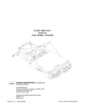
ALPHA 100K TMA MANUALFOR MODEL TMA8190ENERGY ABSORPTION SYSTEMS, INC.A Quixote CompanyCorporate Offices:One East Wacker Dr., Chicago, IL 60601-2076Telephone: (312) 467-6750FAX: (312) 467-1356Engineering and Manufacturing Facilities:Rocklin, CAPell City, ALRevisionFDate 2/25/99E.A.S.I. Part No. 2750122-0000
ALPHA100KTMAALPHA 100K TMA General InformationTable of ContentsSystem OverviewGeneral Information . 2The ALPHA 100K TMA is a lightweight, highly efficientattenuator system designed for installation on the back oftrucks. The system consists of an aluminum cartridgewith a Durashell Nose, a backup and a backup supportstructure with five auxiliary aluminum cartridges (totalweight is approximately 1180 kg [2600 lbs]).Installation Instructions . 4Detail Drawings . 8AOperation Instructions . 9Attaching and Detaching . 11General Maintenance . 14Repair Instructions . 17Limitations and Warnings . 19Important Introductory NotesThis manual contains important information on theALPHA 100K Truck Mounted Attenuator (TMA), Model8190, 90 degree Tilt System. Proper installation andoperation of the ALPHA 100K TMA is essential to assuremaximum performance. Take the time to review thisentire manual thoroughly prior to installing and/or operating the Energy Absorption Systems, Inc. TMA.If you need additional information, or have any questionsabout the ALPHA 100K TMA, please call Energy AbsorptionSystems' Customer Service Department at 1-888-32-ENERG.RETURN GOODS POLICYBefore returning any goods for credit pleasecontact Energy Absorption Systems Inc. Customer Service Department at 1-888-32-ENERG oryour local distributor for proper instructions.2The assembled components of the ALPHA 100K TMASystem are designed for attachment and detachmentfrom the truck, as one unit. Jacks attached to thecartridge, backup & support frame facilitate this process.Only the underride assembly remains attached to thetruck.The 350DX (rear) cartridge is equipped with one rearmounted steel wheeled jack, which when retracted, actsas a skid protector. The two rear bottom, outside cornersof the cartridge are protected by plastic skid protectors.The 350DX cartridge is equipped with a standard trailerlighting system, including brake lights, tail lights, turnsignals, and an ICC bar light. Wiring is normally routedthrough and secured inside the cartridge.Refer to Figure 10 for a diagram of the ALPHA 100K TMASystem.The hydraulic tilt system consists of a pump, 12 or 24 voltDC motor, cylinders, hoses, switches, wiring and othersubcomponents which enable the 350DX cartridge to tilt90 degrees from horizontal. Included with this packageis a mechanical locking device to secure the cartridge inthe 90 degree position. For greater ground clearance, theentire system can be tilted 10 degrees from horizontal.The hydraulic tilt system is extremely useful whentransporting or maneuvering the truck in confined areas.The hydraulic system is shipped factory assembled andmounted to the backup and the support frame assembly.
Crash PerformanceWITH TMAThe ALPHA 100K TMA System is designed for truckswith a Gross Vehicle Weight (GVW) ranging between 7300kg [16,090 lbs] and 12 000 kg [26,460 lbs]. To achieveoptimum TMA performance, the traveling weight of thevehicle should be between 7300 kg [16,090 lbs] and9000 kg [19,845 lbs].SKID DISTANCEEnergy Absorptions Systems TMAs have consistentlyproven to be effective in. WITHOUT TMAsafely stopping the errant motoristprotecting the shadow vehicle occupantsminimizing damage to the shadow vehicleA minimum 7300 kg [16,090 lbs] truck equipped with theALPHA 100K TMA system has a forward skid distance (rollahead) of less than 6 m [20 ft] during impact by either a820 kg [1808 lbs] or 2000 kg [4410 lbs] vehicle travelingat a design speed of 100 km/h [62 mph]. This forwardskid distance is dependent on the truck wheels beinglocked, the transmission in second gear, and the parkingbrake set with the truck situated on clean dry pavement.Note: The use of a lighter weight shadowvehicle can result in a greater, less predictableroll ahead distance.SAME SKID DISTANCEFigure 1THE USE OF A TMA ON THE BACK OF A TRUCK:DOES Safely stop the errant motorist* Protect the shadow vehicle occupants* Reduce damage to the shadow vehicle*DOES NOT Affect the skid (roll ahead) distance of an impactedtruck KEEP WORK CREWS CLEAR!CONTROLLING SKID DISTANCE (ROLL AHEAD): Skid distance is significantly increased and is lesspredictable for lightweight shadow vehicles Skid distance is reduced and is more consistentwhen heavier shadow vehicles are used. Recommended truck GVW is:12 000 kg [26,460 lbs.] Recommended Curb Weight 9 000 kg [19,845 lbs.]*DESIGN SPEED IMPACTS: 100 km/h [62 mph] for 820 and 2 000 kg [1808 and 4410lbs] vehicles.For Customer Service Call1-888-32-ENERG3
ALPHA100KTMAALPHA 100K TMA Installation InstructionsRequired Tools1. Welding equipment (for 1/2" plate)2. Cutting torch3. Hammer4. Drift pin or alignment pin5. Tape measure6. 1/2" drive socket wrenchRead and understand all instructions before beginning installation.Preparation1) Truck ballastPark on a level surface (use bubble level). The truckshould be as close to the final driving weight as possible.The entire TMA and underride weighs close to 1200 Kg[2,650 lbs]. Add an equivalent weight to the rear of thetruck to load the springs down to the proper height beforeattaching the underride. If ballast must be added toachieve the 7300 kg [16,090 lbs] minimum weight, addit at this time. It must be properly anchored to the truckto keep it in place during an impact. Ideally an adequatelysized truck that requires no ballast should be used.7. 1/2" drive sockets (1/2", 9/16", 5/8", 3/4", 15/16", 1", 1-1/8", 1-1/2")2) Underride Assembly8. Open end wrenches (1/2",9/16", 5/8", 3/4", 15/16",1", 1-1/8", 1-1/2")Before installing the ALPHA 100K TMA, the truck must firstbe equipped with a rigid Underride Assembly attached tothe rear of the truck frame which must be capable ofwithstanding an impact load of 200 kN [45,000 lbs] alongthe lower members. Parts and materials are supplied withthe ALPHA 100K TMA for installing an underride thatmeets the requirements specified (see Figure 2 & underride drawings for minimum requirements).9. 12" crescent wrenches (2)10. Carpenter’s 24" bubble level11. Marking implement (pencil, soap stone)TRUCK FRAME12. (2) Floor jacks (a forklift is recommended)13. Drill motor for 13/16" diameter bit14. 13/16" diameter bit and pilot drill for same15. Center punch16. Torque wrench17. Hydraulic fluid (use Dexron II or III fluid only)*SOCKET- OR -*Shipped with systemSTANDARDUNDERRIDEFigure 24TRUCK FRAME
Note: All welding must be performed by awelder certified to AWS D14.3-82 or AWSD1.1 and in accordance with underridedrawing.USE PROPER WELDINGTECHNIQUES TO KEEPPLATES FLAT AND SQUARERELATIVE TO EACH OTHERBUBBLELEVELTRUCK FRAMESPACER TUBESSPACER SPLICE (USEONLY ON REARSPACER TUBE)889mm[35.00"]LEVELGROUNDFLUSH WITHEND OF FRAMEUNDERRIDE SOCKETRECEIVERFigure 4Inspect ShipmentWITHOUT SPACERSSOCKET HITCH (LEFT SIDE SHOWN)CAUTION: DO NOT CUT FRAME CROSS MEMBER WHICHTIES INTO OUTBOARD LEAF SPRING HANGERS*CAUTION: TRUCKFRAME IS HIGHCARBON STEEL. TOAVOID CRACKING, DONOT WELD OR APPLYEXCESSIVE HEAT TOBOTTOM FLANGEFORWARD OF REARMOST LEAF SPRINGHANGER*UNDERRIDE889 mm [35.00"]13 mm [0.50"]LEAF SPRING HANGERTRUCK FRAMESTANDARD UNDERRIDE MOUNTING PLATECUT OUT CROSS PIECES ONCE INSTALLEDLEVEL GROUNDNOTE: LEFT & RIGHT UNDERRIDESOCKET RECEIVERS MUST BE PARALLEL WITH EACH OTHER AND LEVELWITH SPACERSTRUCKFRAMECheck shipping list against actual parts to make sure allitems were received. Review drawing package and familiarize yourself with the assembly and part numbers.Installation Procedures1) Attach cartridge to the backupA. Attach mast and shock absorbers as shown inFigure 6 and installation drawings. Be sure innertabs of mast face forward toward truck. Attach29" cables as shown in Figure 7 and installationdrawings. Take all slack out of 29" cables byadjusting turnbuckles attached.B. The backup and support frame are partially preassembled at the manufacturing facility. Attachthe 350DX cartridge to the backup using the 1/2inch bolts (attached to cartridge), nuts and washers (see Figure 5). Torque nuts to 122 Nm [90 ft-lbs].1/2" NUTS &WASHERSBACKUPLEVEL GROUNDSTANDARD UNDERRIDE350DX CARTRIDGEFigure 3Figure 5For Customer Service Call1-888-32-ENERG5
ALPHA100KTMAALPHA 100K TMA C. Attach the free end of the 5/16" diameter x 80"long rear tension cables to the left and right sidesupport brackets using the 5/8" nuts provided(see Figures 6, 7 and Detail "A"). Tighten nuts untilslack is removed from cable, then tighten oneadditional complete turn. "Double" nut to preventloosening.INNER TABSIMPORTANT: CABLE MUST BE PROPERLYTENSIONED OR DAMAGE TO CARTRIDGECOULD RESULTMASTSHOCKABSORBERSUPPORTBRACKET(LEFT SIDE)SEE DETAIL "A"FREE END OF REARTENSION CABLE(2) 5/8" NUTSDetail AFREE END OF 5/16" DIAMETER X 80" LONGREAR TENSION CABLE (LEFT SIDE)Figure 62) Lift systemLift support frame, backup and cartridge enough to extend cartridgejack, reposition backup jacks and rotate support frame jacks tovertical position (see Figure 15). Extend jacks to “raise” the 350DXcartridge height to 305 mm /- 6 mm [12" /-1/4"] at front, 330 mm /- 6 mm [13" /-1/4"] at rear (see Figure 7).29" CABLETENSION CABLE PER 1) C, ABOVE ORON DECAL ON CARTRIDGE305 /-6 mm[12" /-1/4"]Figure 76330 /-6 mm[13" /-1/4"]
8) Install electrical sockets10) Complete the hydraulic circuitInstall electrical sockets to rear of truck (see Figure 17 andsheet 1 of drawing set). Make sure that the electric cordon the backup and cartridge can reach this location.Mount the two cab switches inside the cab (see Figure 16and Hydraulic Assembly drawing) within easy reach ofthe driver and install the “Caution” decal supplied with thepush button, near the switches. Mount the switch box inthe support provided on the side of the 100K supportframe on the passenger side of truck (see Figure 9). Thehydraulic system is shipped pre-assembled and mountedon the backup and support frame assembly as shown onthe Hydraulic Assembly Drawing (#3526031-0000).9) Attach the support frame assemblyA. Position and attach the support frame attachmentbrackets to the mounting plates which have beenwelded to rear of truck frame or socket hitchusing the 1x3 1/2 inch grade 8 bolts provided(see Figure 8).SUPPORT FRAMEATTACHMENTBRACKETSOCKET HITCH ORSTANDARD UNDERRIDEMOUNTING PLATE1" NUTSWITCH BOXSWITCH BOX SUPPORT1" FLATWASHER1" LOCKWASHER1" X 3 1/2" BOLTFigure 8BREATHERCAPB. Attach the Support Frame Assembly to the attachment brackets using the upper set of holes in thesupport frame, with the (2) 1 1/4 inch diameterpins provided. The retaining pins should be onthe inboard side of the frame, and oriented correctly. (See Figure 14 and detail drawings).PUMPRESERVOIRFigure 9C. Attach the lower support bracket to the mountingplates using the (4) 1" x 3 1/2" grade 8 bolts, nutsand washers provided (see Figure 14).For Customer Service Call1-888-32-ENERG7
ALPHA100KTMAALPHA 100K TMA 11) Secure jacksNote: Do not run down truck battery.16) Verify locking mechanismSecure the five jacks into their travel positions. (see Figure 15).Make sure the latch mechanism securely locks the cartridge in the 90degree "UP" position.12) Adjust the height and levelness of thecartridgeDouble check the height and levelness of the 350DX cartridge relativeto the ground (305 mm /- 25 mm [12 in /- 1 in]). If necessary,the height of the 350DX cartridge can be adjusted 2 inches upward byusing the lower set of holes in the support frame. If it is not level,adjustment can be made by using the 1/4 inch and 12 gage thickshims provided (see Figure 10).13) Verify turn/stop/tail lightsPlug in the cartridge and backup plugs as well as the pump's batterycable (to the positive terminal) and verify that all turn/stop/tail lightsare working properly.14) Verify position of hydraulic/electrical linesCheck location of all hydraulic and electrical lines to make sure theywill not be damaged during tilting of system up or down.Note: If mechanism will not lock, vary thelength of the cylinder by turning the clevis oneor two revolutions (see Figure 12).Caution: Each time the cartridge is raised,the operator should verify that the latch isfully locked (cartridge will bleed down Iflatch is not fully locked) before allowinganyone behind the system.17) Final checkCheck tightness of all fasteners. Check all tension cables to verify thatthey are properly attached and that all slack is removed. Use a wickingtype threadlocker on all stud end attachments. Verify the 100K supportframe is securely latched in its fully extended position. Double checkheight and levelness of cartridge.18) Ready to use15) Verify / adjust the flow rate of thehydraulic systemRead the Operation Instructions, then cycle the system up and downseveral times to relieve air from the system. If necessary, adjust thebleed-down rate using the flow control valves (see Figure 12). Cartridge should bleed down from 90 degrees to horizontal in 15-30seconds. Bleed down from 10 degrees should be about 15 seconds(Refer to Hydraulic Assembly Drawing).The ALPHA 100K TMA is now ready for use. To ensure proper and safeoperation, all TMA users should be given operating and safety instructional training, as given in this manual and as specified by the owneror state.4739 [15'-6 1/2"]2134 [7'-0"]2522 [8'-3 1/4"]ADD SHIMS HERE914 /-6 mm [36" /-1/4"]8305 /-25 mm [12" /-1"]Figure 10
Safety Instructions1) Before tilting the system up or down, operator mustbe trained for proper operation, and must be sure allpersons are standing clear. The latch mechanismmust be seated completely in its locked positionbefore a
welder certified to AWS D14.3-82 or AWS D1.1 and in accordance with underride drawing. ALPHA 100K TMAALPHA 100K TMA 6 2) Lift system Lift support frame, backup and cartridge enough to extend cartridge jack, reposition backup jacks and rotate support frame jacks to vertical position (see Figure 15). Extend jacks to “raise” the 350DX cartridge height to 305 mm /- 6 mm [12" /-1/4 .