Transcription
TECHNICAL SUPPORT: 1-800-403-3279Installation / Operating Instructions forEasy Radiant “Works”EZ DUZZITInfrared Radiant Tube Heater/Radiateur a tube rayonnant a infrafougeA COPY OF THIS MANUAL MUST BE PROVIDED TO THE END USERMODEL NUMBERSED-40UED-40S40,000 BTUHLIQUID PROPANE OR NATURAL GASTECHNICAL DATA FOR STRAIGHT AND U CONFIGURED HEATERSETL LISTEDCOMFORMS TOANSI STD Z83.20CERTIFIED TOCSA STD 2.34CGA/CSA STD 2.17The installation must conform with local building codes or, in the absence of localcodes, the National Fuel Gas Code, ANSI Z223.1/NFPA 54, or the Natural Gas and PropaneInstallation Code, CSA B149.1 The latest edition Electrical Code PART 1 CSA C22.1 in Canadaand ANSI/NFPA NO 70 in the USA must also be observed.It is beyond the scope of these instructions to consider all conditions that may be encountered.WARNING: Improper installation,adjustment, alteration, service or maintenancecan cause property damage, injury or death.Read the installation, operating and maintenanceinstructions thoroughly before installing orservicing this heater.AVERTISSEMENT. Une installation, unréglage, une modification, une réparation ou unentretien incorrect peut entraîner desdommages matériels, des blessures ou la mort.Li sez attentivement les instructionsd’installation, de fonctionnement et d’entretienavant de procéder à l’installation ou àl’entretiende cet radiateur.
APPLIANCE OVERVIEWThe EZ Duzzit Shop/Garage heater is supplied with a region specific ½” flexible gasconnector, a 24V thermostat, and a 4” OD side wall exhaust termination cap.ED-40SOVERALL LENGTH:OVERALL WIDTH:OVERALL DEPTH:WEIGHT:ED-40U22’ / 670 cm13” / 33 cm10” / 25 cm90 lbs. / 41 kg.BUILDING SPAN REQ: 25’ / 762 cmCEILING HEIGHT REQ: 8’ / 244 cmOVERALL LENGTH:OVERALL WIDTH:OVERALL DEPTH:WEIGHT:12’ / 366 cm22” / 66 cm10” / 25 cm90 lbs. / 41 kg.BUILDING SPAN REQ: 15’ / 457 cmCEILING HEIGHT REQ: 8’ / 244 cmNOTE: Above appliance dimensions represent the maximum at anypoint in the appliance. Dimensions at certain points of theappliance may be less.WARNINGTHIS AND EVERY GAS FIRED PRODUCT MUST ONLY BE INSTALLED ORSERVICED BY A PROFESSIONALLY LICENSED AND QUALIFIED GASTECHNICIAN. INSTALLING GAS FIRED APPLIANCES WITHOUT THE REQUISITELISCENCE, KNOWLEDGE AND/OR UNDERSTANDING OF ALL RELEVELANTCODES AND REQUIREMENTS CAN RESULT IN FIRE, EXPLOSION, PROPERTYDAMAGE, INJURY, DEATH, BE CONSTRUED AS NEGLIGENCE, AND/OR CAUSETHE CANCELLATION OF IN FORCE LOSS/LIABILITY INSURANCE COVERAGE.ENSURE THAT ALL WARNINGS, NOTICES, AND INSTRUCTIONS IN THISMANUAL ARE FULLY READ AND UNDERSTOOD BEFORE INSTALLING THISAPPLIANCE. IF UNCLEAR ON ANY PORTION OF THIS MANUAL, PLEASECONTACT THE MANUFACTURER FOR CLARIFICATION PRIOR TOINSTALLATION.2
SAFETY ALERTDo not store or use gasoline or other flammablevapors and liquids in the vicinity of this or anyother gas fired appliance.ALERTE DE SÉCURITÉNe pas stocker ou utiliser d'essence ou d'autresvapeurs et liquides inflammables à proximité decet appareil ou d'un autre appareil à gazFOR YOUR SAFETYIF YOU SMELL GASConsignes De SecuriteSI VOUS SENTEZ UNE ODEUR DE GAZ1. Open windows1. Ouvrez les fenetres2. Do not touch electrical switches, or telephone2. Ne touchez pas aux interrupteurs electriques3. Extinguish any open flame4. Immediately call your fuel supplier from aneighbor’s phone5. If your gas supplier is not available, call thefire department6. Do not attempt to light this or any otherappliance3. Eteignez toute flamme nueWARNINGThis appliance may have sharp edges andcorners. Wear protective clothing such as glovesand protective eye wear when servicing this orany other applianceFor indoor installation only.Not for use in residential dwellings.4. Contactez immediatement compagnie de gaz5. Si votre fournisseur de gaz n’est pasdisponible, appeler les pompiers.6. Ne pas tenter d’allumer ceci ou aucun autreappareil.ATTENTIONCet appareil peut avoir des arêtes vives et descoins. Porter des vêtements de protection telsque des gants et des lunettes de protection lorsde l'entretien de cet appareil ou de tout autreappareil.Installation a l’interieur seulement. Ne pas utiliserpour le chauffage d’habitationsGas SupplyManifold PressureN.G.3.5” W.C.Propane10.0” W.C.Electrical120 volts 60HzMin. Inlet PressureMax. Inlet PressureMax. OutletPressure7.0” W.C.14.0” W.C.11.5” W.C.14.0” W.C.Starting CurrentRunning Current3.5” W.C.10.0” W.C.Gas ConnectionCombustion AirInletVent Connection½ in. N.P.T.4” O.D.ThermostatControl3 amps1 amp120V (Standard)24V (factory ready,optional)Ignition System: 120V Hot Surface Ignition4” O.D.3
CLEARANCES TO COMBUSTIBLESClearances tocombustiblesTop (AboveReflector)All Models4” (10 cm)Back (Back ofangledreflector)4” (10 cm)SidesBelow(Reflectors flat)Below (Reflectorsangled)18” (46 cm)32” (92 cm)32” (76 cm)The clearance to combustible materials represents the minimum distance that must bemaintained between the heater and a nearby surface.The stated clearance to combustible materials represents the minimum distance thatmust be maintained between the outer heater surface and a nearby surface. The statedclearance to combustibles represents a surface temperature of 90 degree Fahrenheit(32 degrees Celsius) above room temperature. Building material with a low heattolerance (such as plastics, vinyl siding, canvas, tri-ply, filmy materials, fabrics, etc.)may be subject to degradation at lower temperatures. It is the installer’s responsibility toassure that adjacent material are not subject to degradation.In a parking structure, a sign with a warning statement that an overhead heater ispresent should be installed in a visible location. Minimum required clearances below theheater should be clearly visible so that appropriate distances to combustibles will bemaintained to vehicles.In locations used for the storage of combustible materials, signs must be posted tospecify the maximum permissible stacking height to maintain the required clearancesfrom the heater to the combustibles, and that such signs must either be posted adjacentto the heater thermostats or in the absence of such thermostats in a conspicuouslocation. For your convenience a sign is provided with these instructions. (A samplestacked combustibles warning sign is included in the last page of this manual). Seeinformation on “maximum stack height under appliance”.In addition to stored or stationary material, consideration must also be given tomoveable objects such as cranes, vehicles, and overhead doors, and structural objectsthat may have their own specified minimum clearances to heat sources, such assprinkler heads, electrical and gas lines, and electrical fixtures.Minimum clearances (cm and inches) from combustibles are measured from the radiantsurface.Clearances are reduced by 1/3, 15 ft (4.6 m) from the burner.4
CLEARANCES TO COMBUSTIBLES (CONT.)For installation at elevations above 2000 ft (610 m), the appliance shall be de-rated 4percent for each 1000 ft (305 m) of elevation above sea level. Required clearancesapply to the appliance rated input, not the de-rated equivalent.WARNINGLocation of flammable or explosive objects, liquids or vapors close to the heater maycause fire or explosion and result in property damage, injury or death. Do not use, storeor locate flammable or explosive objects, liquids or vapors in close proximity to theheater. Ensure that adequate distance is maintained from the appliance to any suchmaterial that the material cannot reach temperatures that would approach potentialflashpoint/ignition/explosion thresholds.Provide adequate space around the burner and off the gas connection end of the burnerto allow for servicing.Minimum distance from the radiant surface to the floor in non-agricultural installations is7 ft (2.1 m) in Canada, and 8 ft (2.4 m) U.S.A.Minimum clearances (inches and cm) from combustibles are measured from radiantsurface. The clearances are reduced by 1/3,15 ft (4.6 m) from the burner.MAXIMUM STACK HEIGHT BELOW APPLIANCEIn locations used for storage of combustible materials, signs must be posted specifyingthe maximum stacking height to maintain the required clearances from the heater tocombustibles.For maximum stacking height, deduct listed appliance “below” clearance from thedistance from the floor to the appliance emitter tubes.The signs must be posted either adjacent to the infrared heating system thermostats orin the absence of such thermostats, in a conspicuous place.See suitable example of warning sign on last page of these instructions.5
WARNINGTHIS HEATER MUST BE INSTALLED AND SERVICED BY A TRAINED GASSERVICE TECHNICIAN ONLY. READ AND UNDERSTAND THESE INSTRUCTIONSTHOROUGHLY BEFORE ATTEMPTING TO INSTALL, OPERATE OR SERVICE THEEASY RADIANT WORKS HEATER. FAILURE TO COMPLY WITH THESEWARNINGS AND INSTRUCTIONS, AND THOSE ON THE HEATER COULD RESULTIN PERSONAL INJURY, DEATH, FIRE, ASPHYXIATION, AND / OR PROPERTYDAMAGE.DO NOT STORE OR USE GASOLINE OR OTHER FLAMMABLE VAPOURS ANDLIQUIDS IN THE VICINITY OF THIS OR ANY OTHER GAS FIRED APPLIANCETHIS APPLIANCE MAY HAVE SHARP EDGES AND CORNERS, WEARPROTECTIVE CLOTHING SUCH AS GLOVES AND PROTECTIVE EYE WEAR WHENSERVICING THIS OR ANY OTHER APPLIANCE.APPLICATIONThis gas fired radiant tube heater may be installed for heating of workshop / garages /commercial / industrial / agricultural / non-residential type spaces. It is beyond the scopeof these instructions to consider all conditions that may be encountered. Installationmust conform with all local building codes or, in the absence of local codes, to theNational Fuel Gas Code, ANSI Z223.1/NFPA54 in the U.S.A. or the Natural Gas andPropane Installation Code, CSA B149.1 in Canada. The latest edition Electrical CodeANSI/NFPA N0 70 in the U.S.A. and PART 1 CSA C22.1 in Canada must also beobserved.This appliance is approved for use in an attached garage only when required buildingcodes have been met for isolation/separation of the garage from the interior of theresidence, all required fire and air separations/barriers are in place, and all constructionis compliant with all required building and fire codes for such spaces. In no case canthis appliance be installed inside of a residence or domicile including basements,crawl spaces, storage areas, attics, living areas, or other any other attached areasthat are not isolated from the building as required by building code.Installation of a gas fired tube heater must conform to all heating installation designprocedures including clearance to combustibles, connection to the gas and electricalsupplies, and ventilation.This heater is not for installation in a Class 1 or Class 2 explosive environment. Ifinstallation of this equipment is in question, consult with local authorities havingjurisdiction (Fire Marshall, labour department, insurance underwriter, or others).Revisions or updates to codes and/or standards may require revision to equipment andinstallation procedures. In case of discrepancy, the latest revisions of applicable codes,standards, and installation manuals will supersede previous versions.6
WARNINGFLAMMABLE/EXPLOSIVE/CORROSIVE VAPORSWhere there is the possibility of exposure to combustible airborne materials or vapour,consult the local fire inspector's office, the fire insurance carrier or other applicableauthorities for approval of the proposed installation.Do not use in an atmosphere containing halogenated hydrocarbons or other corrosivechemicals. Some compounds in the environment can cause an accelerated rate ofcorrosion to the heat exchanger.The heater manufacturer cannot anticipate all types and chemical composition ofpossible contaminants at project sites. Consult with project site safety, health andengineering staff and/or local authorities having jurisdiction such as the Fire Marshalland Department of Labour for possible contaminants and any conflict with theinstallation of hot surface heating equipment.WARNINGHEATER EXPANSIONIt is a normal condition that during heat-up and cool-down a tube heater will expand andcontract. Allowances for heater expansion must be made in the gas connection, ventingand combustion air ducting. Consider that the heater will expand in length as much as½ inch (12.5 mm) or more for every 10 ft (3 m) of system length. Typically, the greaterthe firing rate, the greater the expansion. Improper installation, alteration, or adjustmentcan result in property damage, injury or death.WARNINGGAS CONNECTIONImproper installation, connection, or adjustment can result in property damages, toxicgases, asphyxiation, fire, explosion, injury and/or death. Using an approved flexible gasconnector in the USA and Rubber Type 1 hose connector in Canada, the gas supply tothe heater must be connected and tested in accordance with all local, state, provincial,and national codes (ANSI Z223.1/NFPA 54 in USA: B149.1 in Canada) and as indicatedin the manual. See: GAS SUPPLY, HEATER EXPANSION, AND FLEXIBLE GASCONNECTION.7
WARNINGVENTINGInadequate venting of a heater may result in asphyxiation, carbon monoxide poisoning,injury or death. The heater may be directly or indirectly vented from the space. Ventingmust be in accordance with all local, state, provincial, and national codes (ANSIZ223.1/NFPA 54 in USA; B149.1 in Canada) and as indicated in this manual.WARNINGSTART-UP SMOKE CONDITIONDuring start up, the heating of material coatings used in the production process of tubesand reflectors will create smoke and/or odors during the initial period of operation. Thiscondition is normal and temporary. Ensure that there is sufficient ventilation toadequately clear any smoke and/or odors from the space. Notify site and safetypersonnel to ensure that alarm systems are not unduly activated.LABOUR REQUIREMENTSTwo persons are required to safely install this equipment. Wear gloves and otherrequired safety protection.INSTALLATION IN COMMERCIAL AIRCRAFT HANGARSLow intensity radiant tube heaters are suitable for use in aircraft hangars when installedin accordance with the latest edition of the Standard for Aircraft Hangars, ANSI/NFPANo. 409 in the USA, or the Canadian Natural Gas and Propane Installation Code,B149.1A minimum clearance of 10 ft (3 m) above either the highest fuel storage compartmentor the highest engine enclosure of the highest aircraft, which may occupy the hangar.The clearance to the bottom of the heater shall be measured from the upper surface ofeither the fuel storage compartment or the engine enclosure; whichever is higher fromthe floor.A minimum clearance of 8 ft (2.4 m) must be maintained from the bottom of the heaterto the floor in other sections of the aircraft hangar, such as offices and shops, whichcommunicate with areas for servicing or storage. For proper mounting clearances, referto the clearances to combustibles in these installation instructions.Heaters must be located where they are protected from damage to aircraft and otherobjects, such as cranes and movable scaffolding.Heaters must be located so as to be accessible for servicing and adjustment.8
INSTALLATION IN COMMERCIAL GARAGES AND PARKINGSTRUCTURESLow intensity heaters are suitable for use in commercial garages when installed inaccordance with the latest edition of the Standard for Parking Structures, ANSI/NFPA88A, or the Standard for Repair Garages ANSI/NFPA No. 88B, or the Canadian NaturalGas and Propane Installation Code, B149.1In a parking structure, a sign with a warning statement that an overhead heater ispresent should be installed in a visible location. Minimum required clearances below theheater should be clearly visible so that appropriate distances to combustibles will bemaintained to vehicles.WARNINGINSTALLATIONS OTHER THAN SPACE HEATINGUse for process or other applications that are not space heating will void the productswarranty. Process application requires field inspection and/or certification by localauthorities having jurisdiction.IMPORTANTSingle or multiple heater placements must be such that continuous operation ofheater(s) will not cause combustible material or materials in storage to reach atemperature in excess of ambient temperature plus 90 degrees Fahrenheit (32 degreesCelsius).It is the installer’s responsibility to ensure that building materials with a low heattolerance, which may degrade at lower temperatures, are protected to preventdegradation. Refer to “Clearance to Combustibles” information in these installationinstructions.GENERAL INSTALLATION PROCEDUREPRE-INSTALLATION SURVEYIt is recommended that a full heating design, including a heat loss calculation beconducted. Heater sizing and placement must consider available mounting height,sources of heat loss, and clearances to combustibles with respect to stored material,moveable objects (cranes, vehicles, lifts, overhead doors, etc) sprinkler systems, andother obstructions on the site. Consideration must also be given to vent / ductplacement and the allowable combined lengths of vent and duct.- Carefully survey the area to be heated and place the burner and combustionchamber in the coldest area if possible.- The heater shall be hung in such a fashion so as to conform with theclearances to combustibles described on the name plate.- Clearances to combustibles must be maintained from vehicles parked below.- Adequate clearances must be maintained for installation in public garagesand airplane hangars.- Verify location with respect to the building construction and equipment, so asto provide sufficient clearances and accessibility for servicing.9
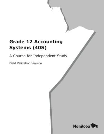
PRE-INSTALLATION SURVEY (CONT.)- The installation must comply with local codes and CAN/CGA B-149.1 in-Canada or the National Fuel Gas codes ANSI Z 223.1 (NFPA 54) in theUnited States.Ensure site electrical requirements are met. Consult the latest editionElectrical Code PART 1 CSA C22.1 in Canada and ANSI/NFPA NO 70 in theUSA.The heating system must have gas piping of the correct diameter, length, andarrangement to supply adequate fuel to allow the appliance to functionproperly.APPLIANCE INSTALLATIONStraight, L-Shaped & “U” shaped Heaters------Identify and verify all components of tube heater prior to installation.Appliances ship in components to be assembled on site. Ensure that correctnumber of primary tubes (tube with sight glass that burner attaches to), andbaffle secondary tubes (secondary tube with baffle pre-installed, labeled) areaccounted for. Verify that all other components/accessories listed on the factorymaterial packing list are present and accounted for.Ensure all hanger supports are in line, and allow for level hanger suspension.Suspend hangers from anchors with suitably rated min. #10 chain, threaded rod,turnbuckle, etc., adhering strictly to the required hanger locations in the followingdiagrams.If hanger locations do not line up with framing as required for support, you mayneed to securely attach strapping/backing to the structure as required.Attach hanger supporting anchors securely, and directly into buildingstructure only – in no case should any support that anchors only intodrywall or other interior wall/ceiling facing be used for installing thisappliance. Refer to section “Suspending The System”Ensure that hanger is suspended in a manner that will allow free movement withlateral expansion/contraction of the appliance.The first hanger must be no more than 6 inches from the burner.For straight unit hangers, suspend from the top ring on the hanger if thereflectors are to be horizontal, and the side ring of the reflectors are to be angled.For U configured units, each side of the hanger must have its own chain andanchor. IMPROPER HANGER PLACEMENT CAN CAUSE THE RADIANT TUBETO WARP AND VOID WARRANTY.With hangers in place, the primary tube, and subsequent secondary tube cannow be placed in the hangers. Self tapping screws are provided to be installedinto the expanded end of the radiant tube. Slide the tubes together making surethat the first tube is inserted all the way into the expanded end of the secondarytube. Install the self-tapping screws at 120 degree intervals to secure the twotubes together. The self-tapping screw holes must be adequately sealed duringinstallation using a suitably rated high temperature RTV silicone sealant.Suitably rated high temperature RTV silicone may be applied around tube joints.U-shaped models: connect the 180 degree bend to the radiant tube and securelytighten with self tapping screws provided.10
Straight, L-Shaped & “U” shaped Heaters (Cont.)-----If using 90 degree elbow on a model ED-40-S unit to achieve an “L” configuration(Part # AC1210), install the elbow between the primary and secondary tube, andsecure using the same methods above. Ensure that all lengths of tube areadequately supported, using no less than 2 hangers for each 10’ of total tubelength.U-shaped models: connect the 180 degree bend to the radiant tube and securelytighten with self tapping screws provided using the methods described above.Make sure to secure all tube joints using the 3 screws provided in 120 degreeintervals as indicated in the tube assembly diagram below.All ED series units require a baffle. The baffle must be installed at the ventend, located at the extreme opposite end of the heater from the burner.Baffles are pre-installed in a 10’ section of tube and are clearly labeled.Reflectors can now be placed in the hangers. To prevent “walking” of thereflectors, the first and second reflector can be joined together at the overlap witha sheet metal screwWith the radiant tube and reflectors now installed, the burner can be fitted on theprimary tube and secured using the pre-installed set screw. The burner does notrequire its own hanging support provided the first hanger is no more than 6inches from the burner joint. If the first hanger is more than 6 inches from theburner joint, warping of the primary tube may occur and the warranty willbe void.Connect the burner to the gas supply using a suitably approved flexible gasconnector as outlined in this manual.Install exhaust/intake air venting as outlined in this manual.Install thermostat control wiring as outlined in this manual.TUBE ASSEMBLYREFLECTOR EXTENSIONSReflector extensions (part number P-1930) may be installed on one side or both sides ofthe reflector as required to reduce lateral heater output on one or both sides of the unit.Reflector extensions are 10 ft long x 9”. Drill 3 holes per reflector, and secure extensions toreflector by means of field provided S hooks.11
12
13
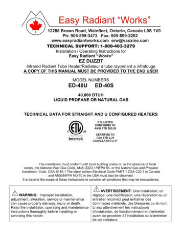
SUSPENDING THE SYSTEMWARNINGInadequate or improper suspension of the tube heater can result in collapse ofthe system, property damage, risk of fire/explosion, personal injury and/or death.It is the installer’s responsibility to ensure that the hardware and structural supports fromwhich the heater is suspended are sound and of adequate strength to support theweight and expansion forces of the heater. In no case should any support thatanchors only into drywall or other interior wall/ceiling facing be used forinstalling this appliance.Consider that the heater will expand in length as much as ½ inch (12.7) or more forevery 10 ft(3 m) of system length. Typically, the greater the firing rate, the greater the expansion.Survey the available structural supports, considering the system configuration and heatrequirements of the area to establish the optimum heater location. Locating a heaterdirectly under joists or beams, or installing supplemental steel support rail or angle ironcan substantially reduce labor and material requirements. Hardware with a minimum 60lbs (27 kg) workload must be used at each heater suspension point. Connect thestructure using typical hardware as illustrated below or by other mechanically soundmeans.14
ELECTRICAL/CONTROLSELECTRICAL REQUIREMENTS120VAC / 60 Hz / Single Phase / 1A / 3 Wire GroundedStarting Current: 3 ampsRunning Current: 1 amp1. Electrical installation must be grounded in accordance with CSA Standard C22.1part 1 in Canada or The National Electrical code ANSI NFPA 70 (latest edition) inthe United States.2. Polarity of line voltage and neutral wires must be maintained.3. The total load of all heaters in a circuit must be considered so as to not overloadthe circuit.4. Ensure that thermostat wire polarity is maintained.THERMOSTAT CONTROLHeaters are designed for compatibility with either 120 Volt (line) thermostat controllersor 24 Volt thermostat controllers. For use with 120 Volt controllers, the heater must beplugged into a “switched” 120 Volt duplex receptacle, where the receptacle is switchedby the thermostat controller. Heating zones may be established where one 120 Voltthermostat controls more than one heater, provided the total heater electrical load doesnot exceed the maximum allowable amperage on the circuit.For a 24 volt thermostat control, plug the heater into a 120 Volt duplex receptacle.Remove the jumper wire on the control box marked “24 Volt thermostat” and connectthe thermostat wire to the terminals. Do not allow live thermostat wires to contactappliance chassis, or damage to the appliance transformer/controls may occur.Ensure that if the thermostat has a heat anticipator, the heat anticipator is set atmaximum. When using a 24 Volt thermostat, only one heater may be directly controlledby one thermostat unless a system of field supplied relays are utilized.For 2 stage appliances, connect wires as marked on appliance terminal. Polarity mustbe maintained. If required, connect thermostat ground to appliance ground post.15
GAS SUPPLYPIPING1. All gas piping and connections shall be made in accordance with all applicablelocal codes and the latest versions of CAN/CGA B-149 or ANSI standard Z223.1.2. Connect the burner to gas supply with flexible gas connector.3. A drip leg must be installed in the gas line at the heater inlet connection teefollowed by a pipe drop to the heater. Failure to provide a drip leg could result incondensation and foreign matter passing into the gas valve. Failure to install adrip leg in the gas line can cause property damage, injury or death and will voidthe heater warranty.16
CAUTION: Ensure that flexible gas connectors are installed correctly to allow forheater expansion/contraction during operation. Install flexible connectors as follows:WARNINGNever use a match or other flame to test for gas leaks. Use soap and water solutionto check for leaks to all connections and joints and if bubbles appear, leaks havebeen detected and must be corrected. Never operate an appliance with leaking fuelsupply system. The supply system should be checked first with appliance turned offfollowed by another check while appliance is operating.GAS SUPPLY, HEATER EXPANSION, AND FLEXIBLE GASCONNECTIONThe required flexible gas connector must be used, and are available from EasyRadiant “Works”. Flexible gas connectors used from alternate sources must adhereto the following Standards:The connection of a radiant tube type infrared heater to the gas supply line, inparticular taking into account the heater’s thermal expansion and contraction, thegas supply must be installed using:In Canada a type 1 hose connector that is certified as being in compliance with theStandard for Elastomeric Composite Hose and Hose Couplings for ConductingPropane and Natural Gas, CSA 8.1; and of a length of 36 6 in (91 15 cm) with anID of a least ½ in (12.7 mm).In USA an approved Stainless Steel Flexible Gas Connector certified for use on aninfrared radiant tube heater per the Standard for Gas Appliances ANSI Z21.24 CSA6.10. and comply with a 24 in (610 mm) to 36 in (91 cm) long connector with an ID ofa least 1/2 in (12.7 mm).Heaters installed with maximum thermal expansion of up to 2 in (50 mm) shall beinstalled with a 24 in (610mm) to 35 in (91 cm) long connector with an ID of a least1/2 in (12.7 mm) and;Heaters with maximum thermal expansion of up 3 in. (76.2 mm) shall be installedwith 36 in (91 cm) long connector with an ID of a least 1/2 in (12.7 mm) and;heaters with maximum thermal expansion of more than 3 in (76.2 mm), but less than6 in shall be installed with a 36 in (914 mm) long connector with an ID of at least 3/4in (19.05 mm).The distance between the distal mounting positions shall be measured with theappliance “OFF” at ambient temperature and at normal operating temperature. Thedifference between the two distances shall be used to select an appropriate flexibleconnector.Also the flue vent, and combustion air intake (if used) must be installed in such amanner that the normal expansion of the heater will be accommodated17
WARNINGHEATER EXPANSIONConsider that the heater will expand in length as much as ½ inch (12.5 mm) or morefor every 10 ft (3 m) of system length. In general, the greater the appliance firingrate, the greater the rate of expansion.This heater will expand in length as it heats up. It is a normal condition that duringheat-up and cool-down a tube heater will expand and contract. Allowances forheater expansion must be made in the gas connection, venting and combustion airducting. Improper installation, alteration, or adjustment can result in propertydamage, injury or death.The BTU input and the tube length determine the overall expansion that occurs. Atypical infrared tube installation will expand toward both the burner and the vent end.Compensation for normal gas supply pipe expansion and radiant tube heaterexpansion must be provided. All piping must conform to local codes.Provide a 1/8 in (3.2 mm) NPT plugged tapping, accessible for test gaugeconnection, immediately upstream of the gas supply connection to the heater.Test for leaks. All gas piping and connections must be tested for leaks after theinstallation is completed.The heater must be isolated from the gas supply piping system by closing itsindividual manual shut off valve (field supplied) during any pressure testing of thegas supply piping system.Apply soap solution to all connections and joints and if bubbles appear, leaks havebeen detected and must be corrected. Do not use a match or open flame of a
Infrared Radiant Tube Heater/Radiateur a tube rayonnant a infrafouge A COPY OF THIS MANUAL MUST BE PROVIDED TO THE END USER MODEL NUMBERS ED-40U ED-40S . This heater is not for installation in a Class 1 or Class 2 explosive environment. If installation of this equipment is in question, consult with local authorities having

![[SURVEY PREVIEW MODE] DLIS SURVEY - fao](/img/19/dlis-questionnaire.jpg)