Transcription
Form I-VP1 (Version A)INSTALLATION / OPERATION / MAINTENANCEApplies to:Model VP1 120V 60HzGas-Fired, Tubular, Radiant,Low-Intensity Infrared HeaterModel VP1Burner/Control Boxwith 20 - 80 ft Tube/Reflector LengthPart No. 270683
Introduction.Welcome to the new range of powered infra-redheaters. Local regulations may vary and it is theinstaller’s responsibility to ensure that suchregulations are satisfied.heaters specified in these instructions, due careand attention is required to ensure that workingat height regulations are adhered to.All installation, assembly, commissioning andservice procedures must be carried out bysuitable qualified competent persons andconform with local building codes, or in theabsence of local codes, with the National FuelGas Code ANSI Z223.1/NFPA 54 or theNational Gas and Propane Installation CodeCSA B149.1PLEASE READ this document prior toinstallation to familiarize yourself with thecomponents and tools you require at the variousstages of assembly.All Dimensions shown are in inches unlessotherwise stated.The manufacturer reserves the right to alterspecifications without prior notice.When assembling, installing, commissioningand servicing is undertaken on radiant tubeDocument Index.3.1 Tools Required3.2 Start up procedure1 Installation Requirements1.1 Health & Safety1.2 Heater Suspension1.3 Clearance to Combustibles1.4 Gas Connection & Supply Details1.5 Electrical Connections1.6 Ventilation Requirements1.6.1 Unvented Units1.6.2 Vertical Venting1.6.3 Horizontal Venting1.7 Fresh Air Intake1.8 Technical Details4 Servicing Instructions4.1 Tools Required4.2 Burner Description4.3 Burner Removal4.4 Burner Gas Injector Servicing4.5 Burner Head and Electrode Servicing4.6 Combustion Fan Assembly4.7 Radiant Tube Servicing4.8 Reflector Servicing4.9 Cleaning of Vent4.10 Re-commissioning after Service2 Assembly Instructions5 Spare Parts6 Troubleshooting Guide7 Replacing Parts2.1 Tools Required2.2 Assembly Notes2.2.1 Tubes2.2.2 Turbulators2.2.3 Brackets2.2.4 Couplers2.2.5 Reflectors2.2.6 End Caps (optional)2.2.7 Bends (where required)2.2.8 Burner/Fan Assembly2.2.9 Detailed Assembly Drawings7.1 Burner Controller Replacement7.2 Air Pressure Switch Replacement7.3 Gas Valve Replacement7.4 Optional Extra Kits8 User and Operating Instructions8.1 To Start Heater8.2 To Switch Off Heater8.3 Servicing3 Start Up Instructions1. Installation Requirements.1.1Health and SafetyA.Heater is intended for heatingnon-residential indoor spaces and shouldonly be installed where flammable gasesor vapors are not generally present.B.C.D.Heaters may be suspended eitherhorizontal or at any angle. See section1.3 for clearance dimensions.E.The installation must conform with localbuilding codes or, in the absence of local2codes, with the National Fuel Gas Code,ANSI Z223.1/NFPA 54 or the NaturalGas and Propane Installation Code, CSAB149.1.The unit shall be electrically grounded inaccordance with National Electric CodeANSI/NFPA 70 and Canadian ElectricalCode CSA C22.1.The heater may be installed in aircrafthangars in accordance with the Standardfor Aircraft Hangars, ANSI/NFPA 409and in automotive garages when in-
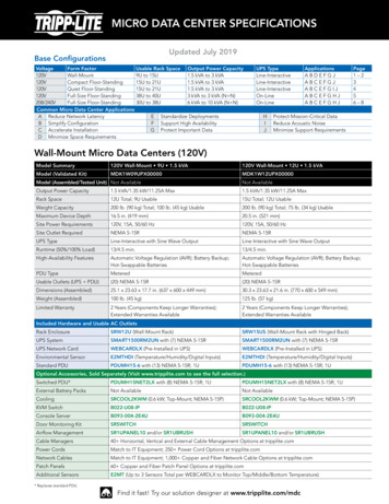
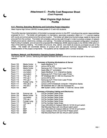
F.stalled in accordance with the Standardfor Parking Structures, ANSI/NFPA 88A,or the Standard for Repair Garages,ANSI/NFPA 88B, or theCanadianNatural Gas and PropaneInstallationCode, CSA B149.1, and are so marked.Ensure that minimum clearances will bemaintained to vehicles parked below theheater.purpose made to sound engineering practice orsupplied by others.The standard heaters are approved forinstallations between 0 - 2000ft (0 610m) for the US and 0 - 4500 ft(1370m) for Canada. Conversion kits areavailable on installations above theseheights in the USA.These methods are illustrated in Figure 1. Ifthere are any doubts as to the strength orsuitability of roof steelwork to which heaters areto be suspended, please refer to a Consultant,Architect or owner of the building.They must be adequately fixed and designed tocarry the whole weight of the heater. In theevent ofsuitable roof steelwork beingunavailable, additional steelwork should be fittedto enable vertical hangers to be used forsuspending the heaters.It is recommended that the heater is raised to itsfinal position once the assembly of the tube/bracket/reflector has been completed. Longertube assemblies may be raised in more thanone sub-assembly with final tube connectionmade in the air.The suggested mounting heights for heaters aregiven in the chart next page.Note: Any outdoor installations must beinstalled with a vent cap at the inlet andthe flue end.1.2Heater SuspensionAttachment to the heater support lugs shouldbe made by D shackle. The hanging attachments to overhead steelwork etc. must be1.3Clearance to Combustibles.WARNING:If not installed, operated and maintained in accordance with the manufacturer’s instructions,this product could expose you to substances in fuel or from fuel combustion which areknown to the state of California to cause cancer, birth defects or other reproductive harm.U TUBE VARIANTSEYE HOOKSNOTE.HOOKS ARE TOBE CLOSED UPAFTER ASSEMBLYSuitable Chain Working2/0 GA100lb.CHAINLoad Limit(TWISTED LINK, PLATED)EXHAUSTENDCHAIN55 SUSPENSIONBURNEREND3ON U TUBE VARIANTS THE HEATER SHOULDSLOPE DOWNWARDS TOWARDS THE BURNERHEAD AND ON LINEAR VARIANTS SHOULD SLOPEDOWNWARDS TOWARDS BURNER BY APPROX. ½”FOR HORIZONTAL INSTALLATIONSFigure 1. Recommended Methods of Heater Suspension.
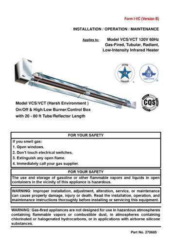
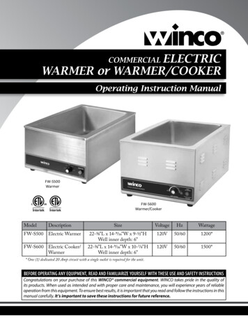
Minimum clearance to combustibles are shownin Figure 2. Refer to table 1 below.(such as plastics, vinyl siding, canvas, tri-ply,etc.) may be subject to degradation at lowertemperatures.IMPORTANT:The stated clearance to combustiblesrepresents a surface temperature of 90 F(50 C) above room temperature.Building material with a low heat toleranceTable 1It is the installer’s responsibility to assure thatadjacent materials are protected fromdegradation.Clearance to Combustibles, inches (cm)ModelAB1874 (188)29 (74)2574 (188)30B1C1C2C3D1D2E41 (105) 20 (51) / 10* (26)*8 (21)22 (56)8 (21)12 (31)12 (31)29 (74)41 (105) 20 (51) / 10* (26)*8 (21)22 (56)8 (21)12 (31)12 (31)74 (188)32 (82)41 (105) 20 (51) / 10* (26)*8 (21)22 (56)8 (21)16 (41)12 (31)3874 (188)39 (99)47 (120) 20 (51) / 10* (26)*8 (21)22 (56)20 (51)18 (46)12 (31)4574 (188)39 (99)48 (122) 20 (51) / 10* (26)*8 (21)22 (56)20 (51)18 (46)12 (31)5086 (219) 48 (122) 48 (122) 20 (51) / 10* (26)*11 (28)22 (56)20 (51)20 (51)12 (31)6086 (219) 48 (122) 48 (122) 20 (51) / 10* (26)*11 (28)22 (56)20 (51)20 (51)12 (31)* distance with end caps fitted.WARNING:Minimum clearance from the heater must be maintained from vehicles parked below heater.In all situations, clearances to combustibles must be maintained. Signs should be posted instorage areas to specify maximum stacking height to maintain required clearance tocombustibles. Such signs must either be posted adjacent to the heater thermostats or in theabsence of such thermostats in a conspicuous location.Refer to mounting clearance tables.4
B5EC1ServicedistanceAboveBurnerEnd view.SideventedASideunventedAboveReflectorBurner end.C2BelowheaterBB1Above outletunventedEndunventedD1Outlet end.C3Ensure that there is adequateprovision in the building forcombustion and ventilation air supply.Installation must meet minimumrequirements and appliciableapplicable codes.WARNING!.D2Return end onU tube heater0 to 55 AAngled view.Figure 2 Clearance to Combustibles.The minimum clearances to combustible materials are given in the tables below. Theseminimum distances MUST be adhered to at all times. Adequate clearance MUST be providedaround air openings into the combustion chamber and there MUST be suitable clearance foraccessibility and for combustion / ventilating air supplies.
1.4Figure 3. Correct orientation of Ball ValveGas Connection and SupplyWARNING: Before installation, checkthat the local distribution conditions,nature of gas and pressure, and adjustmentof the appliance are compatible.Gas FlowThe gas connection on the heater is ½” N.P.Tinternal thread.Gas FlowInjector sizes and manifold pressure for theburners are shown in the table 4. The gassupply piping and connections must be installedso that the minimum pressure stated isachieved.A gas shut off valve and union should be fittedin the gas supply line close to the heater and a⅛” N.P.T plugged tapping, accessible for testgauge connection, provided immediatelyupstream of the appliance gas inlet.Figure 4. Correct Installation of FlexibleGas ConnectionIt is essential to provide some flexibility in thefinal gas connection by use of an approvedflexible gas connector. See Fig 4.Take care when making a gas connectionto the heater not to apply excessive turningforce to the internal controls.Care must be taken to observe the minimumpipe bend diameter (minimum 10” - 250mm,maximum 14” - 350mm) & pipe expansiondistance (minimum 1⅛” - 28mm, maximum3¾”) - 95mm.The correct installation as shown will allowfor approx 4” of movement due to expansion.WARNING: FIRE OR EXPLOSION HAZARD - Expansion of the radiant pipe occurs witheach firing cycle causing the burner to move with respect to the gas line. This canresult in a gas leak producing an unsafe condition. It is therefore essential to provide someflexibility in the final gas line connection by use of an approved flexible connector asshown in the drawings.6
* Connector must be certified for use on a radiant tube typeinfrared heater and must comply with Standard forConnectors for Gas Appliances, ANSI Z21.24/CSA 6.10 orwith the Standard for Elastomeric Composite Hose andHose Couplings for Conducting Propane and Natural Gas,CAN/CGA 8.1.For heaters up to 150,000Btu/h, ½” ID x 24” longFor heaters above 150,000Btu/h, ¾” ID x 36” longNOTE: For Canada all heaters MUST use a hose 36” longSee Table 3Table 3.Hose SizeUSACanada3/4”CE4CONTACTFACTORYCONNECTOR MUST BE INSTALLED IN A “U” CONFIGURATION. FOR HEATERSUPTO 150,000 BTU/H, A 24” LONG CONNECTOR OF AT LEAST ½” ID MUST BEUSED. FOR HEATERS ABOVE 150,000 BTU/H, A 36” LONG CONNECTOR OF ATLEAST ¾” NOMINAL ID MUST BE USED.Table 4 Gas Supply & PressuresGas TypeNatural GasLP/Propane GasRequired Gas Pressure (in W.C) (60,000 TO150,000 BTU)5.011.0Required Gas Pressure (in W.C) (170,000 TO200,000 BTU)7.011.0Max Supply Pressure (in W.C)14.014.0Gas SupplyConnection ½” N.P.T thread1.5Electrical ConnectionsWARNING: Before making electricalconnections, switch OFF the mainelectrical disconnect. There may be morethan one disconnect switch. Lock outand tag switch with a suitable warninglabel. Electrical shock can causepersonal injury or death.The electrical supply to the heater is by threewires: live, neutral and ground connections.Install in accordance with all state & local codes.Where alternative manufacturers controls areused, please refer to their instructions for theirinstallation details.This appliance must be electrically groundedSupply 120V 60Hz single phase.Standard heater 0.16HP.Current rating 1.2 amp max (inductive).Fuse: external 3 amp.Important: All electrical work should be done bya qualified electrician in strict accordance withthe National Electrical Code ANSI/NFPA 70 orCanadian Codes CSA C22.1.7
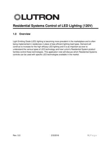
Figure 5a. Single and Multiple Heater Installations 120V ControlGTBK120V 60Hz 1 PhSupply circuit120V Thermostat110VThermostatOther burnersBurner 1WBKGNDL2L1 (HOT)WKEY:G-GREENW-WHITEBK-BLACKBKGother burnersFigure 5b. Single Heater Installations 24V ControlBKL1RINDMETHOD:Cut and strip pink cables linking terminals W1 and RAttach thermostat wires using suitable wire nuts.RMVPS1PS0YCYW1KW1Gas ControlXTRKEY:BL - BLUEBK - BLACKBR - BROWNGR - GREYK - PINKR - REDY - YELLOWKRBRX24V ThermostatGRCCOMBLFigure 5c. Multiple Heater Installations 24V DL2L1 (HOT)120V 60Hz 1 PhSupply circuitOther burnersBurner 124V ThermostatFan center relayKEY:G - GREENW - WHITEBK - BLACKR - REDW(Suppled by others)BKother burners
Figure 6. Internal Burner Wiring Diagram.GE120V AC Fan120V/60Hz ACSupplyKEY:BL - BLUEBK - BLACKBR - BROWNGR - GREYG - GREENK - PINKR - REDW - WHITEY - YELLOWWGNWBLBKG120v/24VAC 60HzYBRYWRGBKLPressure SwitchPower ON s ControlMCEGas ValveBLGRBRKKYYRRBKBurner ON (amber)NOTES:Power On light is permanently illuminated when 120V / 60 Hz AC external supply is connectedto burner.Additional wiring is required to install an optional extra thermostat and / or time clock.If no thermostat is required then a jumper is fitted between terminals R and W1. In thisconfiguration the burner will continuously fire until the 120V power supply is disconnected.Wire specification:- 18 AWG (1.0mm²), Tri-rated, 105 CIf any of the original wire as supplied with the appliance must be replaced, it must be replacedwith wiring material having a temperature rating of at least 220 F/105 C9
1.6 Vent Requirements and Details1.6.1 Unvented unitsHeaters may be installed without a ventproviding the governing building codes are metand consideration is properly given topossibilities of condensation on cold surfaces.Installation shall meet therequirements when unvented: followingInternal volume of the heated room mustbe greater than 214cu.ft. per 100 BTU/HR of heaters installed.ORNatural or mechanical means shall beprovided to supply and exhaust at least 4CFM per 1000 BTU per hour input ofinstalled heaters.Combustion gasses shall not impinge oncombustible materials.Standard vent terminals must extend at least6” (152mm) from the wall and at least24” (609mm) from any combustible overhang.This protects the building material fromdegradation by the vent gasses.Vent joints should be sealed and securedaccording to the vent manufacturersinstructions. Should condensation occur thevent should be shortened or insulated.The terminal should be at least 3ft (0.91m) awayfrom any air intake to the building.If the heater is equipped with ducted combustionair, the vent terminal must be at least 3ft(0.91m) away from the air inlet and locatedhigher than the inlet.The vent terminal must be installed at a suitableheight above the ground to prevent blockage bysnow.1.6.2 Vertical venting1.7The heater can be installed with a vertical vent.Whenever the heater is installed in locationswhere airborne dust or other pollutants arepresent, a fresh air supply should be ducted tothe burner.All vent piping should be adequately supportedfrom the building structure and terminated withan approved terminal. The maximumrecommended vent length is 25ft (7.6m) witha maximum of two elbows. All connectionsshould be properly sealed. refer fig 7a1.6.3 Horizontal ventingIndividual units can be vented horizontallythrough side walls. Recommended terminalsare Part Numbers 111848 for 4” and 111850 for6”.Distances from adjacent public walkways,adjacent buildings, openable windows andbuilding openings, consistent with the NationalFuel Gas Code, ANSI Z223.1/NFPA 54 or theNatural Gas and Propane Installation Code,CSA B149.1.Maximum length of vent is 25ft (7.6m) with two- 90 elbows.Fresh Air IntakeA fresh air duct of 4”(101mm) dia. should beinstalled from the fresh air to the air intakeconnection on the fanhousing. A flexiblejointing piece should be installed at the fanconnection with hose clamps to facilitateexpansion and contraction.The maximum recommended length air duct is25ft (7.6m) and the maximum number of elbowsis two. The minimum length is 18” (456mm).The location of the fresh air duct inlet must bewhere it will receive dust free clean air. An inletcap with bird screen must be fitted at the inlet ofthe duct. If the duct inlet is located above theroof the underside of the inlet terminal must beat least 2ft (0.61m) above roof level and at least10” (254mm) above any projection on the roofwithin 7ft (2.1m) of the inlet. Intake pipe, fittingsand sealant are not furnished by themanufacturer. Refer fig 7c & d.Runs of 12ft (3.6m) or shorter can use4” (101mm) dia vent. Runs over 12ft (3.6m)should use 6” (152mm) vent pipe.Any portion of vent that passes through acombustible wall must be insulated, or use anapproved insulating thimble.10
Figure 7.a Vertical Venting.CODE APPROVED VENTTHROUGH ROOFROOFSEALAPPROVEDCAT III VENT PIPEALUMINUMSUPPLIED BY OTHERS4" (101mm) O.D. OR6" (152mm) O.D. FLUE12'-0" (3.66m)12'-0" (3.66m)(APPROXIMATEMAXIMUM DIMENSIONS)SEAL JOINTS WITHHIGH TEMPERATURE SILICONE4" (101mm) TO 6" (152mm) DIA.CATALUMINUMADAPTERIII ADAPTERREQUIRED ONLY FOR 6" (152mm) DIA. VENTEND OF RADIANT TUBEVENTADAPTORCAT III ELBOWVENTELBOWFigure 7.b Horizontal Venting.REFLECTORS U P P LIE D B Y O T H ER SENSUREALLS E A L JO INT SJOINTSW IT H AREH IG H T E MSEALEDPERATU R ES IL IC O N E6 " (1 52 m m )C O L L AR4" (1 01 m m ) T O 6" (1 52 m m ) APPROVEDD IA . A L U MCATIN U3MVENTA D APIPEPTERR E Q U IR E D O N LY F O R 6" (1 52 m m ) D IA . V E N T SC O U P LE RR EFLEC TORIN L E T W IT HB IR D S C R E E NW ALLEND OFR A D IA N TT U BEA L U M IN U M 4" (1 01 m m ) O .D . M A X IM U M LE N G T H 12 '-0 " (3 .66 m )A L U M IN U M 6" (1 52 m m ) O .D .M A X IM U M LE N G T H 25 '-0" (7.62 m )(P LU S A M A X IM U M O F 2 x 9 0 ELBOWSBENDS36" (914mm) MIN CENTERST E R M IN A LNOTE: The ventterminal should beinstalled so as to be inthe same atmosphericpressure zone as thecombustion air inlet ofthe applianceFigure 7.c Fresh Air Ducted Intake.ALUMINUM 4" (101mm) O.D. PIPEMAX LENGTH 25'-0" (7.62m) WITHWITH 2-90 TWO–LONG90 RADIUSELBOWSBENDSFigure 7.d Wall Terminal Intake Kit.4.25”4"(108mm)O.D FLEXIBLEFLEXIBLEDUCT(106mm) O.D.DUCTCLAMPS36" (914mm) MIN CENTERSTERMINALWALLINLET WITHBIRD SCREENBURNER6" (152mm)11SEAL JOINTS WITHSILICONE OR DUCT TAPE
1.8Technical Details - Table 5No of Injectors1Gas Connection½” N.P.TElectrical Supply120 volt 1 phase 60HzVent size (in)4” or 6” (101mm or 152mm)Unitary Fan Motor Details120 volt 1 phase 60HzCurrent RatingIgnitionElectronic Program Start up with Spark IgnitionNatural GasLP GasMin. HeaterLengthMax. HeaterLengthMin. HeaterLengthMax. HeaterLengthBTU/HrBTU/HrS ft (m)S ft (m)U ft (m)U ft (m)1860,00060,00020 (6.1)40 (12.1)20 (6.1)40 (12.1)2580,00080,00020 (6.1)40 (12.1)20 (6.1)40 (12.1)30100,000100,00030 (9.1)50 (15.2)40 (12.1)40 (12.1)38123,500125,00040 (12.1)60 (18.3)40 (12.1)60 (18.3)45150,000150,00040 (12.1)70 (21.3)40 (12.1)60 (18.3)50169,000169,00050 (15.2)80 (24.4)60 (18.3)80 (24.4)60200,000N/A50 (15.2)80 (24.4)60 (18.3)80 (24.4)Burner SizeALTITUDE CONVERSION KITS ARE AVAILABLE1.2A MAXNatural Gas 0-2000 ft (0-610m)LP Gas 0-2000 ft (0-610m)Burner OrificePlateInjectorInjectorPressureBurner OrificePlateInjectorInjectorPressurePart No.Part No.inches WCPart No.Part No.inches 462704103.5BurnerSizeNatural Gas 2001-4500 ft (611-1370m)N/ALP Gas 2001-4500 ft (611-1370m)CANADAONLY 10%DERATEBurner OrificePlateInjectorInjectorPressureBurner OrificePlateInjectorInjectorPressureBurner SizePart No.Part No.inches WCPart No.Part No.inches A
Natural GasCombustion FanDetailsBurnerSizeFan TypeLP GasPressureSwitchOrificePart No.Part No.Combustion FanDetailsFan BurnerHeadPart No.Part No.OrificePart No.1830All 387269937N/AU TubeStraight TubeModelU20U4018 25 U60U80S10S20S30S40S50 S60S7030 38 45 S8050 60* Tube Type MaterialCalcoat Mild SteelMin. Distance toBend ft (m)18TUBE 1REMAINDER10 (3.0)25TUBE 1REMAINDER10 (3.0)30TUBE 1REMAINDER15 (4.6)38TUBE 1REMAINDER20 (6.1)45TUBE 1REMAINDER20 (6.1)50TUBE 1 & 2REMAINDER25 (7.6)60*TUBE 1 & 2REMAINDER25 (7.6)ModelOptions * Not available on LP Gas1234567All standard units fitted with unvented vent, natural gas and aluminized steel reflectors.1 off 180 bend (U) or upto 2 off 90 bends (L) can be fitted at no less than 50% of the total heater length.4” (101mm) or 6” (152mm) vent terminal.Combustion air kit.Reflector end caps.Altitude conversion kit.Propane and propane altitude conversion kit.13
2. Assembly Instructions.PLEASE READ this section priorassembly to familiarize yourself withcomponents and tools you require atvarious stages of assembly. Carefully openpackaging and check the contents againstparts and check list.tothethethethePlease ensure that all packaging isdisposed of in a safe environmentallyfriendly way.For your own safety we recommend theuse of safety boots and leather facedgloves when handling sharp or heavy items. Theuse of protective eye wear is alsorecommended.The manufacturer reserves the right to alterspecifications without prior notice.2.1Tools Required.Suitable alternative tools may be used.The following tools and equipment are advisableto complete the tasks laid out in this PhillipsScrewdriverWrenchSet5/16”Drive3/16” (5mm)5/32” (4mm)AllenwrenchTapeMeasureAssembly Notes.2.2.3 BracketsPlease read these assembly notes inconjunction with the correct assemblydrawings (figs 9 to 19).There can be four types of brackets suppliedwith these heaters: 2.2.1 TubesType ‘H’ are suspension brackets withtube straps.Each heating unit has two types of emitter tube.For details of the tube types please refer to thetable (page 13 of this instruction manual).Identify and position tubes on saw horses. Foraesthetics it is advisable to position all tubeseams facing down. Position couplingfastener so that these cannot be seen frombeneath the heater."A"VIEW ON "A"Mark out the position of the bracket centersfrom the dimensions shown on the assemblers'drawings.Turbulators: Ensure that the correctturbulator or burner insert is fitted, as this couldvoid your warranty if they are incorrectly fittedor omitted when necessary.2.2.2 Turbulators (where fitted) Insert turbulator into correct tubeas indicated in the assemblydrawings.14Type ‘G’ are suspension brackets withno tube straps.
DO NOT OVERTIGHTEN.Moving between the four bolts, tighten eachensuring that equal pressure is applied to eachbolt in turn. Complete assembly by drilling andscrewing self tapping retention zip screws.Type ‘F’ are fixed reflector brackets.At this point raise the tube assembly intoposition and suspend from previouslyfixed chains (Working Load 100lb). Longertube assemblies may be raised in more thanone sub-assembly with final tube connectionmade in the air. It is recommended that theheater be suspended to slope slightly down-ward from the burner approximately 1” in 20feet, but not more than 2” total overall.2 x SCREWS TIGHTENED TO FIX REFLECTOR Type ‘S’ are sliding reflector brackets.2.2.5 Reflectors.After removing the protective plastic coating(if fitted), slip the reflectors through the hangerbrackets until they overlap each other.LEAVE 1/8" MIN. GAP TO ALLOW REFLECTOR TO SLIDESlip the suspension brackets onto the tubeassembly. The fixed suspension point ’H’shown on the drawings are adjacent to theburner and secures the first suspension bracketto the tube with a tube strap. All othersuspension brackets ’G’ shown on thedrawings, have floating suspension points.All reflectors must be positioned/attached to the brackets exactly asdetailed in the assembly drawings.The first and second reflector are fixed at thepoint F by a type F reflector support bracket andare held in place by tightening the fixing screws.Reflectors are fixed at point ’F’ with a reflectorsupport bracket and reflectors are held inposition with fixing screws. Fixed and slidingjoints alternate along the heater at the spacingsindicated on the individual heater assemblysheets.Each subsequent reflector mustOVERLAP the previous one as shownbelow and to a distance as indicated bytheir individual assembly sheets.Alternate fixings of further reflectors by type Sand type F reflector brackets and space asindicated by individual assembly sheets.2.2.4 CouplersThe couplers are used for joining radiant tubesand U or L bends.Reflector support bracket assembliesare fitted at each reflector joint, with theclamp screws adjusted so that reflectorsare fixed together.Slide the coupler over the tube ensuring thatthe screw stop has butted up to the tube ends.Using the 9/16” wrench to tighten the bolts.15
HFREFLECTORSFSBURNERASSEMBLYTypical usage of optional bend kits:Corner reflector90 BendElbowEnd CapsEnd Cap2.2.6 End Caps (optional)Corner reflectors(optional)Corner reflectorskitPosition an end cap beneath the reflectorprofile (where required) with the end capflanges facing inwards. Fasten to reflectorusing the four ’Z’ clips.16” crs2.2.7 Bend(s) (where fitted)The heater can be installed with 1 or 2 90 bends or a 180 U bend.End CapsSlide the bend into the open end of thecoupler ensuring that the screw stop has buttedup to the tube ends. Refer to 2.2.4 forfastening.U Bend15”2.2.8 Burner/Fan Assembly.2.2.9 Detailed Assembly DrawingsSlide the burner assembly onto the open tubeend, ensuring it is fully engaged. Secure withset screws.The following pages show the technicaldimensional details of the range of heaters.For the purpose of unvented applications, a 4”90 elbow should be used on the terminatingend of the radiant tube sections. This elbowshould be turned with the outlet facing eitherside.Connect Gas and Electrical suppliesdescribed in sections 1.4 and 1.5.Please note the heater type, length andreference number from the delivery/advice notebefore identifying the correct model drawing.as16
Bends must be fitted at a distance of atleast 50% of the total heat exchangere.g. for a 60ft long heater, the closest tothe burner a bend can be is 30ft.Figure . 8. Possible Heater OrientationsS20S30S40S50S60S70S80U20U40U60U80
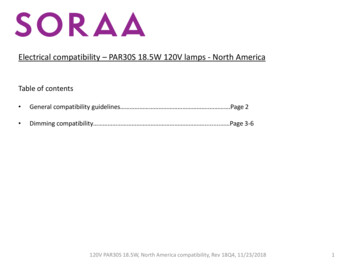
184"SUSPENSIONBRACKET12.6" ref6""A"VIEW ON G REFLECTOR BRACKETGFIXED REFLECTOR BRACKETSUPPLIEDNUT &BOLTREFLECTORDETAIL2 x SCREWS MIN 1/8" GAP TOALLOW REFLECTOR TO SLIDEHTURBULATOR DETAIL PT. NO. 270495STANDARD 4" COUPLERF6"-9" REFLECTOR OVERLAPNOTE: FOR MODELS 18/25 LP GAS ONLYCOUPLERS2 x SCREWS TIGHTEN TOFIX REFLECTORRADIANTTUBEDETAILBURNER INSERT(SEE DETAIL)MODEL 25NAT GAS ONLYGTUBE & REFLECTOR SUSPENSION BRACKETSWAGEDTUBE/TUBE ORIFICE270492 FITTEDBURNER ENDMODEL 12 ONLY10' 3" REFLECTORS TYPICAL OF 2DISTANCE BETWEENSUSPENSION POINTSNO TO EXCEED 12'FIRST SUSPENSION POINT TUBE STRAPRADIANTTUBESUPPLIEDNUT & BOLTBURNERENDCAPS(OPTIONAL)H21'6½" NOMINAL OVERALL ASSEMBLED LENGTH2" MINIMUMREFLECTOR 080,00060,00041,500NAT GAS LP GASBTU/HR BTU/HR18-S2012-S20MODEL NUMBERNOTE: FOR MODEL 80 NAT GAS ONLYBURNER INSERT DETAIL PT. NO. 270489TURBULATOR(SEE DETAIL)MODEL 12 AND 18LP GAS ONLYGFigure 9. Heater Assembly: Model Linear 18-S20 and 25-S20.
4"12.6" ref6"19"A"VIEW ON G REFLECTOR BRACKETGFIXED REFLECTOR BRACKETSUPPLIEDNUT &BOLTREFLECTORDETAIL2 x SCREWS MIN 1/8" GAP TOALLOW REFLECTOR TO SLIDEH2 x SCREWS TIGHTEN TOFIX REFLECTORRADIANTTUBEDETAILBURNER INSERTSEE DETAILMODEL 25 ANDMODEL 30NAT GAS ONLYGFTUBE & REFLECTOR SUSPENSION BRACKETSWAGEDTUBE/TUBE ORIFICE270492 FITTEDBURNER ENDMODEL 12 ONLY10' 3" REFLECTORS TYPICAL OF 3DISTANCE BETWEENBETWEENSUSPENSION POINTSSUSPENSIONPOINTSNO TO EXCEEDEXCEED 12'12’FIRST SUSPENSION POINT TUBE STRAPRADIANTTUBESUPPLIEDNUT & ARD 4" COUPLERCOUPLERS6" REFLECTOR OVERLAPG31'6½" NOMINAL OVERALL ASSEMBLED LENGTH2" MINIMUMREFLECTOR -S3060,00041,50080,00060,00025-S3041,50018-S30NAT GAS LP GASBTU/HR BTU/HR12-S30MODEL NUMBERNOTE: FOR MODELS 25/30 NAT GAS ONLYBURNER INSERT DETAIL PT. NO. 2704896" REFLECTOR OVERLAPGFigure 10. Heater Assembly: Model Linear 18-S30, 25-S30 and 30-S30.
IDING REFLECTOR BRACKETGFIXED REFLECTOR BRACKETSUPPLIEDNUT &BOLTREFLECTORDETAILTUBE & REFLECTOR SUSPENSION BRACKET2 x SCREWS MIN 1/8" GAP TOALLOW REFLECTOR TO SLIDEH6" REFLECTOROVERLAP2 x SCREWS TIGHTEN TOFIX REFLECTORRADIANTTUBEDETAILGBURNER INSERTNAT GAS ONLYSEE DETAILFCOUPLER*(HIGH TEMP COUPLERMODELS 38/45)VIEW ON "A"4"10' 3" REFLECTORSTYPICAL OF 4DISTANCE BETWEENSUSPENSION POINTSNO TO EXCEED 12'FIRST SUSPENSION POINT TUBE STRAPRADIANTTUBESUPPLIEDNUT & BOLTSUSPENSIONBRACKETBURNERENDCAPS(OPTIONAL)HS6" REFLECTOROVERLAP* HIGH TEMP 4" COUPLERSTANDARD 4" COUPLERG41'6½" NOMINAL OVERALL ASSEMBLED 0,00060,00025-S40NAT GAS LP GASBTU/HR BTU/HR18-S40MODEL NUMBERNOTE: FOR MODELS 25/30 NAT GAS ONLYBURNER INSERT DETAIL PT. NO. 2704893" REFLECTOROVERLAP2" MINIMUMFREFLECTOR OVERLAPCLGFigure 11. Heater Assembly: Model Linear 18-S40, 25-S40, 30-S40, 38-S40 and 45-S40.
21"A"TUBESTRAPTUBESTRAPDETAILFDETAILSSLIDING REFLECTOR BRACKETGFIXED REFLECTOR BRACKETSUPPLIEDNUT &BOLTREFLECTORDETAIL2 x SCREWS MIN 1/8" GAP TOALLOW REFLECTOR TO SLIDEH2 x SCREWS TIGHTEN TOFIX REFLECTORRADIANTTUBEDETAILFCOUPLER(HT COUPLERMODELS 50 & 60)6" REFLECTOROVERLAPGTUBE & REFLECTOR SUSPENSION BRACKET* HT COUPLERON MODELS 38,45, 50 & 60BURNER INSERTSEE DETAILREFLECTORVIEW ON "A"6"4"10' 3" REFLECTORSTYPICAL OF 5DISTANCE BETWEEN GSUSPENSIONPOINTS NOT TOEXCEED 12'FIRST SUSPENSION POINT TUBE STRAPRADIANTTUBESUPPLIEDNUT & BOLTSUSPENSIONBRACKETBURNERENDCAPS(OPTIONAL)H* HIGH TEMP 4" COUPLERSTANDARD 4" COUPLERS6" 38-S50169,000100,000100,00030-S50*50-S50NAT GAS LP GASBTU/HR BTU/HRMODEL NUMBERNOTE: FOR MODEL 30 NAT GAS ONLYBURNER INSERT DETAIL PT. NO. 2704893" REFLECTOROVERLAP2" MINIMUMGREFLECTOR OVERLAP3" REFLECTORO
INSTALLATION / OPERATION / MAINTENANCE Applies to: Model VP1 120V 60Hz Gas-Fired, Tubular, Radiant, Low-Intensity Infrared Heater Part No. 270683 . . * Connector must be certified for use on a radiant tube type infrared heater and must comply with Standard for Connectors for Gas Appliances, ANSI Z21.24/CSA 6.10 or .