Transcription
Detroit Radiant Products Co.Tube HeaterGeneral ManualTo be used in conjunction with Series 2 insert manuals.!!WARNINGImproper installation, adjustment, alteration, service or maintenance can causeproperty damage, injury or death. Read and understand the installation, operating andmaintenance instructions thoroughly before installing or servicing this equipment.This heater must be installed and serviced by trained gas installation and servicepersonnel only. Failure to comply could result in personal injury, asphyxiation, death,fire and/or property damage.In locations used for the storage of combustible materials, signs must be posted tospecify the maximum permissible stacking height to maintain the required clearancesfrom the heater to the combustibles. Signs must either be posted adjacent to theheater thermostats or in the absence of such thermostats, in a conspicuous location.For Your SafetyIf you smell gas: Do not try to light any appliance. Immediately call your gas supplier from a neighbor’s phone. Do not touch any electrical switch. Follow the gas supplier’s instructions. Do not use any phone in your building. If you cannot reach your gas supplier, call the fire department.INSTALLER: Present this manual to the end user.Keep these instructions in a clean and dry place for future reference.Model#: Serial #:(located on rating label)LIOGTa-Rev. 25711Print: 5M-01/16 r1-04/16 (CDS)Replaces: LIOGTa-5M-01/14 (CDS)
Tube Heater General ManualContents1.0 Introduction . . . . . . . . . . . . . . . . . . . . . . . . . . . . . . . . . . . . . . . . . . . . . . . . . . . . . . . . . . . . . . 3Overview . . . . . . . . . . . . . . . . . . . . . . . . . . . . . . . . . . . . . . . . . . . . . . . . . . . . . . . . . . . . . 3Heater Components . . . . . . . . . . . . . . . . . . . . . . . . . . . . . . . . . . . . . . . . . . . . . . . . . . . 32.0 Safety . . . . . . . . . . . . . . . . . . . . . . . . . . . . . . . . . . . . . . . . . . . . . . . . . . . . . . . . . . . . . . . . . . . 4Warning Symbols . . . . . . . . . . . . . . . . . . . . . . . . . . . . . . . . . . . . . . . . . . . . . . . . . . . . . 4Applications . . . . . . . . . . . . . . . . . . . . . . . . . . . . . . . . . . . . . . . . . . . . . . . . . . . . . . . . . . 4Clearance to Combustibles . . . . . . . . . . . . . . . . . . . . . . . . . . . . . . . . . . . . . . . . . . . . . . 5Safety Signs and Labels . . . . . . . . . . . . . . . . . . . . . . . . . . . . . . . . . . . . . . . . . . . . . . . . . 5Venting . . . . . . . . . . . . . . . . . . . . . . . . . . . . . . . . . . . . . . . . . . . . . . . . . . . . . . . . . . . . . . 6Gas Supply . . . . . . . . . . . . . . . . . . . . . . . . . . . . . . . . . . . . . . . . . . . . . . . . . . . . . . . . . . 6Heater Expansion . . . . . . . . . . . . . . . . . . . . . . . . . . . . . . . . . . . . . . . . . . . . . . . . . . . . . 6Standards, Certifications and Government Regulations . . . . . . . . . . . . . . . . . . . . . . . . 73.0 Installation . . . . . . . . . . . . . . . . . . . . . . . . . . . . . . . . . . . . . . . . . . . . . . . . . . . . . . . . . . . . . . . 9Design Considerations and Prechecks . . . . . . . . . . . . . . . . . . . . . . . . . . . . . . . . . . . . . 9Hanger Placement and Suspension . . . . . . . . . . . . . . . . . . . . . . . . . . . . . . . . . . . . . . . 12Radiant Tube Assembly . . . . . . . . . . . . . . . . . . . . . . . . . . . . . . . . . . . . . . . . . . . . . . . . . 16Optional Elbow or U-Bend Accessory Configuration . . . . . . . . . . . . . . . . . . . . . . . . . . 17Burner Control Box Suspension . . . . . . . . . . . . . . . . . . . . . . . . . . . . . . . . . . . . . . . . . . 19Reflector Assembly . . . . . . . . . . . . . . . . . . . . . . . . . . . . . . . . . . . . . . . . . . . . . . . . . . . . 20Baffle Assembly and Placement . . . . . . . . . . . . . . . . . . . . . . . . . . . . . . . . . . . . . . . . . . 22Final Heater Assembly . . . . . . . . . . . . . . . . . . . . . . . . . . . . . . . . . . . . . . . . . . . . . . . . . 23Venting . . . . . . . . . . . . . . . . . . . . . . . . . . . . . . . . . . . . . . . . . . . . . . . . . . . . . . . . . . . . . 24Sidewall (Horizontal) Venting . . . . . . . . . . . . . . . . . . . . . . . . . . . . . . . . . . . . . . . . . . . . . 25Roof (Vertical) Venting . . . . . . . . . . . . . . . . . . . . . . . . . . . . . . . . . . . . . . . . . . . . . . . . . . 26Optional Unvented Operation . . . . . . . . . . . . . . . . . . . . . . . . . . . . . . . . . . . . . . . . . . . . . 28Combustion Air Requirements . . . . . . . . . . . . . . . . . . . . . . . . . . . . . . . . . . . . . . . . . . . 28Gas Supply . . . . . . . . . . . . . . . . . . . . . . . . . . . . . . . . . . . . . . . . . . . . . . . . . . . . . . . . . . 304.0 Operation . . . . . . . . . . . . . . . . . . . . . . . . . . . . . . . . . . . . . . . . . . . . . . . . . . . . . . . . . . . . . . . . . 335.0 Maintenance . . . . . . . . . . . . . . . . . . . . . . . . . . . . . . . . . . . . . . . . . . . . . . . . . . . . . . . . . . . . . . 34Troubleshooting Guide . . . . . . . . . . . . . . . . . . . . . . . . . . . . . . . . . . . . . . . . . . . . . . . . . 356.0 Limited Warranty . . . . . . . . . . . . . . . . . . . . . . . . . . . . . . . . . . . . . . . . . . . . . . . . . . . . . . . . . . 362
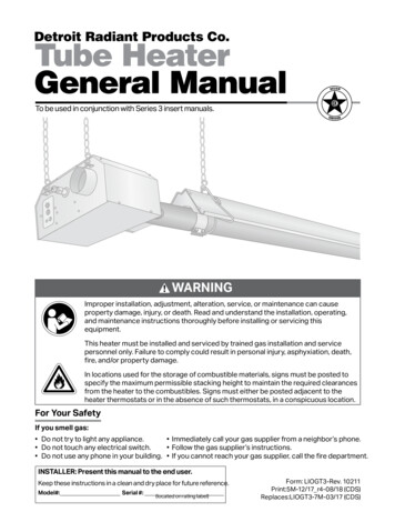
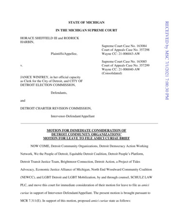
1.0 Introduction Overview Heater ComponentsTube Heater General Manual1.0 IntroductionOverviewThe intent of this manual is to provide information regarding general safety, installation, operation andmaintenance of the tube heater. For complete assembly and installation instructions, use this Tube HeaterGeneral Manual in conjunction with the Series Insert Manual that accompanies this piece. You must read,and understand, the instructions and safety warnings in both manuals before installing the tube heater.Heater Components*Prior to installation, verify that the heater’s gas type and voltage (as listed on the rating plate) match that ofyour application. Also verify that you have received all heater contents included with your tube heater. Referto the Series Insert Manual for a list of the kit contents for your Series heater. Materials not included in theheater kit contents (e.g., screws, vent material, terminals, etc.) are the responsibility of the installer. Notifyyour product representative or Detroit Radiant Products of any discrepancy or missing kit contents prior toinstalling unit.Figure 1.1 Heater Components *Tube HangerChains are not provided in kit.Optional accessory. P/N: THCSReflector10’ )Reflector Center SupportReflectorTensionSpring*Tube HangerReflector End Cap with Clips*Burner Control BoxBaffles16” Burner TubeTube ClampIgniter/Sensor BoxShut-off Valve*Flexible Gas Connector** Not all items illustrated may be provided with your heater.Refer to kit contents on page 20 of the Series Insert Manual.3
2.0 Safety Warning Symbols ApplicationsTube Heater General Manual2.0 Safety!!WARNINGImproper installation, adjustment, alteration, service or maintenance can causeproperty damage, serious injury or death. Read and understand, the installation,operating and maintenance instructions thoroughly before installing or servicing thisequipment. Only trained, qualified gas installation and service personnel may install orservice this equipment.Warning SymbolsSafety is the most important consideration during installation, operation and maintenance of the tubeheater. You will see the following symbols and signal words when there is a hazard related to safety orproperty damage.!!WARNINGWarning indicates a potentially hazardous situationwhich, if not avoided, could result in death or injury.CAUTIONCaution indicates a potentially hazardous situationwhich, if not avoided, could result in minor ormoderate injury.NOTICENotice indicates a potentially hazardous situationwhich, if not avoided, could result in propertydamage.ApplicationsThis is not an explosion proof heater. No tube heater may be used in a Class 1 or Class 2 ExplosiveEnvironment. Consult your local fire Marshall, insurance carrier and other authorities for approval if the!proposed installation is in question.Commercial / IndustrialUnless otherwise indicated, tube heaters are designed and certified for use in industrial and commercialbuildings, such as warehouses, manufacturing plants, aircraft hangars and vehicle maintenance shops.For maximum safety the building must be evaluated for potential problems before installing the heatingsystem. A critical safety factor to consider before installation is the clearance to combustibles.!WARNINGNot For Residential Use. Installation of a commercial tube heater system in residential indoor spacesmay result in property damage, serious injury or death.4
2.0 Safety Clearance to Combustibles Safety Signs and LabelsTube Heater General ManualClearance to Combustibles!WARNINGPlacement of explosive objects, flammable objects, liquids and vaporsclose to the heater may result in explosion, fire, property damage, seriousinjury or death. Do not store or use explosive objects, liquids and vapor inthe vicinity the heater.Hazards:For maximum safety the building must be evaluated for hazards before installing the heating system.Examples include, but are not limited to: Gas and electrical linesCombustible and explosive materialsChemical storage areasAreas of high chemical fume concentrationsProvisions for accessibility to the heaterAdequate clearances around air openingsCombustion and ventilating air supply Vehicle parking areasVehicles with lifts or cranesStorage areas with stacked materialsLightsSprinkler headsOverhead doors and tracksDirty, contaminated environmentA critical safety factor to consider before installation is the clearances to combustibles. Clearance tocombustibles is defined as the minimum distance you must have between the tube surface, or reflector,and the combustible item. Considerations must also be made for moving objects around the tube heater.The following is a partial list of items to maintain clearances from:Combustible items:Moving Objects: WoodPaperFabricChemicals PaintParked vehiclesGasolineStorage racksOverhead doorsVehicle liftsCranesHoistsWhen installing the tube heating system, the minimum clearances to combustibles for your Series tubeheater and system configuration must be maintained. These distances are shown in your Series InsertManual and on the burner control box. If you are unsure of the potential hazards, consult your local fireMarshall, fire insurance carrier or other qualified authorities on the installation of gas fired tube heaters forapproval of the proposed installation.Safety Signs and LabelsIt is important to provide warnings to alert individuals to potential hazards and safety actions. ANSIZ83.20b and CSA 2.34 require you to post a sign “specifying the maximum permissible stacking height tomaintain the required clearances from the heater to the combustibles” near the heaters thermostat or inabsence of such thermostats in a conspicuous location. Contact Detroit Radiant Products Co. or anauthorized dealer for Clearance Safety Limit Signs or for Clearance Safety Limit Tags (one tag is providedwith each heater).Safety warning labels must be maintained on the tube heater. Illustrations of the safety labels, and theirlocations, are pictured in the Series Insert Manual. In locations used for the storage of combustiblematerials, signs must be posted to specify the maximum permissible stacking height to maintain therequired clearances from the heater to combustibles. Signs must either be posted adjacent to the heaterthermostats or in the absence of such thermostats in a conspicuous location.5
2.0 Safety Venting Gas Supply Heat ExpansionTube Heater General ManualVentingWARNING!Insufficient ventilation may result in health problems, carbon monoxide poisoning and death.Vent enclosed spaces and buildings according to national, state, provincial and local codes.!This tube heater must be vented in accordance with national, state, provincial and local codes and theguidelines in the Detroit Radiant Tube Heater General Manual (refer to pages 24-28) and applicableSeries Insert Manual. In the United States refer to the latest edition of the ANSI Z223.1 (NFPA 54)Standard and in Canada refer to the latest edition of the CAN/CGA B149.2 Standard.Gas SupplyWARNING!Improperly connected gas lines may result in serious injury and death,explosion, poisonous fumes, toxic gases or asphyxiation. Connect gas lines inaccordance to national, state, provincial and local codes.!The gas supply to the tube heater must be connected and tested in accordance with national, state,provincial and local codes along with the guidelines in the Detroit Radiant General (refer to pages 31 - 32)and the Series Insert Manual. In the United States refer to the latest edition of the ANSI Z223.1 (NFPA 54)Standard and in Canada refer to the latest edition of the CAN/CGA B149.2 Standard.Heater Expansion!WARNINGAllowances must be made for the system to expand. Improper installation, adjustment,alteration, service or maintenance can cause property damage, injury or death.A flexible gas connection of approved type is required. Connectors must be installed in oneplane and without sharp bends, kinks or twists.The tube heater expands and contracts during operation. Follow the installation instructions to ensureallowances are made for this movement. To ensure your safety, and comply with the terms of the warranty,all units must be installed in accordance with these instructions.6
Tube Heater General Manual2.0 Safety Standards, Certifications and Government RegulationsStandards, Certifications and Government RegulationsInstallation of this tube heater must comply with all applicable local, state and national specifications,regulations and building codes. Contact the local building inspector and/or fire marshall for guidance.In the absence of local codes, the installation must conform to the latest edition of:United States: National Fuel Gas Code, ANSI Z223.1 (NFPA 54).Canada: CAN/CGA B149.1 and .2, Canadian Electrical Code C22.1Chart 2.1 Standards and Code Installation Guidelines Building TypeBuildingTypePublicGaragesCodes and GuidelinesInstallation of this tube heater in public garages must conform to the following codes:United States: Standard for Parking Structures NFPA 88A (latest edition) or theCode for Motor Fuel Dispensing Facilities and Repair GaragesNFPA 30A (latest edition).Canada: Refer to CAN/CGA B149.1: Installation Codes for Gas Burning Appliancesand applicable Standards for Public Garages.Guidelines: Heaters must not be installed less than 8 ft. (2.4 m) above the floor. Minimumclearances to combustibles must be maintained from vehicles parked below theheater. When installed over hoists, minimum clearances to combustibles must bemaintained from the upper most point of objects on the hoist.AircraftHangarsInstallation of this tube heater in aircraft hangars must be in accordance with thefollowing codes:United States: Refer to Standard for Aircraft Hangars, ANSI/NFPA 409(latest edition).In Canada: Refer to Standard CAN/CGA B149.1 and applicable Standards forAircraft Hangars.Guidelines: In aircraft storage and servicing areas, heaters shall be installed at least 10 ft. (3 m)from above the upper surface of wings or of the engine enclosures of the highestaircraft that may be housed in the hangar. The measurement shall be made fromthe wing or engine enclosure, whichever is higher from the floor, to the bottom ofthe heater. In areas adjoining the aircraft storage area (e.g., shops, offices) the bottom ofheaters shall be installed no less than 8 ft. (2.4 m) above the floor. Suspended or elevated heaters shall be located in spaces where they shall not besubject to damage by aircraft, cranes, movable scaffolding or other objects.Provisions shall be made to assure accessibility to suspended tube heaters for recurrentmaintenance purposes.7
2.0 Safety Standards, Certifications and Government RegulationsTube Heater General ManualChart 2.2 Standards and Code Installation Guidelines Building elinesInstallation of this tube heater is approved, without modifications, for elevations up to6,000 feet (1,829 m) MSL (sea level) in the United States. Contact the factory forinstallations above these elevations.The type of gas appearing on the nameplate must be the type of gas used. Installationmust comply with national and local codes and requirements of the local gas company.NonStandardBTU GasGuidelines:Unless otherwise noted on the rating plate, this infrared heater is designed and orificed tooperate on standard BTU gas. Contact the factory if utilizing non-standard BTU gas.Chart 2.3 Standards and Code Installation Guidelines Building AspectBuildingAspectElectricalCodes and GuidelinesThe tube heater must be electrically grounded in accordance with the following codes:United States: Refer to National Electrical Code , ANSI/NFPA 70 (latest edition).Wiring must conform to the latest edition of National ElectricalCode , local ordinances, and any special diagrams furnished.Canada: Refer to Canadian Electrical Code CSA C22.1 Part 1 (latestedition).VentingVenting must be installed in accordance with the requirements within this manual and thefollowing codes:United States: Refer to NFPA 54/ANSI Z223.1 (latest edition), National FuelGas Code.Canada: Refer to CAN/CGA B149.1 Installation Codes for Gas BurningAppliances.Applicable authorities governing the manufacturing or installation of this infrared heater include(but are not limited to) the following organizations: NFPA - National Fire Protection Association. AGA - American Gas Association. ANSI Z83.20b - American National Standards Institute. CSA - Canadian Standards Association. NFPA 54/ANSI Z223.1 - National Fuel Gas Code. CE - Certification of Europe. OSHA - Occupational Safety & Health Administration. IRSC - Infrared Heater Safety Council. IAS - International Approval Services.NOTE: Refer to the Series Insert Manual for model specific certifications and approvals.8
3.0 Installation Design Considerations and PrechecksTube Heater General Manual3.0 Installation!WARNINGImproper installation, adjustment, alteration, service or maintenance can cause propertydamage, serious injury or death.Read and understand, the installation, operating and maintenance instructionsthoroughly before installing or servicing this equipment.Only trained, qualified gas installation and service personnel may install or service thisequipment.Design Considerations and PrechecksPlacement of infrared heaters is influenced by many factors. Aside from safety factors, considerationssuch as the number of heater or vent elbows that are allowed, maximum vent lengths, ducting ofcombustion air and combining exhaust vents are a few examples. All installation manuals, along withnational, state, provincial and local codes, address these issues. It is critical that you read, understandand follow all guidelines and instructions.To ensure a properly designed heating system, a layout should be developed for the correct placement ofthe burner control box, tubes, vents and combustion air intake ducts. Inspect and evaluate the mountingconditions, vent locations, gas supply and wiring.When designing an infrared radiant heating system, consider the following: Has the building’s heat loss been evaluated? Does the design meet the needs of the space? Have recommended mounting heights been observed? Have all clearance to combustibles situations been observed? Is the supply (burner) end of the heater located where more heat is required? Is it best to offset the heaters and/or rotate the reflectors towards the heat zone? Are extra guards, side shields, ‘U’ or ‘L’ reflector covers required? Does the heater require outside fresh air for combustion? Is the environment harsh or contaminated (requiring outside air for combustion)? Are chemicals or vapors a concern (requiring outside air for combustion or additional ventilation)?The effective infrared surface temperature of a person or object may be diminished with wind above 5mph. The use of adequate wind barrier(s) may be required.IMPORTANT: Fire sprinkler heads must be located at an appropriate distance from the heater. Thisdistance may exceed the published clearance to combustibles as posted on the heater. Certainapplications may require the use of high temperature sprinkler heads or the relocation of the heaters.Sprinkler systems containing propylene glycol or other flammable substances are not to be used inconjunction with this heater without careful consideration for and avoidance of potential fire hazards. Forfurther information, consult NFPA 13.9
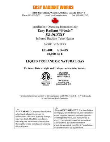
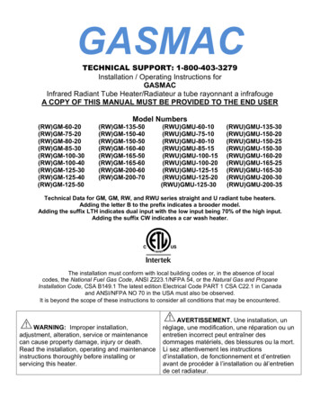
3.0 Installation Design ConsiderationsTube Heater General ManualWhen heated, materials high in hydrocarbons (solvents, paint thinner, mineral spirits, formaldehydes, etc.)can evaporate. This may result in odors or fumes being emitted into the environment. To correct thisproblem, clean the area and/or introduce additional ventilation. The heaters themselves, when installedand serviced in accordance with the installation manual, do not emit foul odors into the environment.Design Scenario:A tube heater system is being installed in a 90’ (L) x 50’ (W) x 14’ (H) space. Two overhead doors are locatedat one end and an equipment storage area on one side. The calculated heat load is 400,000 BTU/h.Figure 3.1 Poor Design90’Gas Supply80’ - 200,000 BTU(2 total)Doors andtracksEquipment storageToo HotToo ColdDoors andtracks50’Poor Design Two burners (200,000 BTU each) are placed at one end, opposite the area of highest demand(e.g., overhead doors). Recommended mounting heights are not observed (see Chart 3.1). Produces an uneven heat distribution.Figure 3.2 Good Design90’Gas Supply40’ - 100,000 BTU(4 total)Doors andtracksEquipment storageBetter Heat DistributionDoors andtracks50’Good DesignSidewall Vent (2 total) Four burners (100,000 BTU each) are placed in each corner. Burner (hotter) ends direct heat to areas ofhighest heat demand. Recommended mounting heights have been observed. Distributes heat more evenly.10
3.0 Installation Mounting Heights and CoveragesTube Heater General ManualChart 3.1 Recommended Mounting Heights and CoveragesCoverage AreaStraight Config.(LxW)Coverage AreaU-Tube Config.(LxW)Distance BetweenHeaters (ft.)Dimension ADistance BetweenHeater Rows (ft.)Dimension BMaximum DistanceBetween Heaters andwall (ft.) DimensionC10’ - 16’20’ x 12’12’ x 12’10’ - 20’20’ - 40’16’75-100 MBH12’ - 20’22’ x 15’N/A20’ - 30’30’ - 50’18’50-65 MBH10’ - 16’30’ x 14’17’ x 13’10’ - 20’20’ - 40’17’75-125 MBH12’ - 20’33’ x 18’18’ x 15’20’ - 30’30’ - 50’20’50-65 MBH10’ - 16’40’ x 16’22’ x 14’10’ - 20’20’ - 40’20’75-125 MBH12’ - 20’44’ x 21’23’ x 17’20’ - 30’30’ - 50’20’150-175 MBH16’ - 30’45’ x 26’24’ x 20’30’ - 40’40’ - 60’25’100-125 MBH15’ - 25’55’ x 24’28’ x 19’20’ - 30’30’ - 50’25’150-200 MBH16’ - 30’56’ x 30’29’ x 23’30’ - 40’40’ - 60’25’125 MBH16’ - 25’66’ x 27’33’ x 21’20’ - 30’30’ - 50’25’150-200 MBH17’ - 40’67’ x 34’34’ x 26’30’ - 40’40’ - 60’25’70 ft.175-200 MBH17’ - 40’78’ x 38’39’ x 29’30’ - 40’40’ - 60’30’80 ft.200 MBH18’ - 45’89’ x 42’44’ x 32’30’ - 40’40’ - 60’30’20 ft.30 ft.40 ft.50 ft.60 ft.BTU Range50-65 MBHModelRecommendedMounting Height (ft.)Note: This chart is provided as a guideline. Actual conditions may dictate variation from this data.Factory recommended mounting heights are listed as a guideline. If infrared heaters are mounted too lowor too high, they may result in discomfort or lack of heat. Detroit Radiant Products Company generallyrecommends observing the recommended mounting heights to optimize comfort conditions. However,certain applications such as spot heating, freeze protection, outdoor patio heating or very high ceilingsmay result in the heaters being mounted outside of the factory recommended mounting heights.Figure 3.3 Mounting Height Dimensions (see Chart 3.1 for dimensions)Dimension ADimension BDistance betweenheater rowsDimension ADimension CMaximumdistancebetweenheaterand wallDimension CMaximum distance between heater and wallNote: Dimensions A, B & C are based upon heaters hung at the factory recommended mounting height.11
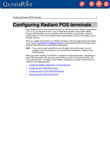
3.0 Installation Hanger Placement and SuspensionTube Heater General ManualHanger Placement and Suspension!WARNINGImproper suspension of the tube heater may result in collapse and being crushed. Alwayssuspend from a permanent part of the building structure that can evenly support the totalforce and weight of the heater.Failure to maintain minimum clearance to combustibles may result in fire and/or explosion,property damage, serious injury or death. Always maintain minimum clearances and postclearance safety limit signs or the clearance safety tag where needed.Suspension of the heater must conform to applicable codes referenced in the Safety section andthese instructions.1Lay all radiant tubing out in the following order. Position tubes in approximate location (see figure 3.4). 10 ft. primary combustion chamber. If applicable, the secondary 10 ft. aluminized treated steel combustion chamber (150-200 MBHmodels only). Refer to the Specifications Chart in the Series Insert Manual to determine if a secondcombustion chamber is required for your model heater. Radiant emitter tubes.Important! 150,000-200,000 BTU/h models must use the 10 ft. titanium alloy treated combustionchamber as the first tube downstream of the burner control box. The combustion chamber hasan orange identification sticker located on the swaged end of the tube.Stainless Steel Heaters must use the 409 Series stainless steel combustion chamber as thefirst tube downstream of the burner control box.2 Mark locations for hanging points.NOTE: If the available hanging points do not allow for the recommended spacing then additionalhangers (P/N: TP-19B) may be necessary. The spacing between the burner control box mounting brackets and the first hanger should beapproximately 2’-4”. The space between the first two hangers placed on the first tube, should be approximately 8’-10”. The space between hangers thereafter, one per tube, should be approximately 9’-8”.12
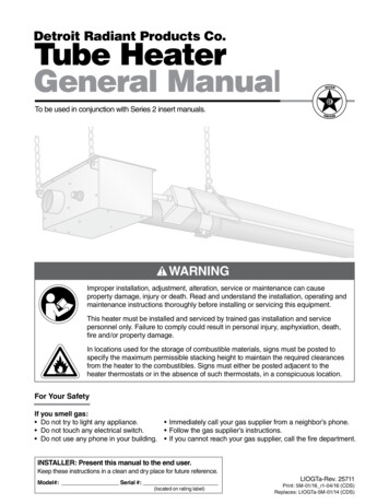
3.0 Installation Hanger Placement and SuspensionTube Heater General ManualFigure 3.4 Heater Mounting LayoutSuspension PointNOTE: A sticker identifying thecombustion chamber(s) is located onthe swaged end of the tube(s).89’SuspensionPoint89’””Radiant EmitterTube(s)SuspensionPointBurner Control BoxSuspension Points2’Radiant Emitter TubeNOTE: If applicable use a SecondaryCombustion Chamber. Refer to theSpecifications Chart in the SeriesInsert Manual.”108’4”Stainless Steel Tube Clamp(150-200 MBH models only)16” BurnerTube10 ft. Primary Combustion ChamberNOTE: Type varies depending onmodel, refer to the SpecificationChart in the Series Insert Manual.Igniter/Sensor BoxBurner Control BoxModelDimension*Straight ConfigurationSuspension PointsControl Box StabilizerShipping WeightStainless Steel ShipWeightChain Set Qty.StraightChain Set Qty.w/TF1BOptional BrassKnuckle (P/N:BK)Optional SingleMount BracketChart 3.2 Heater Mounting Requirements and Weights20 ft.21’-8” / 260”32120 lbs.145 lbs.563230 ft.31’-4” / 376”42160 lbs.195 lbs.6843**40 ft.41’-0” / 492”52190 lbs.235 lbs.785350 ft.50’-8” / 608”62235 lbs.290 lbs.81064**60 ft.60’-4” / 724”72265 lbs.330 lbs.9107470 ft.70’-0” / 840”82300 lbs.375 lbs.101285**80 ft.79’-8” / 956”92330 lbs.405 lbs.111295* Refer to page 18 for U-bend configuration dimensions.** Model requires 5EA-SUB accessory package when installing in a U-shaped configuration.13
3.0 Installation Hanger Placement and SuspensionTube Heater General Manual3 Prepare mounting surface, if necessary weld blocks, drill holes (see figure 3.5).NOTE: The burner control box and radiant tubes should be in straight alignment and level.4 Fasten beam clamp, screw hook or other type of suspension anchor to hanging point.5Attach and close S-hook (P/N: S-HOOK) and #1 double-loop chain (P/N: THCS) to anchor. Checkthat it is securely attached. NOTE: Threaded rod and turnbuckles may be used.6 Attach hangers to chains. Adjust chain lengths until radiant tubing is level and equal weight distributionis achieved. Chains must be straight up and down. Do not install chains at an angle as this can resultin tube warping or separation.Figure 3.5 Mounting the Hangers3 I-Beam3 I-Beam4 Beam Clamp4 Beam Clamp6 Threaded Rod5 S-Hook and #1Double-Loop Chain5 Threaded Rodand Turnbuckle6 Chain3 Concrete Beam3 Wood Beam4 Screw Hook4Screw Hookwith Locknutand Washer6 Chain6 Chain14
3.0 Installation Hanger Placement and SuspensionTube Heater General ManualFigure 3.6 U-Tube Hanger Mounting OptionsSingle MountingBracketBrass KnuckleExhaustEndU-Tubes can be mounted from a single suspensionpoint using a Single Mounting Bracket (P/N: SMB)with five S-hooks and #1 double-loop chains.U-Tubes can be mounted at a15, 30 or 45 degree angle with twosuspension points, using two Brass Knuckle(P/N: BK) fittings, #1 double-loop chains and S-hooks.Figure 3.7 Angled Hanger Mounting Options45 30 For 45 degree hanging angle use twoS-hooks and two #1 double-loop chains.1515 For variety of hanging angles, use the BrassKnuckle (P/N: BK) fitting with a #1 doubleloop chain and S-hook.
3.0 Installation Radiant Tube AssemblyTube Heater General ManualRadiant Tube AssemblyTo install the radiant tubes:1Place tubes in hangers with the welded seam facing downward and the swaged end of the tubetowards the exhaust end of the heater system (see figure 3.8).Refer to the Series Insert Manual for tube installation sequence.Figure 3.8 Attach HangersSwaged EndRadiant TubeHangerWelded seamfaces down2Slide tube clamps onto radiant tubes
This tube heater must be vented in accordance with national, state, provincial and local codes and the guidelines in the Detroit Radiant Tube Heater General Manual (refer to pages 24-28) and applicable Series Insert Manual. In the United States refer to the latest edition of the ANSI Z223.1 (NFPA 54)