Transcription
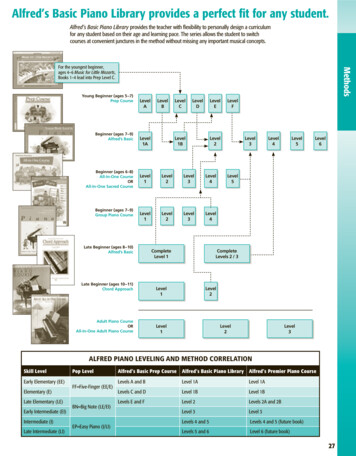
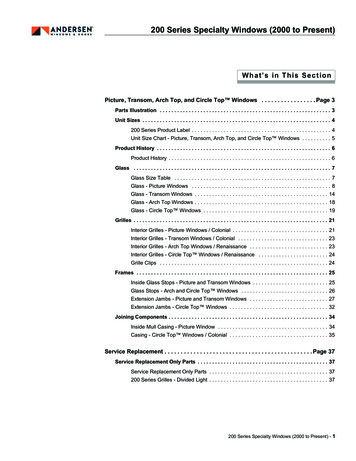
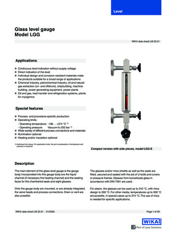
LevelGlass level gaugeModel LGGWIKA data sheet LM 33.01Applications Continuous level indication without supply voltage Direct indication of the level Individual design and corrosion-resistant materials makethe products suitable for a broad range of applications Chemical industry, petrochemical industry, oil and naturalgas extraction (on- and offshore), shipbuilding, machinebuilding, power generating equipment, power plants Oil and gas, heat transfer and refrigeration systems, plantsfor cryogenicsSpecial features Process- and procedure-specific production Operating limits:- Operating temperature: -196 . 374 C 1)- Operating pressure:Vacuum to 250 bar 1) Wide variety of different process connections and materials Illumination optional Heating and/or insulation optional1) Individual limit values. For application limits, the joint consideration of temperature andpressure is required!Compact version with side pieces, model LGG-EDescriptionThe main element of the glass level gauge is the gaugebody. Incorporated into this gauge body are the liquidchannel (if necessary the heating channel) and the seatingfaces for the chambered seals and sight glasses.The glasses and/or mica shields as well as the seals arefitted, secured and sealed with the aid of U-bolts and coversor pressure frames. Glasses from borosilicate glass inaccordance with DIN 7081 are used.Onto the gauge body are mounted, or are already integrated,the valve heads and process connections. Drain or vent arealso possible.For steam, the glasses can be used up to 243 C, with micadesign to 300 C. For other media, temperatures up to 300 Care possible, in special cases up to 374 C. The use of micais needed for specific applications.WIKA data sheet LM 33.01 01/2020Page 1 of 29
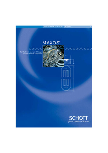
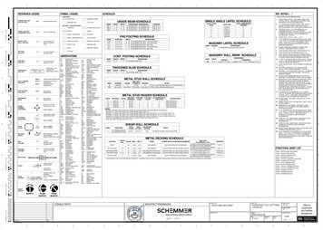
Operating principleReflex glasses per DIN 7081In the viewing direction, incident light strikes the reflectivegrooves of the sight glass plate and is refracted into the liquidpresent. With gases, the light is reflected. Thus the levelis visible as a dark column, the gaseous area as a silverycolumn over it.Reflex glasses are very well suited for the display of clearliquids.Viewing directionGaseous phaseViewing directionLiquid phaseTransparent glasses per DIN 7081From the rear, incident light passes through both sight glassplates with the media between them. The level is visible as aline (meniscus) or directly due to the liquid itself.Viewing directionper DIN 7081Refraction principle with mica shieldsFrom the rear, incident light from a lamp passes through bothmica shields with the medium between them. The lamp andmedium are arranged at an angle. In the gaseous phase, thelight passes directly through, with liquid, the light is refractedsideways. Thus the level is visible as a black column, thegaseous area as a light column over it.Viewing directionRefraction type with mica shieldsIf unprotected sight glasses are used in boiler systems with aqueous media, high temperatures and high pH values can lead toincreased glass erosion. The effect of glass corrosion is increased with the introduction of chemical additives, such as in watertreatment. The geometric changes to the sight glass resulting from the erosion lead to risks in the operational safety.For temperatures from 243 C, WIKA recommends the use of transparent glasses with mica design. These preventchemical attack at high water temperatures on the otherwise unprotected glass.WIKA data sheet LM 33.01 01/2020Page 2 of 29
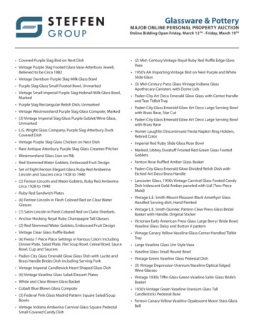
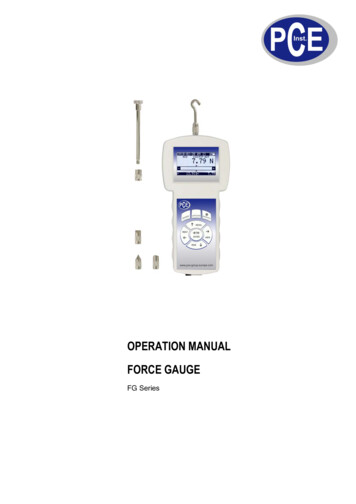
Construction of glass level gaugesGauge bodyBase body of the glass level gauge, contains the liquidchannelExampleCoverGauge bodyCoverFor the clamping of the sight glass platesFlat gasketChambered sealing between the liquid channel and theenvironmentGlassSight glass plates per DIN 7081 from borosilicate glassU-boltNutFlat gasketGlassCushionCushionMechanical protection between cover and glassU-bolt, nutHold the forces from the internal pressureGlass sizeStandard lengths L of sight glass plates per DIN 7081,width 34 mm, thickness 17 mmVisible length SLThe entire visible length in the sight glass, glass separationsare includedIndividual visible length ESLVisible range of a single segmentSegmentField of view consisting of a single sight glass plateGlass separation ANon-visible range, results from the linking together ofsegmentsWIKA data sheet LM 33.01 01/2020Page 3 of 29
Visible lengths and glass sizes in mmLengthGlass 380Number of segmentsVisible length 3702,5102,7202,930Matrix valid for glass separation A 45 mmThe visible length SL can deviate from the specified value by 3 mm due to construction.Valve headsValve heads isolate the vessel from the glass level gauge.They consist of the valve body and the head piece. They areactuated by a valve with quick closing lever or handwheel.In general, they are fitted with a ball-check valve as a safetyelement.Valve bodyHead pieceValve with quick closing leverValve with handwheelOpen anticlockwiseWIKA data sheet LM 33.01 01/2020Open anticlockwisePage 4 of 29
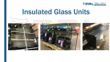
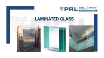
Ball-check valveThe ball-check valve should prevent any major spillagefrom the glass level gauge in the event of any glass ormica breakage or other sizable leakage. For this purposethere is, under the valve seat, a ball within a recess. Assoon as the indicator starts to leak, the incipient flow liftsthe ball from the recess and forces it against the valve seat(pressure 0.5 bar). In this way, the flow is sharply reduced.The closing of the valve presses the ball back into its startingposition.Illustration of the ball-check valve principleSituation in normal operationWIKA data sheet LM 33.01 01/2020Ball-check valve on glass breakSituation during commissioningPage 5 of 29
Model overviewGlass level gaugeMaterialDisplayMax. pressure Temperature Glassin barrange in CsizeNumber ofsegments“Carbon-Line” version,model LGG-RPSteel A350LF2Sight glass100-40 . 3004 . 91 . 5Compact version with sidepieces, model LGG-ESteel 1.0460/1.0570Sight glass40-10 . 3002 . 111 . 3Standard version,model LGG-RESteel 1.0570 (A350LF2)Sight glass160-10 . 3002 . 111 . 5High-pressure version,model LGG-RISteel 1.5415 (15Mo3)Sight glass250-10 . 1002 . 91 . 5Steel 1.0570 (A350LF2)Sight glass40-10 . 3002 . 91Steel A350LF2Glass(mica)100-40 . 3004 . 91 . 5Glass(mica)160-10 . 3002 . 111 . 5-10 . 1002 . 91 . 5-10 . 1002 . 91 . 5-10 . 3002 . 91-10 . 120-10 . 200110 .1,200 mm1-10 . 200150 .4,500 mm1 . 3-10 . 3742 . 111 . 9Reflex indicatorWeld-in version,model LGG-WRTransparent indicator“Carbon-Line” version,model LGG-TPStainless steel 1.4404 (316L)Stainless steel 1.4404 (316L)Stainless steel 1.4404 (316L)Standard version,model LGG-TESteel 1.0570 (A350LF2)High-pressure version,model LGG-TISteel 1.5415 (15Mo3)Glass(mica)250Steel 1.5415 (15Mo3)Glass mica160Steel 1.0570 (A350LF2)Glass(mica)40Superheated steamversion, model LGG-T3Weld-in version,model LGG-WTGlass tube, standard,model LGG-GAGlass tube, for large lengthswith interposing glassholder, model LGG-GBRefraction indicatorHighest-pressure version,model LGG-MStainless steel 1.4404 (316L)Stainless steel 1.4404 (316L)Stainless steel 1.4404 (316L)Stainless steel 1.4404 (316L)BrassGlass tubeStainless steel 1.4571 (316Ti) 13 mm10Stainless steel 1.4404 (316L)Glass tube16 mm25Steel 1.5415 (15Mo3)Mica160/250-196 . 300-196 . 100-196 . 300-196 . 300-196 . 100-196 . 300-196 . 300ExamplesModel LGG-RPModel LGG-EWIKA data sheet LM 33.01 01/2020Model LGG-TEModel LGG-RIPage 6 of 29
Model overview of valve headsValve headGlass tube fitting withhandwheel, model LGV-01MaterialValve bodyHead pieceStainless steelStainlesssteelGlass tube fitting with quickclosing lever, model LGV-03Stainless steelGlass tube fittingcompact with handwheel,model LGV-05 Brass Stainless steelStainlesssteelMax.Operationpressurein barBall-check MountvalveThruwayPN 250HandwheelYesTop, bottomOffsetPN 100Quick closing leverYesTop, bottomOffsetCompact glass tube fittingStainless steelwithout valve, model LGV-04StainlesssteelPN 10HandwheelNoTop, bottomAngledWithoutPN 10WithoutNoTop, bottomAngledDouble valve, model LGV-18 Steel 15Mo3StainlesssteelPN 160Double handwheel/ Yesdouble leverLateralAngledLateralAngledDouble valve, high pressure, Steel 15Mo3model LGV-19Forged valve withhandwheel, model LGV-33StainlesssteelSteel A350LF2,nitrocarburisedStainlesssteelPN 250Double handwheel/ Yesdouble leverPN 250HandwheelYesTop, bottomOffsetForged valve with quickclosing lever, model LGV-38Steel A350LF2,nitrocarburisedStainlesssteelPN 100Quick closing leverYesTop, bottomOffsetStraight valve withhandwheel, model LGV-51 Steel Sstainless steelStainlesssteelPN 250HandwheelYesLateral, backStraightPN 250HandwheelYesLateralAngledOffset valve withhandwheel, model LGV-53 Steel Sstainless steelStainlesssteelStainlesssteelPN 250HandwheelYesTop, bottomOffsetStainlesssteelPN 100Quick closing leverYesLateral, backStraightStainlesssteelPN 100Quick closing leverYesLateralAngledStainlesssteelPN 100Quick closing leverYesTop, bottomOffsetAngled valve withhandwheel, model LGV-52Straight valve with quickclosing lever, model LGV-56Angled valve with quickclosing lever, model LGV-57Offset valve with quickclosing lever, model LGV-58 Steel Sstainless steel Steel Sstainless steel Steel Sstainless steel Steel Sstainless steelExamplesModel LGV-33WIKA data sheet LM 33.01 01/2020Model LGV-57Model LGV-51Page 7 of 29
Valve head arrangementThe valve arrangement is always specified in relation to theviewing direction. Rotatable field of viewOffset valveTop and bottom mount Fixed field of viewStraight valveLeft mount (lateral)Straight valveBack mount, left-handGHLGLLAngled valveLeft mount (lateral)Angled valveBack mount, left-handELLWIKA data sheet LM 33.01 01/2020EHLStraight valveBack mount, right-handGHRAngled valveBack mount, right-handEHRStraight valveRight mount (lateral)GRRAngled valveRight mount (lateral)ERRPage 8 of 29
Glass level gauge, reflex, “Carbon-Line” versionModel LGG-RPValve arrangementSpecificationsMaterialSteel A350 LF2, nitrocarburisedCover80 x 30 mm, forgedMax. operating pressure100 bar 1)Gauge body40 x 40 mm, forgedSight glassBorosilicate, reflex per DIN 7081Temperature range-40 . 243 C (steam)-40 . 280 CProcess connections Centre-to-centre distance MFreely selectable, min. visible length SL 180 mmDrainPlug 1/2 NPT (option: Valve)Number of segments1 . 5Male thread 1/2 NPT, 3/4 NPTWeld stub 1/2", 3/4"Flange DIN/EN: DN 15 . 50, PN 16 . 100Flange ANSI: 1/2 . 2", class 150 . 600VentPlug 1/2 NPT (option: Valve)Glass size4 . 9Suitable valve headsHandwheelModel LGV-33 (PN 250)Quick closing leverModel LGV-38 (PN 100)1) Depending on the temperature, the material properties must be observedWIKA data sheet LM 33.01 01/2020Page 9 of 29
Glass level gauge, reflex, compact version with side piecesModel LGG-EAA-AASpecificationsMaterialSteel 1.0460, 1.0570CoverClamping through side components, hingedMax. operating pressure40 bar 1)Gauge body40 x 30 mm, machinedSight glassBorosilicate, reflex per DIN 7081Temperature range-10 . 243 C (steam)Process connections Flange DIN/EN: DN 15 . 50, PN 16 . 40 Flange ANSI: 1/2 . 2", class 150 . 300Centre-to-centre distance MFreely selectable, min. visible length SL 80 mmDrainPlug G 3/8 (option: Valve, ball valve)Number of segments1 . 3VentPlug G 3/8 (option: Valve, ball valve)Glass size2 . 11Suitable valve headsIntegrated, with ball-check valve, mounting components from stainless steel1) Depending on the temperature, the material properties must be observedValve arrangementHLWIKA data sheet LM 33.01 01/2020RPage 10 of 29
Glass level gauge, reflex, standard versionModel LGG-REVersion with valve head, lateral, model LGV-52SpecificationsVersion with valve head, top/bottom, model LGV-53Steel versionStainless steel versionMaterialSteel 1.0570, A350 LF2Stainless steel 1.4404 (316L)Cover 80 x 30 mm, forged (PN 40, size 4 . 9) 80 x 30 mm, machined (PN 40) 80 x 40 mm, machined (PN 100, PN 160) 80 x 30 mm, machined (PN 40) 80 x 40 mm, machined (PN 100, PN 160)40 x 40 mm, machinedGauge bodyBorosilicate, reflex per DIN 7081Sight glassMax. operating pressure 40 bar, 100 bar, 160 bar 1)Temperature rangeProcess connections-10 . 243 C (steam)-10 . 300 C -196 . 243 C (steam)-196 . 300 CMale thread 1/2 NPT, 3/4 NPTWeld stub 1/2", 3/4"Flange DIN/EN: DN 15 . 50, PN 16 . 160Flange ANSI: 1/2 . 2", class 150 . 900 Freely selectable, min. visible length SL 180 mm (with mounted valve heads model LGV-33, LGV-38, LGV-53, LGV-58) Freely selectable, min. visible length SL 80 mm (with mounted valve heads model LGV-51, LGV-52, LGV-56, LGV-57) Special version, visible length M (with mounted valve heads model LGV-51, LGV-52, LGV-56, LGV-57)Centre-to-centredistance MPlug G 3/8 (option: Weld stub, flange, valve or ball valve)VentPlug G 3/8 (option: Weld stub, flange, valve or ball valve)DrainGlass sizeNumber of segmentsSuitable valve headsHandwheelQuick closing lever2 . 111 . 5 (more on request)Model LGV-33, LGV-51, LGV-52, LGV-53 (PN 250)Model LGV-38, LGV-56, LGV-57, LGV-58 (PN 100)Other materials on requestModel LGV-51, LGV-56GHLModel LGV-56, LGV-57, LGV-58 (PN 100)1) Depending on the temperature, the material properties must be observedValve arrangementGLLModel LGV-51, LGV-52, LGV-53 (PN 250)Model LGV-52, LGV-57GHRWIKA data sheet LM 33.01 01/2020GRRELLEHLModel LGV-33, LGV-38,LGV-53, LGV-58EHRERRPage 11 of 29
Glass level gauge, reflex, high-pressure versionModel LGG-RIVersion with valve head, lateral, model LGV-52Version with valve head, top/bottom, model LGV-53Viewing directionSpecificationsSteel versionStainless steel versionGauge body140 x 40 mm, machinedSight glassBorosilicate, reflex per DIN 7081Steel 1.5415 (15Mo3)MaterialCoverPressure frameMax. operating pressure250 bar 1)Stainless steel 1.4404 (316L)-10 . 100 CTemperature range-196 . 100 CMale thread 1/2 NPT, 3/4 NPTWeld stub 1/2", 3/4"Flange DIN/EN: DN 15 . 50, PN 16 . 250Flange ANSI: 1/2 . 2", class 150 . 1,500Process connections Centre-to-centre distance M Freely selectable, min. visible length SL 180 mm (with mounted valve head model LGV-53) Freely selectable, visible length SL M (with mounted valve heads model LGV-51, LGV-52)VentPlug G 3/8 (option: Weld stub, flange, valve or ball valve)Glass size2 . 9DrainPlug G 3/8 (option: Weld stub, flange, valve or ball valve)Number of segments1 . 5Suitable valve headsHandwheelModel LGV-51, LGV-52, LGV-53Other materials on request1) Depending on the temperature, the material properties must be observedValve arrangementGLLGHLModel LGV-53Model LGV-52Model LGV-51GHRWIKA data sheet LM 33.01 01/2020GRRELLEHLEHRERRPage 12 of 29
Glass level gauge, reflex, weld-in versionModel LGG-WRFront viewSpecificationsRear viewslottedSteel versiondrilledStainless steel versionMaterialSteel 1.0570Cover40 x 40 mm, machinedMax. operating pressure40 bar 1) (display must be included in the pressure test for the vessel)Gauge body40 x 40 mm, machinedSight glassBorosilicate, reflex per DIN 7081Temperature range-10 . 243 C (steam)-10 . 300 COverall length GLVisible length SL 43 mmNumber of segments1Glass sizewith weld stubStainless steel 1.4404 (316L)-196 . 243 C (steam)-196 . 300 C2 . 9 (larger on request)Other materials on request1) Depending on the temperature, the material properties must be observedWIKA data sheet LM 33.01 01/2020Page 13 of 29
Glass level gauge, transparent, “Carbon-Line” versionModel LGG-TPSpecificationsMaterialSteel A350 LF2, nitrocarburisedCover80 x 34 mm, forgedGauge bodySight glassMax. operating pressureTemperature rangeProcess connections40 x 40 mm, forgedBorosilicate, transparent per DIN 7081 (option: Mica design)100 bar 1)-40 . 243 C (steam, without mica design)-40 . 300 C (steam, with mica design)-40 . 300 C Male thread 1/2 NPT, 3/4 NPTWeld stub 1/2", 3/4"Flange DIN/EN DN 15 . 50, PN 16 . 100Flange ANSI 1/2 . 2", class 150 . 600Centre-to-centre distance MFreely selectable, min. visible length SL 180 mmDrainPlug 1/2 NPT (option: Valve)VentGlass sizeNumber of segmentsSuitable valve headsHandwheelQuick closing leverPlug 1/2 NPT (option: Valve)4 . 91 . 5Model LGV-33 (PN 250)Model LGV-38 (PN 100)Other materials on request1) Depending on the temperature, the material properties must be observedValve arrangementWIKA data sheet LM 33.01 01/2020Page 14 of 29
Glass level gauge, transparent, standard versionModel LGG-TEVersion with valve head, lateral, model LGV-52SpecificationsSteel versionGauge body40 x 40 mm, machinedVersion with valve head, top/bottom, model LGV-53Stainless steel versionSteel 1.0570, A350 LF2MaterialStainless steel 1.4404 (316L)80 x 30 mm, forged (PN 40, size 4 . 9)80 x 30 mm, machined (PN 40)80 x 40 mm, machined (PN 100, PN 160)Cover80 x 30 mm, machined (PN 40)80 x 40 mm, machined (PN 100, PN 160)Borosilicate, transparent per DIN 7081 (option: Mica design)Sight glassMax. operating pressure 40 bar, 100 bar, 160 bar 1)Temperature rangeProcess connections-10 . 243 C (steam, without mica design)-10 . 300 C (steam, with mica design)-10 . 300 C-196 . 243 C (steam, without mica design)-196 . 300 C (steam, with mica design)-196 . 300 CMale thread 1/2 NPT, 3/4 NPTWeld stub 1/2", 3/4"Flange DIN/EN DN 15 . 50, PN 16 . 160Flange ANSI 1/2 . 2", class 150 . 900 Freely selectable, min. visible length SL 180 mm (with mounted valve heads model LGV-33, LGV-38, LGV-53, LGV-58) Freely selectable, min. visible length SL 80 mm (with mounted valve heads model LGV-51, LGV-52, LGV-56, LGV-57) Special version, visible length M (with mounted valve heads model LGV-51, LGV-52, LGV-56, LGV-57)Centre-to-centredistance MPlug G 3/8 (option: Weld stub, flange, valve or ball valve)VentPlug G 3/8 (option: Weld stub, flange, valve or ball valve)DrainGlass sizeNumber of segmentsSuitable valve headsHandwheelQuick closing lever2 . 111 . 5 (more on request)Model LGV-33, LGV-51, LGV-52, LGV-53 (PN 250)Model LGV-38, LGV-56, LGV-57, LGV-58 (PN 100)Other materials on requestModel LGV-33, LGV-38,LGV-53, LGV-58Model LGV-52, LGV-57Model LGV-51, LGV-56GHLModel LGV-56, LGV-57, LGV-58 (PN 100)1) Depending on the temperature, the material properties must be observedValve arrangementGLLModel LGV-51, LGV-52, LGV-53 (PN 250)GHRWIKA data sheet LM 33.01 01/2020GRRELLEHLEHRERRPage 15 of 29
Glass level gauge, transparent, high-pressure versionModel LGG-TIVersion with valve head, lateral, model LGV-52Version with valve head, top/bottom, model LGV-53Viewing directionSpecificationsSteel versionStainless steel versionSteel 1.5415 (15Mo3)MaterialStainless steel 1.4404 (316L)Gauge body140 x 40 mm, machinedSight glassBorosilicate, transparent per DIN 7081Pressure frameCover250 bar 1)Max. operating pressure-10 . 100 CTemperature rangeMale thread 1/2 NPT, 3/4 NPTWeld stub 1/2", 3/4"Flange DIN/EN DN 15 . 50, PN 16 . 250Flange ANSI 1/2 . 2", class 150 . 1,500-196 . 100 CProcess connections Centre-to-centre distance M Freely selectable, min. visible length SL 180 mm (with mounted valve head model LGV-53) Freely selectable, visible length SL M (with mounted valve heads model LGV-51, LGV-52)Plug G 3/8 (option: Weld stub, flange, valve or ball valve)VentPlug G 3/8 (option: Weld stub, flange, valve or ball valve)Drain2 . 9Glass size1 . 5Number of segmentsSuitable valve headsHandwheelModel LGV-51, LGV-52, LGV-53Other materials on request1) Depending on the temperature, the material properties must be observedValve arrangementGLLGHLModel LGV-53Model LGV-52Model LGV-51GHRWIKA data sheet LM 33.01 01/2020GRRELLEHLEHRERRPage 16 of 29
Glass level gauge, transparent, superheated steam versionModel LGG-T3Version with valve head, lateral, model LGV-52Version with valve head, top/bottom, model LGV-53Viewing directionSpecificationsSteel versionStainless steel versionSteel 1.5415 (15Mo3)MaterialStainless steel 1.4404 (316L)Gauge body140 x 40 mm, machinedSight glassBorosilicate, transparent per DIN 7081 (with mica design)Temperature range-10 . 300 CCoverPressure frameMax. operating pressure160 bar 1)Process connections Centre-to-centredistance M Freely selectable, min. visible length SL 180 mm (with mounted valve head model LGV-53) Freely selectable, visible length SL M (with mounted valve heads model LGV-51, LGV-52)-196 . 300 CMale thread G 1/2, G 3/4, 1/2 NPT, 3/4 NPTWeld stub 1/2", 3/4"Flange DIN/EN DN 15 . 50, PN 16 . 100Flange ANSI 1/2 . 2", class 150 . 600VentPlug G 3/8 (option: Weld stub, flange, valve or ball valve)Glass size2 . 9DrainPlug G 3/8 (option: Weld stub, flange, valve or ball valve)Number of segments1 . 5Suitable valve headsHandwheelModel LGV-51, LGV-52, LGV-53Other materials on request1) Depending on the temperature, the material properties must be observedValve arrangementModel LGV-51GLLGHLModel LGV-52GHRWIKA data sheet LM 33.01 01/2020GRRELLModel LGV-53EHLEHRERRPage 17 of 29
Glass level gauge, transparent, weld-in versionModel LGG-WTFront viewRear viewslotteddrilledwith weld stubSpecificationsSteel versionGauge body80 x 40 mm, machinedCover 80 x 30 mm, forged (size 4 . 9) 80 x 30 mm, machinedSight glassBorosilicate, transparent per DIN 7081 (option: Mica design)Temperature range-10 . 243 C (steam, without mica design)-10 . 300 C (steam, with mica design)-10 . 300 COverall length GLVisible length SL 43 mmNumber of segments1MaterialMax. operating pressureGlass sizeSteel 1.0570Stainless steel versionStainless steel 1.4404 (316L)80 x 30 mm, machined40 bar 1) (display must be included in the pressure test for the vessel)-196 . 243 C (steam, without mica design)-196 . 300 C (steam, with mica design)-196 . 300 C2 . 9 (larger on request)1) Depending on the temperature, the material properties must be observedOther materials on requestWIKA data sheet LM 33.01 01/2020Page 18 of 29
Glass level gauge, glass tube, standardModel LGG-GAVersion without valve(only stainless steel)SpecificationsVersion with valve(brass or stainless steel)Version without valveMaterialStainless steel 1.4571Max. operating pressure10 bar 1)Version with valveStainless steel 1.4571 or brass 2.0401Sight glassGlass tube, borosilicate, diameter 13 mmTemperature range-10 . 80 C (with plexi protective cover)-10 . 150 C (with stainless steel protection)Process connectionsMale thread G 1/2Flange DIN/EN DN 15 . 25, PN 10Centre-to-centre distance M110 . 1,200 mm, visible length SL 70 mm150 . 1,200 mm, visible length SL 110 mmVentPlug G 3/8Plug G 1/2DrainPlug G 3/8Plug G 1/2Glass sizeCentre-to-centre distance M - 20 mmCentre-to-centre distance M - 65 mmNumber of segments1Suitable valve headsGlass tube fittingModel LGV-04-10 . 200 CModel LGV-051) Depending on the temperature, the material properties must be observedOther materials on requestWIKA data sheet LM 33.01 01/2020Page 19 of 29
Glass level gauge, glass tube, for large lengths with interposing glass-holderModel LGG-GBSpecificationsMaterialStainless steel 1.4404 (316L)Max. operating pressure25 bar 1)Process connections Male thread G 1/2 Flange DIN/EN DN 15 . 25, PN 25Centre-to-centre distance M150 . 4,500 mm, visible length SL 130 mmDrainPlugNumber of segments1 . 3Sight glassGlass tube, borosilicate, diameter 16 mmTemperature range-10 . 200 CVentPlugGlass size150 . 4,500 mm (use interposing glass-holder from 1,500 mm)Suitable valve headsHandwheelQuick closing leverModel LGV-01Model LGV-031) Depending on the temperature, the material properties must be observedOther materials on requestWIKA data sheet LM 33.01 01/2020Page 20 of 29
Glass level gauge, refraction, highest-pressure versionModel LGG-MValve arrangementModel LGV-18, LGV-19ELLSpecificationsMaterialSteel 1.5415 (15Mo3)CoverPressure frameMax. operating pressure250 bar 1)Gauge body140 x 40 mm, machinedSight glassMica package (sight glass separation 120 mm)Temperature range-10 . 374 CProcess connections Flange DIN/EN DN 15 . 50, PN 16 . 250 Flange ANSI 1/2 . 2", class 150 . 2,500Centre-to-centre distance MFreely selectable, min. visible length SL 80 mmDrainPlug G 3/8 (option: Weld stub, flange, valve or ball valve)Number of segments1 . 9VentPlug G 3/8 (option: Weld stub, flange, valve or ball valve)Glass size2 . 11Suitable valve headsHandwheel and quick closingleverERR Model LGV-19 (PN 250) Model LGV-18 (PN 160)1) Depending on the temperature, the material properties must be observedOther materials on requestWIKA data sheet LM 33.01 01/2020Page 21 of 29
Valve headsModel LGV-01Glass tube fitting with handwheelModel LGV-03Glass tube fitting with quick closing leverModel LGV-04Compact glass tube fitting without valveWIKA data sheet LM 33.01 01/2020SpecificationsMaterialsValve bodyStainless steelHead pieceStainless ion to gauge bodyGlass tube 16Thru-wayOffsetValve stem threadInternalBall-check valveYesPressure rangePN 25MountTop/bottomRotatableYesSeat positionInlineDrainYesSpecificationsMaterialsValve bodyStainless steelHead pieceStainless steelConstructionMachinedOperationQuick closing leverConnection to gauge bodyGlass tube 16Thru-wayOffsetValve stem threadInternalBall-check valveYesPressure rangePN 25MountTop/bottomRotatableYesSeat positionInlineDrainNoSpecificationsValve body materialStainless steel 1.4571Pressure rangePN 25MountTop/bottomRotatableYesSeat positionWithoutDrainYes, G 3/8ConstructionCastOperationWithoutConnection to gauge bodyGlass tube 13.5Thru-wayAngledValve stem threadWithoutBall-check valveNoPage 22 of 29
Model LGV-05Compact glass tube fitting with handwheelModel LGV-18Double valveModel LGV-19Double valve, high pressureWIKA data sheet LM 33.01 01/2020SpecificationsMaterialsValve body Brass 2.0401 Stainless steel 1.4571Head pieceStainless ion to gauge bodyGlass tube 13.5Thru-wayAngledValve stem threadInternalBall-check valveNoPressure rangePN 10MountTop/bottomRotatableYesSeat positionInlineDrainYes, G 1/4SpecificationsMaterialsValve bodySteel 15Mo3Head pieceStainless steelConstructionForgedOperationDouble handwheel / leverConnection to gauge bodyFlangedThru-wayAngledValve stem threadInternalBall-check valveYesPressure rangePN 160MountLateralRotatableNoSeat positionInlineDrainNoSpecificationsMaterialsValve bodySteel 15Mo3Head pieceStainless steelConstructionMachinedOperationDouble handwheel / leverConnection to gauge bodyFlangedThru-wayAngledValve stem threadInternalBall-check valveYesPressure rangePN 250MountLateralRotatableNoSeat positionInlineDrainNoPage 23 of 29
Model LGV-33Forged valve with handwheelModel LGV-38Forged valve with quick closing leverModel LGV-51, straight valve with handwheelSpecificationsMaterialsValve bodySteel A350 LF2Head pieceStainless n to gauge bodyScrewed nippleThru-wayOffsetValve stem threadInternalBall-check valveYesPressure rangePN 250MountTop/bottomRotatableYesSeat positionInlineDrainYes, 1/2 NPTSpecificationsMaterialsValve bodySteel A350 LF2Head pieceStainless steelConstructionForgedOperationQuick closing leverConnection to gauge bodyScrewed nippleThru-wayOffsetValve stem threadInternalBall-check valveYesPressure rangePN 250MountTop/bottomRotatableYesSeat positionInlineDrainYes, 1/2 NPTSpecificationsMaterialsWIKA data sheet LM 33.01 01/2020Valve bodySteel, stainless steelHead pieceStainless ion to gauge bodyScrewed nippleThru-wayStraightValve stem threadInternalBall-check valveYesPressure rangePN 250MountLateral/backRotatableNoSeat positionInlineDrainNoPage 24 of 29
Model LGV-52Angled valve with handwheelModel LGV-53Offset valve with handwheelModel LGV-56straight valve with quick closing leverWIKA data sheet LM 33.01 01/2020SpecificationsMaterialsValve bodySteel, stainless steelHead pieceStainless ion to gauge bodyScrewed nippleThru-wayAngledValve stem threadInternalBall-check valveYesPressure rangePN 250MountLateralRotatableNoSeat positionInlineDrainNoSpecificationsMaterialsValve bodySteel, stainless steelHead pieceStainless ion to gauge bodyScrewed nippleThru-wayOffsetValve stem threadInternalBall-check valveYesPressure rangePN 250MountTop/bottomRotatableYesSeat positionInlineDrainYesSpecificationsMaterialsValve bodySteel, stainless steelHead pieceStainless steelConstructionMachinedOperationQuick closing leverConnection to gauge bodyScrewed nippleThru-wayStraightValve stem threadInternalBall-check valveYesPressure rangePN 100MountLateral/backRotatableNoSeat positionInlineDrainNoPage 25 of 29
Model LGV-57Angled valve with quick closing leverModel LGV-58Offset valve with quick closing leverWIKA data sheet LM 33.01 01/2020SpecificationsMaterialsValve bodySteel, stainless steelHead pieceStainless steelConstructionMachinedOperationQuick closing leverConnection to gauge bodyScrewed nippleThru-wayAngledValve stem threadInternalBall-check valveYesPressure rangePN 100MountLateralRotatableNoSeat positionInlineDrainNoSpecificationsMaterialsValve bodySteel, stainless steelHead pieceStainless steelConstructionMachinedOperationQuick closing leverConnection to gauge bodyScrewed nippleThru-wayOffsetValve stem threadInternalBall-check valveYesPressure rangePN 100MountTop
The glasses and/or mica shields as well as the seals are fitted, secured and sealed with the aid of U-bolts and covers or pressure frames. Glasses from borosilicate glass in accordance with DIN 7081 are used. For steam, the glasses can be used up to 243 C, with mica design to 300 C. For other media, temperatures up to 300 C