Transcription
IGVC-2019-IGOROld Dominion UniversityBatten College of Engineering & TechnologyIntelligent Ground Operating Robot “IGOR”Date Submitted: May 15, 2019Team Captains:Bonnie Lee Miley (bmil001@odu.edu)Dana Pelland (dpell001@odu.edu)Team Members:Mark Boyd (mboyd002@odu.edu)Craig Earls (cearl001@odu.edu)Jackie Edmiston (jedmi001@odu.edu)Jason Felton (jfelt013@odu.edu)Susana Long (slong001@odu.edu)Carlos Martinez (cmart022@odu.edu)David Osafo (dosaf001@odu.edu)Preslav Ivanov (pivan001@odu.edu)Ryan Miller (rmill001@odu.edu)Taylor Roy (troyx001@odu.edu)Justin Rush (jrush004@odu.edu)Chase Vogler (cvosl001@odu.edu)Graduate Adviser: Adam Seay (aseay001@odu.edu)Intern: Ryan Redmon (rredm002@odu.edu)We, the students of Old Dominion University, aspire to be honest and forthright in our academic endeavors.Therefore, we will practice honesty and integrity and be guided by the tenets of the Monarch Creed. We will meetthe challenges to be beyond reproach in our actions and our words. We will conduct ourselves in a manner thatcommands the dignity and respect that we also give to others.In addition, and as the faculty advisor, I hereby certify that the design and engineering of the vehicle (original orchanges) by the current student team has been significant and equivalent to what might be awarded credit in asenior design course.Faculty Adviser: Dr. Lee A. Belfore (lbelfore@odu.edu)
2Conduct of design process, team identification and team organizationIntroductionThis paper represents the conceptual design of our vehicle, IGOR, and its components. Theautonomous vehicle, IGOR, must navigate a course through lane detection and waypoint capabilities.While much of the functionality was stated to exist, verification and validation was necessary as was thesafety and integration of the software. The quantitative measure of success will be the implementation ofall of the qualifying requirements of the Auto-Nav competition.Given the current implementation, the design methodology implemented is Continuous ProcessImprovement, specifically the DMAIC (Design, Measure, Analyze, Improve, and Control) principle. TheDMAIC principle is considered a Lean Six Sigma (LSS) method looked upon favorably by governmentagencies because it focuses on the reduction of waste and simplification of processes. The letters withinthe principle itself are the abbreviations for the five phases of the Six Sigma Improvement [1]. By usingthis process, we started out by defining the existing project, developing a plan built around improving thatproject, defining the improvement process within the plan, and evaluating the existing project’s progress[1]. From there, we needed to measure and collect all current data and analyze it [1]. Lastly, we need tomove to improve the different items and systems on the project and organize ways to continuouslymeasure and evaluate the progress accomplished within the project [1]. This methodology has allowed usto stay focused on the core design requirements of the competition. Once met, optimization of thevehicle’s functionality related to the core design requirements will be addressed.OrganizationThis project is the culmination of predecessor teams, operating independently and often withcomplete redesigns. This year we have moved towards vertical integration by incorporating thepreparatory design team into the current design team and creating a unique collaborative effort thatutilizes a Lean Six Sigma (LSS) process of gap analysis and Continuous Process Improvement (CPI) toensure the teams’ success. The competition team is interdisciplinary in nature and comprised of twodistinct Electrical and Computer Engineering Senior Design II undergraduate engineering students andhas primarily prepared not only to compete in the IGVC Design component, but also qualify for the AutoNav challenge.Given the University's upward trend in the Auto-Nav challenge, Ms. Miley’s teams’ primary taskis to ensure qualification for the 2019 IGVC. Ms. Pelland’s team is focused on qualifying for the IOP andCyber challenges, which is new for Old Dominion University this year.The competition team has been split into four sub-teams, which are focused on documentation,safety, hardware, and software. Several team members share duties spanning several sub-teams, whilesome members have taken on more singular roles.NameBonnie Lee MileyDana Pelland1Computer EngineeringMajorPrimarySecondaryCpE1Team CaptainScheduling/Quality Control/LabTours/Fundraising
3ECE2Susana LongTaylor RoyCpEECEProject LeadDocumentation/AssignmentsCraig EarlsRyan MillerEE3EEHardware LeadSafety SupportJackie EdmistonJustin RushEEECEHardware SupportEngineering StandardsFinanceCarlos MartinezCpEHardware SupportRequirementsJason FeltonChase VoslerECECpESoftware LeadFinanceMark BoydPreslav IvanovCpEECESoftware SupportLab Tour SupportDavid OsafoCpESafety LeadRealistic ConstraintsTable 1 – Tasks and ResponsibilitiesDesign assumptions and design processOur assumption in the design was to have an autonomous vehicle that would not only qualify but competein the Auto-Nav competition. In conjunction, our design process involved integrating hardware andsoftware together to tackle line detection and image processing. Furthermore, a replacement of theLiDAR and enclosure to prevent damage to the component was part of the design process. Safety lightswere to be fixated on the vehicle as well as safety modifications.The design expectations and process are in accordance with the 2019 IGVC Rules4. Our mainfocus is fulfilling the four requirements, detailed in this section, which were not met during the 2018competition as well as ensuring there are no changes to those specifications met via regression testing.Safety LightsThe vehicle is currently equipped with Light Emitting Diodes (LEDs) on the exterior of thevehicle chassis. These will be used to indicate the current state of the vehicle, which will be eitherStandby mode, Autonomous mode, or Error mode. The colors used to indicate these different modes areexpected to be green, blue, and red.Lane Detection and FollowingThe vehicle is expected to determine a lane in front of it. Once a lane is distinguished, the vehicleis to maneuver within that lane.2Electrical Engineering and Computer Engineering (Dual Major)Electrical Engineering4http://www.igvc.org/2019rules.pdf3
4Obstacle Detection and AvoidanceThe vehicle currently detects objects with the use of the A3 LiDAR. After further softwaredevelopment, the vehicle is expected to move around obstacles that are detected by the A3 LiDAR whilein a lane.Waypoint NavigationThe vehicle must be able to detect different GPS waypoints with the help of the newly acquiredcellular LTE. Once the waypoints are detected, the vehicle is expected to navigate to the waypoint andavoid any obstacles along the way.Effective innovations considered in your vehicle designThere are several aspects of IGOR that could be improved upon related to both hardware andsoftware. These improvements do not have direct bearing on the ability to qualify at the competition, butthey do include both hardware and software implementations/improvements.Implementing additional object detection hardware: The Microsoft Kinect is an existing hardwarealready designed for 3D object detection and tracking. We could use this in addition to our LiDAR toassist with the detection and distancing functionality. In addition, this would be a safety enhancement.The LiDAR is top-mounted and we cannot detect distance of objects that are below it, creating a potentialsafety hazard for the vehicle, small children, plants and animals.Utilizing license-free software alternatives: Since MATLAB5 is a licensed product, an attempt to translateour implementation into a marketable product would be require substantial capital. An open-sourcealternative to MATLAB would remove that hurdle to a profitable venture.Innovative technology applied to your vehicleReplacing batteries: The car batteries currently being used are heavy, pose a fire hazard when charging,and current flow decreases as they discharge. These batteries can be immediately replaced with anyalternative 12-volt battery and immediately provide better performance for the weight and, given thecharacteristics of lead-acid batteries, spend much less time charging.Reducing footprint of electrical/electronic components: IGOR has a Standard-ATX motherboard installedwhich could be replaced by using a smaller motherboard, Next Unit of Computing (NUC), or a RaspberryPi 3 Model B to reduce size of the electrical components. While it is possible for us to reduce the size ofthe electrical hardware, we cannot reduce the overall size of our vehicle due to design specifications ofthe competition. If we choose to reduce this footprint it could prove beneficial for uses outside thecompetition and future implementations.Replacing drive motors: A smaller and more economical motor would allow IGOR to run for longerperiods of time, thus increasing efficiency. IGOR currently operates with a 24-volt motor, and if we chose5MATLAB is a multi-paradigm numerical computing environment and proprietary programming languagedeveloped by MathWorks
5to replace drive motors, we could easily reduce the number of batteries. We are in the process ofprocuring additional information related to the current motor and once available, we will determine thebest way to move forward to ensure efficiency related to current draw. Innovative concept(s) from othervehicles were not designed into our vehicle.Description of mechanical designOverviewThe current implementation is the same motorized wheelchair-based vehicle that participated inthe 2018 IGVC in which predecessors successfully met four of the seven criteria for qualification.Navigation was done by creating a costmap which is populated using hits from the Light Detection andRanging (LiDAR) sensor. A Mini-Dome security camera was used for edge and pothole detection.Maneuverability algorithms were used to process the edge detection, to ensure that the vehicle does notgo out of bounds.Decision on frame structure, housing, structure designSuspension and weatherproofingThe current design is comprised of a wheelchair base, with a waterproof/weatherproof case, 2Arduino(s), 2 Raspberry Pi(s), DC/DC boost and buck converter(s), Sabretooth Motor Controller, and aU-blox ZED-F9P GPS module. The existing case was designed by a predecessor team and is a waterproofcase.Software Development and StrategyPrevious teams began development on a Convolutional Neural Network (CNN) for objectdetection which we have deemed non-essential for competition due to time constraints, this will berevisited post-competition as an optimization to our obstacle detection/avoidance algorithm.Implementation of edge detection was in place at the time we inherited the design. A largesoftware development effort was necessary related to the core design requirements.Outside of safety issues, the highest priority this team had was related to software development.With the predecessor team, the Regional Convolutional Neural Network (R-CNN) had been successfullytrained to identify orange pylons kept within our lab. The R-CNN was to be utilized in many differentaspects within the software. However, after analyzing resources and calculating the amount of man hoursneeded to implement it, the R-CNN was deemed too strenuous to continue as the main design for thesoftware development team.Instead, the software development team is developing four separate programs that are required toexecute independently for qualification and must be integrated for competition. These programsencompass the functionality that satisfies the core design requirements: lane detection/following, obstacledetection/avoidance, waypoint navigation and status indicators (using the LED strip) from a softwareperspective.
6Integration of these programs is necessary as the competition encompasses numerous challengeswhich will test all functionalities at varying different times while traversing the course. To ensureseamless integration, the software is being created with specific ROS variables, thus allowing eachprogram the ability to communicate with each other.ROS has different libraries that directly support development in C and OpenCV programminglanguages. The software development team has already designed and implemented programs related tothe core design requirement, lane detection/following and status indicators. Several tests have beenconducted and testing remains ongoing in an effort to determine the efficiency. The software developmentteam is actively working on the two remaining core design requirements obstacle detection/avoidance andwaypoint navigation to ensure proper testing and software integration to prove vehicle control duringperformance events.The existing design incorporates Robot Operating System (ROS), C , Python and OpenCV.Description of electronic and power designOverviewThe vehicle uses the base of a motorized wheelchair for locomotive purposes and has a weatherresistant case for housing the computers and electronics mounted on top of the base. The primary sensoris an A3 LiDAR (upgraded model) which uses light from a laser as a radar system which is used for ourprimary obstacle detection which creates a 2D environment map in the ROS software. Secondary sensorsinclude the Mini-Dome Network Camera which will also be used as a secondary obstruction detectionsensor and a thermal imaging camera. An LED strip surrounding the vehicle will alert users and observersalike to the status of the vehicle, and an electrically actuated mechanical relay will cut power to themotors when triggered by the wireless or wired emergency stop (E-stop) buttons.Power distribution system (capacity, max. run time, recharge rate, additional innovativeconcepts)A new hardware bundle has been designed and built. The new bundle uses two (2) Raspberry PiB instead of a PC motherboard for data processing. This amounts to a 120 square inch footprintreduction. This smaller footprint will allow for additional multiple processors as required in the future.The new bundle also includes a new GPS device which uses correction data over a cellular internetconnection to increase our location precision from over 1.5 meters to 10 millimeters. This is in directresponse to our problem of not qualifying in last year's competition due partially on a failed GPSwaypoint navigation test. A new 60 amp per channel motor controller replaces a 20 amp per channel onewhich will allow our wheel motors to run at full speed.To allow for the gathering of GPS correction data we have added a cellular Long Term Evolution(LTE) hat to one of our microprocessors. A Power over Ethernet (POE) switch has been added tominimize the amount of wires traversing our case. The POE switch allows us to remove the power cablesto our cameras and the Raspberry Pi. Using the POE switch and Pi allows us to remove a 58 square inchpower supply and replace it with two (2) 10 square inch DC/DC converters. These changes clearly reflecta design that is an efficient use of power, material and space.Electronics suite description including CPU and sensors system integration/feedback conceptsA proper wiring diagram was designed prior to working on this project and implementingchanges.
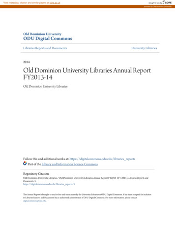
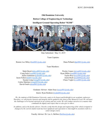
7Figure 1 – Wiring DiagramFigure 2 - Before and After Component LayoutSafety devices and their integration into your systemOne of the first issues addressed was the damaged LiDAR. The equipment itself has beenupgraded and the primary concern was to ensure the new LiDAR was adequately protected goingforward. A new mount satisfied our equipment safety concern. This mount and a screw on cover wasdesigned and 3D printed by our Hardware Lead. The cover will provide additional protection while not inuse. Integration testing of the LiDAR with the vehicle is in process.
8Figure 3 - New LiDAR Mount and CoverPrevious use of an active camera was deemed inefficient and exploration into the costeffectiveness of passive night vision solutions (not requiring IR or other illumination sources) was done.Additional funding, outside of our major sponsor, was obtained through the College Projects Committeeand we have procured an adequate passive camera. Image intensification was discussed, but given thepriority of the core design requirements, was passed to our successor team for implementation.The Pixy cameras previously used for lane following and pothole detection were also damaged,deemed inefficient, and removed, the 4MP IR Mini-Dome Network Camera used in conjunction with thePixy cameras will be the primary means for lane detection/following in order to meet the core designrequirements in a timely fashion.Description of software strategy and mapping techniques Systems IntegrationOverviewROS is the software previously used for device management, sensor data, transfer of messagesbetween publishers and subscribers, and in conjunction with the Mini-Dome Network Camera allowed forthe publishing of images using OpenCV. The vehicle utilizes ROS, C , and OpenCV within a programwhich allows the vehicle to detect a lane in front of it. Once detected, the vehicle travels through the lane.This is done by transmitting values to the motor controller and the not only propel the vehicle forwardwithin the lane, but also help maintain the vehicle’s position around the center of the lane. In addition, anA3 LiDAR has been integrated with ROS to detect objects around the vehicle.Obstacle detection and avoidanceThe vehicle is expected to determine a lane in front of it. Once a lane is distinguished, the vehicleis to maneuver within that lane. The vehicle currently detects objects with the use of the A3 LiDAR. Afterfurther software development, the vehicle is expected to move around obstacles that are detected by theA3 LiDAR while in a lane.Software strategy and path planning, map generation and goal selection and path generationA GPS is required for waypoint navigation. However, with an accuracy of 1.5 meters, theprevious GPS lacked the accuracy to complete the competition and the waypoints were not beingtranslated properly. The GPS needed to either be replaced or an advanced algorithm developed that could
9process additional data to meet the core design requirement. Given the software development teamneeded to redefine the lane detection/following algorithm, a new GPS was procured.The vehicle must be able to detect different GPS waypoints with the help of the newly acquiredcellular LTE. Once the waypoints are detected, the vehicle is expected to navigate to the waypoint andavoid any obstacles along the way. Additional creative concepts have been placed on hold due to theimportance of qualifying for competition.Description of failure modes, failure points and resolutionsVehicle failure modes (software, mapping, etc.) and resolutionsSafety LightsThe vehicle is currently equipped with Light Emitting Diodes (LEDs) on the exterior of thevehicle chassis. Requirements dictate a status indicator on the vehicle. These LEDs operate in thatcapacity and we have utilized the following colors and corresponding modes: green indicates Standbymode, blue indicates Autonomous mode, and red indicates Error mode. Standby mode correlates to IGORoperating as expected and/or awaiting input from internal command or the user. Autonomous mode willbe situated around all times where IGOR is moving free of user control. This will encompass times whereIGOR is solely using software to accomplish different tasks within the competition. Any time an error isencountered, either while completing a task, in Standby or Autonomous mode, the red lights will engage,indicating the shift into Error mode.Within the software, different checks will be in place to ensure proper switching between thedifferent colors, thus helping the team identify vehicle failure points (electronic, electrical, mechanical,structural, etc.) and aid in the resolutions. This means that several programs will be talking directly to oneprogram, which will handle the changing of the LEDs colors. This means that checks will be placedwithin these different programs to tell the main program what color needs to be present on the LEDs. Ifany running program encounters an error, the LED program will switch to the red indicator, which willindicate “Error Mode”. If the vehicle has one or several autonomous programs running, the LED programwill switch the LEDs to blue, which will signal “Autonomous Mode”. If the vehicle is on, but there are noautonomous programs running, the LED program will know to display the green indicator, whichindicates “Standby Mode”.This is a component that will be tested later in the design phase. It will be tested after thedifferent programs are created and contain different checks, which will be used to indicate the vehicle’scurrent state.Further software development is still being conducted, where future results will be obtained fromproper testing.
10Figure 4 - Safety LightsAll failure prevention strategy, testing (mechanical, electronic, simulations, in lab, real world, etc.) andvehicle safety design concepts are addressed elsewhere in this document.Simulations employedSimulations in virtual environmentPhysical testing has begun but it is often costly and time consuming. Given this, we are lookinginto options related to modeling and simulation solely with RVIZ.Theoretical concepts in simulationsThere currently exists a program for LEDs which will be utilized as a reference point for furthersoftware development related to using these LEDs for debugging. The GPS has been procured forwaypoint navigation and we are projecting this will be the last action item that will need to be tasked andtested prior to competition.Performance Testing to DateComponent testing, system and subsystem testing, etc.Lane Detection and FollowingThe vehicle previously was unable to detect and maneuver within a lane. However, twodeveloped programs allow for IGOR to detect a lane and maintain movement within the lane. The basecode for this program was obtained from GitHub, Inc., [5] which contains open source code dealing withlane detection. This code was manipulated and developed further to function within ROS and workdirectly with a developed PID controller for IGOR’s motor controller in order to satisfy lane detectionand following.Within creating lane detection code independent of the open source code, the software was ableto produce lines that would outline a lane in front of the vehicle. However, the lines were unable toproperly fit to the lane when the vehicle encountered curves or the video feed contained dimly lit areasfrom shade or an overcast day. However, with the open source code, these problems were taken intoaccount. This lane detection software detects a specific lane and then manually flips the images, as ifsomeone is looking at the lane from an aerial view. After being flipped, certain manipulations are
11conducted on the image to ensure that a dimly lit image will not provide problems to the lane detectionsoftware. In addition, the software had curve fitting functions to follow a curved lane.Once this software was manipulated and developed further to work with ROS, a PID controllerwas created to help provide movement to the vehicle, while it is detecting a lane. The input for the PIDcontroller was the value that shows how far off the center of IGOR was from the center of the lane. ThePID controller then takes this value and performs calculations to produce values which will be sent to themotor controller. These values will directly alter the vehicle’s movement, which will keep it within themiddle of the lane. With the lane detection and PID controller working in conjunction with each other, thevehicle will be able to continuously check if it is in the center of a lane and correct its position if thecheck results in an off-centered vehicle.Currently, preliminary tests have been conducted on the lane detection code. These tests havebeen conducted inside a confined place, with broken and solid white lines. These early tests haveproduced both favorable and unfavorable results, where methods to fix the unfavorable results have beenformulated and are being developed. In later tests, the vehicle will be moved outside in larger areas,where it will experience well-lit and dimly lit areas.The early tests conducted produced very promising results. The lane detection algorithm doesneed more proper tuning to fit properly to any size lane. Proof of lane detection software detecting a lane,whether it is made up of solid or bold lines.As noted in the Figure 5 and Figure 6 there is a value placed within the top left portion of the lanedetection program. This is indicating how far the center of the vehicle is from the middle of the lane. Thisvalue will also indicate if it is off on the left or the right side of the middle of the lane. After several testruns, the car showed some unfavorable results that showed the car move through the lane, but heavilyfavored the right side of the lane.Figure 5 – Lane Detection with Adequate Curve Fitting for Solid Lines
12Figure 6 – Lane Detection with Broken LinesResults were small excerpts from big logs of data that showed, the general readings from twodifferent test runs, where the test lane was approximately 1.25 meters wide.0.26 meters to the Right0.2575 meters to the Right0.245 meters to the Right0.315 meters to the Right0.315 meters to the Right0.315 meters to the RightTable 2 – Test Run 10.0175 meter to the Right0.0175 meter to the Right0.015 meter to the Right0.015 meter to the Right0.0175 meter to the Right0.0175 meter to the RightTable 3 – Test Run 2At first, the software development team hypothesized that the problem was due to impropertuning within the PID controller. Improper tuning can produce these type of results (heavily favoring
13either the left or right side of a lane). However, after further inspection, the software development teamunderstood that the car was losing the lane every time the left or the right lane was hidden from thevehicle’s camera view. This placed the vehicle in a state where it is no longer following a lane, but justconstantly moving until either the user stops the vehicle or the vehicle detects a new lane to follow.Further software is being developed to retain an image of the detected lane as reference, even if thecamera loses one side of the lane it is maneuvering within.Obstacle Detection and AvoidanceThe vehicle currently detects objects, however, it cannot properly navigate around them.However, by utilizing the new A3 LiDAR, the different objects detected are being converted to datapoints. These points will be used as input into the Navigation Stack within ROS. This will produce aprogram which tells IGOR that obstacles are in its path and plot a course to avoid those obstacles.When the vehicle has plotted a new course, different values will be given to the motor controller.These values will deal directly to different movements the vehicle will utilize to properly avoid obstacles.These movements include going straight, turning moderately and sharply left, turning moderately andsharply right, going backwards, and stopping. Furthermore, the obstacle avoidance software will bedeveloped to stop the vehicle when it reaches a certain obstacle. This is done to allocate the vehicleadequate time to plot its next moves to avoid an obstacle. However, as the software becomes moredeveloped and utilizes more real-time analysis methods in the obstacle avoidance, the stopping phase willbe removed.With the use of the A3 LiDAR, different objects within a confined area can be detected. Whenthe obstacle is detected, this information is placed into data points, which can be used by differentprograms. However, further software needs to be developed to utilize these points, before any testing canbe conducted on the obstacle avoidance program.Further software development is still being conducted, where future results will be obtained fromproper testing.Waypoint NavigationThe vehicle previously was able to receive a waypoint coordinate using a GPS. The GPSpreviously used was however not able to provide an accurate enough location to navigate to. A newerGPS was purchased to be able to increase the accuracy of the waypoint location so that IGOR cannavigate to the waypoint, or a minimal distance from it. When the GPS provides a waypoint for IGOR, acourse or general direction will be established to navigate. This path will work in unison with the lanedetection and obstacle avoidance and will not be directly providing motor controller instructions.The new component still needs to be installed on the vehicle. This hardware installation andfurther software development needs to be conducted before any testing can be conducted.Further hardware installation and software development is still being conducted, where futureresults will be obtained from proper testing.Initial Performance Assessments
14To date, everything is working in sync except for waypoint navigation. Ms. Miley’s team iscurrently focused on integrating waypoint navigation into the current system, while Ms. Pelland’s teamcontinues to focus on meeting the requirements of the IOP and Cyber challenges.AcknowledgementWithout the ongoing funding of the Combat Capabilities Development Command C5ISR Center(formerly known as CERDEC)6, project sponsors including Protocase7, Synthetic Solutions USA AMSOIL 8, the College Projects Committee, project alumni as well as the continued support of ouradvisors, and mentors (faculty, industry and graduate student) this project would not be rotocase.com/ - Custom Electronic Enclosures8http://syntheticsolutionsusa.com/7
15References[1] “Continuous Process Improvement (CPI) and Lean Six Sigma (LSS).” Continuous ProcessImprovement (CPI) and Lean Six Sigma (LSS),www.dau.mil/ac
Old Dominion University Batten College of Engineering & Technology . Cyber challenges, which is new for Old Dominion University this year. . (LiDAR) sensor. A Mini-Dome security camera was used for edge and pothole detection. Maneuverability algorithms were used to process the edge detection, to ensure that the vehicle does not