Transcription
Prestressed Concrete Poles:State-of-the-ArtThomas E. Rodgers, Jr.Director Structural EngineeringVEPCO, Virginia Electric andPower CompanyRichmond, VirginiaFor many years throughout the world,poles made of wood, steel, and concrete have been used to support powertransmission, telephone and telegraphlines, street lighting, overhead powerlines for railroads, and antenna masts,Concrete poles were first used over 60years ago and were then made of normalreinforced concrete. As technology improved, production and use of concretepoles gradually increased.Prestressed concrete poles should notbe regarded as novel or new. They werefirst designed and constructed by theFrench prestressing pioneer EugeneFreyssinet in Algeria in the middle1930s.It was also Freyssinet who, manyNOTE: This state-of-the-an report forms part ofthe work of the PCI Committee on PrestressedConcrete Poles, of which the author is amember and former chairman. The documenthas been reviewed and endorsed by the PolesCommittee and the Technical Activities Committee for publication and discussion.52years ago, conducted his classic demonstration in which a normal reinforcedconcrete pole and a prestressed pole,designed to the same ultimate load,were placed in a special testing apparatus and subjected, not only to repetition of a load equal to, but also to alternation of a load amounting to 50 percent of the designed ultimate load. Thenormal reinforced concrete pole failedat a few thousand repetitions, but theprestressed pole was still going strong at500,000 cycles. Since this is the type ofloading that poles are expected to carryin the field, this test was of significantinterest to pole users.The greatest hazard associated withnormal reinforced concrete poles is corrosion of steel, This leads to spalling ofthe concrete and, ultimately, failure ofthe pole. The corrosion may be causedby insufficient cover, substandard concrete, or excessive tensile forces, hencecracks, in handling or service, owing topoor design or to misuse. Any of theseconditions can cause penetration of
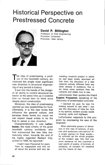
water to the steel. The process mighttake several years, but once corrosion isstarted, failure becomes inevitable.The prestressed concrete pole offersthe following advantages: First; the concrete used is of a quality sufficient toresist penetration of water, otherwisethe pole could conceivably fail duringthe prestressing operation. Secondly, ina prestressed pole, the concrete is usually in compression, and cracking is notpossible except under abnormal conditions of handling or service. Thesecharacteristics give the prestressed polegreater advantages over the normalreinforced pole and are the reasons forthe development and use of prestressedconcrete poles.Today, prestressed concrete poles arewidely used throughout Eastern andWestern Europe. They are extensivelyutilized in Japan and to varying degreesin many other countries around theworld. Available data indicate that theSoviet Union has produced and used themost poles, whereas the United Statesand Canada have only recently initiatedtheir utilization.SCOPE OFAPPLICATIONPrestressed concrete poles have foundincreasingly wide acceptance due totheir viability as a factory produced unit.It is reported that East and West Germany, Poland, and Czechoslovakia eachmanufacture 50,000 to 100,000 poles ayear. In the Soviet Union the annualproduction amounts to several hundredthousand concrete poles. France reportedly uses more than 400,000 concretepoles every year from its 14 factoriesproducing this unit. In Japan, NipponConcrete Industries, the leading manufacturer of spun concrete poles, produces more than 5400 tons (4900 t) ofprestressed concrete poles a month intheir eight factories, In 1979 a group ofAmerican engineers visited a concretePCI JOURNAL/September-October 1984SynopsisPresents an historical and stateof-the-art review of the application,design, manufacture, testing, handling, transportation, and erection ofprestressed concrete poles throughout the world. Particular emphasis isgiven to centrifugally spun precastconcrete poles.Design criteria (especially loadselection) are discussed in detail together with the relevant provisionsfrom the various codes of practice. It isconcluded that prestressed concretepoles will play an increasingly dominant role in the future.pole plant belonging to the ShanghaiElectricity Bureau in China, whichstarted spinning regular reinforced concrete poles in 1958 and prestressedpoles in 1968 (Figs. 1 and 2).In East Germany prestressed concretepoles find application in many fields. Inthe following industries, of the totalnumber of poles, the percentages forprestressed concrete are: for electricpower transmission lines, 60 percent;for overhead wires on railways, 30 percent; for lighting systems, 70 percent;and for other uses, 20 percent.In Norway not many prestressed poleshave been produced for electric powertransmission because the terrain makestheir transportation too difficult and expensive. However, the use of prestressed poles facilitated the electrification of railroads in mountainous areas.In Poland and other Eastern European countries various types of prestressed concrete poles are used fortelephone and electric power transmission lines.In Western Europe spun prestressedconcrete poles are widely used for electric power transmission, railroads,53
Fig. 1. Spun concrete poles (ShanghaiFig. 2. Closeup of spun concrete pole(Shanghai Electricity Bureau).54Electricity Bureau).lighting masts and antennas, and communication masts. The British Railwayshave extensively used prestressed polesfor carrying overhead transmission.Figs. 3-10 show these applications.In the Soviet Union reinforced concrete poles were first used for electricpower transmission lines in 1933. During World War II, reinforced concretepoles began to be used more widely.Many poles were needed on the electricgrid as replacements for those destroyedand for expanding the system. Thegrowth of the precast concrete industryfacilitated the manufacture of thesepoles in various types and sizes.The electrification of the railroadsystem is of great importance to theSoviet Union. Every year about 1250miles (2000 km) of track are electrified,and the use of prestressed concretepoles to carry the overhead cables havebeen a major feature of the work. Theproduction of concrete poles for overhead cables on railroads reached
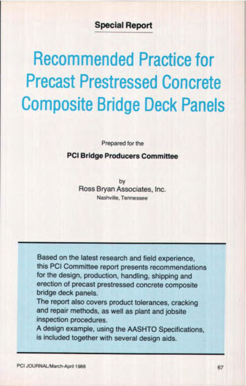
EFig. 3. Railroad electrification structures (Western Europe).Fig. 4. Electric power distribution structure(Western Europe).PCI JOURNAL/September-October 1984Fig. 5. Electric power distribution structure(Western Europe).55
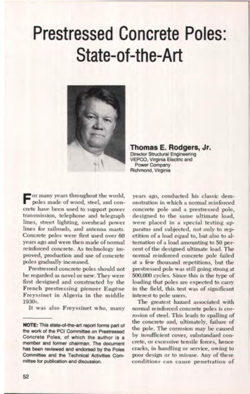
Fig. 6. Electric power transmissionstructure (Western Europe).Fig. 7. High rise lighting structure (WesternEurope).Fig. 8. Street lighting structure (WesternEurope).Fig. 9. Street lighting structure (WesternEurope).56
106,000 units a year in 1959, includingsome 39,000 prestressed units. Sincethen, in order to use less steel but stillincrease the quality of the poles, theproduction of prestressed poles hasgone up and by 1964 they displaced ordinary reinforced concrete poles completely. The annual production of polesfor automatic signaling, telephone systems, and overhead electric powertransmission for railroads is over100,000 units.In Japan there is a nationwide use ofprestressed concrete poles for electricpower transmission, distribution andsubstations, overhead power transmission for railroads, telephone and communication systems, lighting standards,flood-lighting, and wire netting supports. In recent years Japan has becomean exporter of large quantities of poles toall of southeast Asia, in addition to thewest coast of North America (Fig s.11-14).Prestressed concrete poles have a!so been made and used for power distribution in New Zealand, Australia,India, and South Africa since the mid1950s.In the United States reinforced concrete poles were used by some electricutilities in the 1930s, but the first prestressed concrete poles were used byFlorida Power Corporation in 1954when they designed a 66 kV pole and anH-section to use in a 110 kV H-framestructure. By the early sixties, FloridaPower Corporation and Florida Powerand Light Company were using prestressed poles for lighting and powerdistribution. Today, the Florida utilitiesare still using statically cast square prestressed poles for lighting, distribution,and for some transmission up to 230 kV(Fig. 15).In 1962, the Eugene Water and Electric Board of Eugene, Oregon, constructed I mile (1.6 km) of doublecircuit H-frame 115 kV transmission linealong the McKenzie River, using a tapered I-shaped prestressed concretePCI JOURNAUSeptember-October 1984Fig. 10. Communication structure(Western Europe).pole as an aesthetic challenge. Theyhave continued to use the I-shaped prestressed pole as a single circuit pole, andas a single and double circuit H-frametransmission structure (Fig. 16).In 1964, the Virginia Electric andPower Company (Vepco) built its firstprestressed concrete pole structures, atapered I-shaped pole (Fig. 17). Thesepoles were used to rebuild and upgrade,from 34.5 to 115 kV, a 3-mile (4.8 km)water crossing in the coastal area ofNorth Carolina. Each pole was set in apost-tensioned, centrifugally-spun concrete cylinder pile of predetermined57
1-ig.11. Railroad electrification structures (Japan).Fig. 12. Electric power distribution structures (Japan).58
length. The piles were jetted and driveninto the bottom of the Currituck Sound.Vepco in 1966, used a static cast, taperedsquare pole for lighting distribution andsome 115 kV transmission.In 1968 Vepco changed fromstatically cast poles to centrifugallyspun prestressed poles having tapered, hollow, circular cross sections. This type of pole is still beingused for lighting, distribution, transmission, and substation structures.Currently, there are several utilities inthe United States and Canada using anumber of different types and shapes ofprestressed concrete poles for lightingand for power transmission and distribution.Fig. 13. Power transmission structures(built in Japan).Fig. 14. Telephone line structures (Japan).PCI JOURNAL/September-October 198459
AFig. 15. Power transmission structure(Florida Utility Company).--HFig. 16. Power transmission structure(Eugene Water and Electric Board).Fig. 17. Power transmission structure(Virginia Electric and Power CompanyCurrituck Sound Crossing). Built in 1964,these tapered I-shaped prestressedconcrete poles were used to upgrade a34.5 to 11.5 kV, 3 mile (4.8 km) watercrossing in North Carolina. The poles weremanufactured using the centrifugally-spuncylinder pile method.
DESIGN LOADINGSPole structures have to be designed tobe reliable, serviceable, and to resist(without permanent distortion) all anticipated maximum service loads. In theUnited States, the loading conditions forelectric power structures have to meetor exceed those given in the NationalElectrical Safety Code (NESC). Forlighting structures, the loading conditions have to meet or exceed the NESCandlor AASHTO Standard Specifications for Structural Support for HighwaySigns, Luminaires, and Traffic Signals.For microwave or antenna towers, theloading conditions have to meet or exceed the Electronic Industries Association Standard RS-222-C.These loadings are minimum requirements and the designer's study ofthe structure location will determinewhether these minimum requirementsshould be increased. Loads other thanthose required by the codes or standardsthat affect the design of these structuresare those due to extreme weather, or tomanufacturing, handling, transportation,and erection.Electric Power TransmissionStructuresIn these types of structures the designloadings are due to (1) vertical loads, (2)transverse loads, and (3) longitudinalloads.In addition to their own weight,structures are subjected to vertical loadsdue to dead loads of wire and attachments, and ice. The only variable here isthe ice. A structure should be designedfor vertical loads due to maximum vertical span, ice, construction, and maintenance loads.The maximum vertical span dependson the terrain. Structures located onhills must support more wire load, lowpoint to low point of wire sag, than theadjacent structures which are located onlevel ground (Fig. 18). The horizontalPC! JOURNALISeptember-October 1984wind span is unaffected by terrain andwill always he half the true horizontaldistances between suspension structures.Selection of the ice loads should bebased on experience records for eachservice area; these records can be obtained from the U.S. Weather Bureau.Ice build-up may not be the same on allspans, and the engineer should recognize this effect when designing for unbalanced longitudinal loads.During the wire stringing operation,the structure may receive vertical loadsmore severe than those in normal designloadings.For maintenance loads, the structureshould be designed to provide adequatesupport for conductors that are beinglowered during a repair operation. Thisis often overlooked and could be a critical factor for a light structure.Transverse loads are caused by (1)wind pressure on the structure andwires and (2) the transverse componentof line tension at angles. In combiningthese loads to give a total transverse design loading, it is important to ensurethat the appropriate conductor tensionbe used with the corresponding windload.Extreme wind forces on transmissionlines may be caused by three fundamentally different types of meteorological systems: (1) tornadoes, (2) hurricanes, and (3) local thunderstorms.A tornadic wind is a type of awhirlwind with rotating wind velocitiesestimated at well over 200 mph (322kmlh). Tornadoes have velocities andaccompanying pressures so great thatthey destroy everything before them,but fortunately they take narrow pathsand, as a rule, do not last long. Reportedlosses of transmission structures in atornado are usually small, typically onlyone to six structures for each strike. Engineers generally agree that it is uneconomical to design structures to resisttornadoes.A hurricane is a very violent61
VV IV2VERTICALSEMISPANSFig. 18. Vertical and horizontal design spans for pole structure,windstorm out of the West Indies; thesewindstorms usually blow up in summerand fall of the year. On the Beaufortscale, winds of over 75 mph (121 krn/h)are classed as hurricane winds. Thestorm usually starts as a tropical depression in the Atlantic Ocean. As it movesalong its path, the counter-clockwisewinds around the center grow in intensity in the area covered. Winds of 100 to120 mph (161 to 193 km/h) are common,Hurricanes cause great destruction eachyear to parts of the Caribbean Islands,Gulf, and East Coast States. In thePacific Ocean, these storms are calledtyphoons. Engineers in the areas affected by hurricanes have to pick a design for extreme wind speed that is abalance between risk of failure andstructure cost.Thunderstorms and squall lines aremore localized and random in their impact and are the main concern of engineers in most parts of the country.To determine the design wind load,the engineer needs to know a designwind velocity and a suitable equation bywhich it can be converted to pressure onthe transmission line. The design windloads may be determined for a geograph62ical area by using the annual extremefastest-mile wind charts developed bythe U.S. Department of Commerce—Environmental Science Service Administration using statistical probability.Charts are available for elevations of30, 60, and 90 ft (9, 18, and 27 m) aboveground, in varying mean-recurrenceintervals. To realize what these chartsare, consider the wind velocity record ofFig. 19. It represents a 5 minute windvariation at the location of a certainstructure during the most severe stormof a given year.The 5 minute average and the peak2-second gust are self-explanatory. Thefastest mile is defined as the averagevelocity at which 1 mile (1.6 km) of airpasses the anemometer.The operational life of the transmission line should determine the mean recurrence interval chart that is used.Utilities normally consider the life of awood pole line at about 25 to 30 years,steel and prestressed concrete structurallines at about 60 years. It is recommended that a 50-year mean recurrenceinterval be used for prestressed concretestructure lines.
VELOCITY AT AIPEAK GUST OF 2Sv—FASTEST MILE OR IM vOII11141 1-5 MIN.I MIN.Fig- 19. Wind velocity strip graph for designing pole structure.A well-known formula for increasingwind speed according to height is:) lInV V hn 0(1)whereV,, adjusted velocity, mphV. annual extreme fastest milewind chart velocity, mphh adjusted elevation, ftho elevation ofVa , ftn constant dependent on surfaceroughness (varies from 2 to 7)A value of 7 for n is normally used forlevel or slightly rolling land with scattered trees or buildings. The formula isnot reliable for use in decreasing windspeeds below 30 ft (9 in). Wind velocity,in mph, may be converted into windpressure by using the following formula:For wind pressures on cylindricalsurfaces:P 0.0025 V (2)For wind presures on flat surfaces:P 0.0042 V 2(3)whereP wind pressure, psf, on projectedarea of surfaceV design wind velocity, mphPCI JOURNALJSeptember-October 1984Wind Pressure on StructuresThere appears to be general agreement that short wind gusts are largeenough to envelop a transmissionstructure. For this reason, the designwind pressure on a transmission structure should be determined from a gustvelocity. Relationships between peakgust and fastest mile have been developed; one such expression used bythe industry is:Peak gust 1.3 x Fastest mile (4)To find the design wind pressure on atransmission structure, the wind pressure formula should be adjusted to:P k (1.3V)2(5)where k is the surface shape coefficient.The same problems of selecting windvelocity and suitable equations alsoarise with regard to the transmissionline. It has been mentioned that a shortgust of wind could envelop a structure,but it cannot envelop a span oftransmission line approximately 1000 ft (305 m)in length. Field tests have shown that areduction factor can be applied to modify the conventional drag coefficients inpicking a wind pressure on a conductor.After the conductor design pressure has63
been determined, an effective windspan factor (fP,,) of 0.6 should beapplied to all spans in excess of 1000 H.For span lengths between 300 and 1000R (91 and 305 m), this factor will varyand should be determined as follows: 1.0 – 0.4 (S – 300)/700 (6)where S is the span length, ft.For spans of 300 ft (91 m) or less, theeffective wind span factor should be 1.0.Extreme wind with heavy ice isanother condition the engineer has toconsider. Maximum winds that occurduring sleet storms are usually lower inintensity than winds at other times inthe same area. The engineer must review local weather records to determinethe range of wind velocities that occurduring freezing precipitation. Then,using the appropriate ice loading, hemust calculate whether the wind-withice condition is more critical as a transverse load than the higher wind on bareconductors.A study made in Canada of maximumwind recorded during freezing precipitation and for one day after, tabulatedlocal variation. This technique is valuable for the engineer because data canbe taken directly from weather records,thus showing winds which are likely tooccur in a given area when there is iceon the conductor.Transverse Loads and Line AnglesThe transverse loading upon thestructure must be taken as the resultantload equal to the vector sum of thetransverse wind load and the resultantload imposed by the wires due to theirchange in direction. In deriving theseloadings, a wind direction must be takenwhich will give the maximum resultantload. Proper reduction is made in loading to account for the reduced windpressure on the wires resulting from theangularity of the application of the windto the wires.64In areas of moderate to heavy iceloadings, this transverse component willtend to control the design of angle anddead end structures. In areas of no ice,or where only minor icing occurs, careshould be taken in determining the effect of wind on line tension, being sureto use the same design wind velocity tocalculate line tension as is used to calculate the strength of the structure. Careis necessary also in calculating which ofthese two "maximum" conditions iscritical:1. Maximum wind velocity with corresponding line tension2. Maximum line tension with corresponding wind velocityLongitudinal LoadingFor years, transmission structureshave been designed using a longitudinalloading condition of a broken conductorand/or overhead shield wire dead load.In recent years, the trend has been touse larger conductors, and many utilitieshave regarded the broken wire condition as being too conservative.Longitudinal loads can he imposed onstructures by many conditions otherthan broken wires. The following areseveral other conditions under which astructure will he subjected to longitudinal loadings:1. Conductor or overhead shield wirestringing loads2. Unequal spans3. Wind parallel to the line4. Wind at 45 deg to the line5. Ice-unloading unbalance6. Loss of an adjacent structureDuring stringing operations there areinstances where the stringing block mayjam momentarily, or a sleeve passingthrough the block may "hang up,"causing some longitudinal load to beapplied to the structure. Stringingequipment located too close to a structure may impose detrimental verticaland longitudinal loads to the structureduring wire stringing operations.
Table 1. Overload capacity factors for metal and prestressedconcrete structures (NESC Table 261-2).Overload capacity factorsStrengthGrade BGrade CVertical strengthTransverse strengthLongitudinal strengthAt crossingsIn generalAt dead endsElsewhereIn generalAt dead ends1.502.502.201.101.65No requirement1.101.10No requirement1.651.101.10Note: The factors in this table apply for the loading conditions of NESCRule 250B. For extreme wind loading conditions, Sec NESC Rule 260C.In mountains or very hilly areas, it ispossible to have longitudinal loadscaused by unequal spans. This is due tothe difference in tension in the wires inadjacent spans resulting from unequalvertical loading and/or unequal spanlength.Winds not only blow on the structuresin the transverse direction, but in thelongitudinal direction and at all anglesin between. The structures should at aminimum be designed to withstand thewind plus gust which may envelop it inthe longitudinal direction. Windsblowing at 45 deg to the line can exertlongitudinal forces on the structure dueto wind on the wires and wind on the,,tructure itself. These longitudinalforces should be investigated.Ice -unloading unbalance is now themost commonly used longitudinalloading. The dropping of ice from one ormore wires in different combinations isused by a designer to provide torsionalstrength in addition to longitudinalstrength in a structure.Ice may build up on wires in only afew spans causing longitudinal loads. Inmost cases, ice builds fairly uniformlyon all spans, and usually drops from onespan before another. Ice frequently fallsin large chunks when it starts to melt. AsPCI JOURNALJSeptember-October 1984these chunks fall from one span, theswing of the insulator strings in a longitudinal direction is noted. This has leddesigners to use only a percentage of theice-no-ice tension differential as thelongitudinal loading. The longer the insulator string, the more the tension differential is reduced.Under Section 25, the NESC sets theminimum weather loading condition forwhich a transmission line is to he designed. These minimum weather loadings must be values of loading resultingfrom the application of Rule 250-B Combined Ice and Wind Loading orRule 250-C — Extreme Wind Loading,whichever is the greater.In the design of pole structures, theterm "overload capacity factors" is interpreted to mean that the structureshould support, without permanent set,the maximum loadings to which it willbe subjected multiplied by the appropriate overload factors,The general loading requirements setforth in Section 25 of the NESC are to bemultiplied by overload Factors set forthin Section 26, "Strength Requirements"depending on type of structure, to establish the design loads (see Table 1).The minimum strength of any polestructure must be sufficient to with65
The following loads are typical ofthose usually considered:T HifHz1f1T2Fig. 20. Line angle loads actingon pole structure. Note:Line angle load H, HZ.stand, without conductors, the extremewind pressure in Rule 252 applied inany direction of the structure, multiplied by an overload capacity factor of1.0. A gust factor appropriate for thewind pressure and structure heightshould be considered.The overload factors for prestressedconcrete pole structures as set forth inSection 26 of the NESC are shown inTable 1.The transmission line designer, as canbe seen, starts with the NESC recommended load schedule for geographicarea in which the line will be built.Following this procedure, combinationsof wind, ice and dead loads are addedbased on local weather conditions, pastexperience, and historical precedence.To each of the contingencies, overloadfactors are applied to weigh the importance of that particular contingencyunder the site's unique conditions.The designer of the structure, mustexamine all these loading conditions,since different loads will control individual members or sections of the finished structure design.For design purposes, all wire loads ona transmission structure are consideredto be concentrated loads with a transverse, longitudinal and vertical component.661. Vertical LoadsA. Weights of bare wires plus insulators at attachment pointsB. Weights of wires coated withradial in. (13 mm) ice plus insulators at attachment pointsC. Weights of wires coated with 1 in.(25 mm) radial ice plus insulatorsat attachment pointsD. One man plus equipment at critical pointsE. Vertical components of stringingloadsLoads A, B, and C are calculated asthe product of the weight of wires(coated or not) per unit length by thevertical span V.2. Transverse Loads (Fig. 20)F. Line angle loads from bare wiressubjected to extreme wind, fastestmile at 60F(16C).G. Line angle loads from Vs in. (13mm) ice coated wires subjected to40 mph (64 km/h) wind at 0 F (-18C) [4 psf (0.19 kPa) wind prssure]H. Line angle loads from wirescoated with I in. (25 mm) ice at 0 F(-18 C)I. Transverse force on structure dueto 40 mph (60 km/h) wind [6.4 psf(0.3 kPa) wind pressure IJ. Transverse force on structure dueto extreme wind (say 1.3 x fastestmile)K. Transverse forces at attachmentpoints due to 40 mph (64 km/h)wind on wires coated with 1 in. (25mm) iceL. Transverse forces at attachmentpoints due to extreme wind (say1.3 x fastest mile) on wiresM. Transverse component of force onstructure due to diagonal extremewindLoads F, G, H, and I can be determined as algebraic sums of the trans-
verse components of tensions of attached wires.Note that transverse forces K and Lare the products of wind forces per unitlength of wire by appropriate windspans.3. Longitudinal LoadsN. Unbalanced wire tensions due tounequal vertical loads, differentspan configurations, etc.0. Longitudinal force on structurefrom extreme wind (say 1.3 x fastest mile)P. Longitudinal component of forceon towers from diagonal extremewindQ. Longitudinal component ofstringing and construction loadsR. Broken wires — Loads should reflect experience under actuaI conditionsS. Ice-unloading unbalance — Iceno-ice tension differential x percent reduction due to insulatorswingT. Dead-end tensions from bare cables subjected to extreme wind at60F(16C)U. Dead-end tensions from ;/s in. (13mm) ice coated wires subjected to40 mph (64 km/h) wind at 0 F (-18C)V. Dead-end tensions from 1 in. (25mm) ice coated wires at 0 F (-18C)Design loads for prestressed concretestructures are ultimate loads. The following design loading conditions, loadmultiplied by overhead capacity factor,can be used at overhead shield wire andconductor points:NESC — Heavy LoadingCase I 1.50 (B)2.50(K) 1.65 (G)(Vertical load)(Transverse load)Extreme windCase II 1.50 (A)(Vertical load)1.1 (L) 1.1 (F)(Transverse load)PCI JOURNAL/September-October 1984vs-- Tsfr çL v—W--r TVT transverse loadL longitudinal loadV vertical loadw wind on structureV, . L, T, shield wire loadsFig. 21. Design loads ("load tree")acting on pole structure.Heavy Ice1.1 (H)Case I11 1.50 (C)(Transverse load)(Vertical load)1.1(S)(Longitudinal load)The above are the basic loading cases.This is the procedure the utility engineer goes through in supplying thedesigner with the "load trees" (Fig. 21)required to design prestressed concretepole structures.Lighting StructuresLighting pole structures must meet orexceed the design loadings of the NESCand/or AASHTO Standard Specifications for Structural Supports for Highway Signs, Luminaires and Traffic Signals, and include (1) dead load, (2) liveload, (3) ice load, and (4) wind load.In addition to its own weight, thedead load includes all permanently attached fixtures, including hoisting de67
vices and walkways provided for servicing of luminaires, if required.Live load need not be applied tostructural supporting members. Theonly member requiring a live load design would be the walkway and ladders.The ice load of 3 psf (0.14 kPa) isapplied only to the attached fixtures,ladders, walkways, luminaires or signs,and is based on 0.50 in. (13 mm) of ice at60 pef (961 kg/ms).Wind speeds are based on the 25-yearmean recurrence interval wind speedmaps developed by the U.S. Department of Commerce — EnvironmentalScience Service Administration andadjusted for height. Wind pressure onstructural supports is computed from:P 0.00256 (1.3V)2 C d C,(7)whereCd a dimensionless drag coefficient that varies with the shapeof the support structure receiving the wind loadingC„ coe
and Light Company were using pre-stressed poles for lighting and power distribution. Today, the Florida utilities are still using statically cast square pre-stressed poles for lighting, distribution, and for some transmission up to 230 kV (Fig. 15). In 1962, the Eugene Water and Elec-tric Board of Eugene, Oregon, con-structed I mile (1.6 km) of .