Transcription
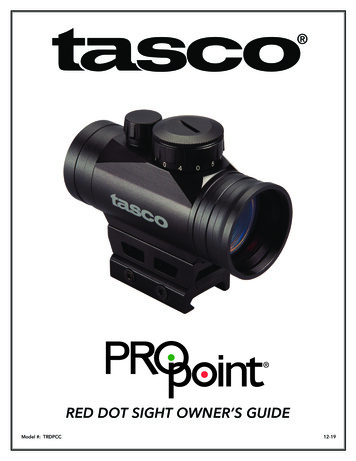
MICRO GREEN DOT with INTEGRATED RED LASERThe Patented Micro Green Dot with Integrated Red Laser is a compact optical system packed withmany features. The Green Dot is designed as the primary targeting system and the Red Laser as asecondary targeting device. You may use the Green Dot or Red Laser individually or you have the optionto use both the Green Dot and Laser at the same time. The Red Laser can be used for quick point shootingwith targets close to the shooter. The Micro Green Dot and Red Laser combo will mount to nearly anyWeaver/ Picatinny type rail.Backed by America’s Best Warranty, your VISM Optic will provide you with years of reliableservice. This Owner’s Manual will help you understand all of the features of your new Dot Sight. Pleasefollow all instructions carefully before initial use to experience the best results.Features: Green LED (Light Emitting Diode) dot reticle is 100% safe for the eyes.Unlimited eye relief.Compact Optic Design.Green Dot Reflex Optic that is fully adjustable for Elevation & Windage.Five brightness settings for the Green Dot Sight.Integrated Red Laser sight that is fully adjustable for Elevation & WindageAbility to use Green Dot or Red Laser Individually, or Both at the same time.Integrated rail mount for mounting onto Weaver/ Picatinny type railsVDGRLB (Black model) - Black anodized aluminum construction.VDGRLT (Tan model) - Tan powder coated aluminum construction.Mounting the OpticThe optic’s mount is the link between your firearm and your optic. It is very important to have asolid connection between the two in order to ensure proper function of all components. VISM has madeinstallation of your optic easy by incorporating the Weaver/Picatinny type mount into the Green Dot MainBody.This optic’s low profile mount is suitable for firearms with a stock that has a cheek rest that dropsdown below the firearm’s optics rail. If you’re using this on a firearm with the stock and cheek rest at the
same plane as the firearm’s optics rail (such as an AR15 platform) we recommend the use of a riser mount.A ¾” riser mount is recommended for the AR15 platform. NcSTAR and VISM have several riser mountoptions available. Please visit our web site to view the available mounts: www.ncstar.comYou should place your firearm on a secure platform, such as a gun vise, before performing any of thefollowing procedures.CAUTION: CAREFULLY FOLLOW ALL OF THE MOUNTING PROCEDURES. FAILURE TO DO SO CANCAUSE DAMAGE TO YOUR SIGHT OR FIREARMCAUTION: BE SURE THAT YOUR FIREARM IS UNLOADED AND POINTED IN A SAFE DIRECTION.PRACTICE SAFE FIREARM HANDLING PROCEDURES AT ALL TIMES.1. Begin by loosening the Mount Allen Head Bolt on the left side of the Main Body. Using the provided3mm Allen Wrench, turn the Allen Head bolt in the Mount Counter-Clockwise ( ) to loosen Rail Clampfrom the mount.2. After loosening Allen Head Bolt, push in the Allen Head Bolt inwards towards the mount, this will pushthe Rail Clamp away from the mount. This will allow you place the Green Dot directly onto the opticsrail of your firearm. Seat the Green Dot sight onto the top of your firearm’s optics rail, with theObjective Lens (Platinum coated lens) facing the muzzle. Make sure that the Allen Head Bolt on thebottom of the Mount fits securely into a cross slot on your firearm’s optics rail. Once you have yoursight positioned properly, turn the Allen Head Bolt Clockwise ( ) until the Rail Clamp secures theGreen Dot sight to the firearm’s optics rail.3. You have now successfully mounted your sight.Dismounting the Optic1. Begin by loosening the Mount Allen Head Bolt on the left side of the Main Body. Using the provided3mm Allen Wrench, turn the Allen Head bolt in the Mount Counter-Clockwise ( ) to loosen Rail Clampfrom the mount.2. After loosening Allen Head Bolt, push in the Allen Head Bolt inwards towards the mount, this will pushthe Rail Clamp away from the mount. This will allow you remove the optic from the rail.OperationThe Rheostat Knob performs a number of functions. The Rheostat Indicator Marking is printed andlocated on the top of the Main Body with a White Dot. There are Numbers and Letters printed on the edgeof the Rheostat Knob. The Rheostat Knob is the ON/OFF switch for both the Green Dot Sight and the Red Laser Sight. TheGreen Dot and Red Laser will be in the OFF position when the Rheostat Knob is set to the Number“0”.
The Numbers “1-5” are different brightness settings for the Green Dot, in which “1” is the dimmestsetting and the higher numbers increases the brightness level of the Green Dot. Number “5” is themaximum brightness level for the Green Dot. The Letter “L” (for ‘Laser’) on the Rheostat Knob will turn ON the Red Laser Only. The letter “B” (for ‘Both’) will allow the user to turn BOTH the Green Dot sight and Red Laser ON atthe same time. After you are done using the optic make sure that the Rheostat Knob is set to “0” (OFF position) inorder to preserve battery life.Zeroing Your Green Dot SightAdjusting the Green Dot Windage and Elevation:The Green Dot optic equipped Windage and Elevation Turrets. The Elevation Turret is located ontop of the Main Body. First remove the Turret Cap Counter-Clockwise ( ) from the Elevation Turret anduse a flat blade screwdriver or coin to make elevation adjustments. Turning the Green Dot Elevation Turret Clockwise ( ) will move the Green Dot Up ( ), moving theBullet Impact Down ( ).Turning the Green Dot Elevation Turret Counter-Clockwise ( ) will move the Green Dot Down ( ),moving the Bullet Impact Up ( ).The Windage Turret is located on the Left side of the Main Body. First remove the Turret CapCounter-Clockwise ( ) on the Windage Turret and use a flat blade screwdriver or coin to make windageadjustments. Turning the Green Dot Windage Turret Clockwise ( ) will move the Green Dot to the Left ( ), movingthe Bullet Impact Right ( ).Turning the Green Dot Windage Turret Counter-Clockwise ( ) will move the Green Dot to the Right( ), moving the Bullet Impact Left ( ).Reinstall both of the Turret Caps Clockwise ( ) once you have made all necessary adjustments.NOTE: Each click of adjustment changes the point of impact (where the bullet strikes the target). Thismeans that adjusting in direction of the markings on the Windage Turret stating L will move the pointof impact to the Left ( ). This also means that adjusting in direction of the markings on the ElevationTurret stating UP will move the point of impact Up ( ). Each click will move the Green Dot by theamount shown on the chart below.Windage/Elevation inches of movement per click25 yards50 yards75 yards100 yards200 yards1/4”1/2”3/4”1”2”
Sighting In Your Green Dot Sight:After you have completed installation of your Optic it will be necessary to adjust the Optics point ofaim to match the rifles point of impact. This can be accomplished using several methods, but werecommend the use of a Bore Sighting Device to save time and ammunition. Using a Bore Sighting Devicewill ensure that your shots land “on paper”. Follow the Manufacturer’s Instructions for the Bore SightingDevice that you choose in order to achieve the best results. You are now ready to finalize your Zero.CAUTION: ALWAYS BE SURE TO REMOVE THE BORE SIGHTING DEVICE BEFORE SHOOTINGLIVE AMMUNITION. FAILURE TO DO SO CAN CAUSE DAMAGE TO YOUR FIREARM ORINJURY TO YOURSELF AND THOSE AROUND YOU.CAUTION: WHEN OPERATING ANY TYPE OF FIREARM ALWAYS USE PROPER EYE ANDEAR PROTECTION. BE SURE TO USE YOUR FIREARM IN AN AREA THAT IS PERMISSIBLEUNDER LOCAL, STATE, AND FEDERAL LAW.Bore Sighting alone is not sufficient enough to ensure an accurate Zero. You must shoot youfirearm at the range in order to confirm a 100% accurate Zero. Follow these steps to fine tune your Opticadjustments:1.2.3.4.5.Secure your firearm using a steady platform such as a rifle bench rest or sand bags.Fire 3 to 5 carefully aimed shots at a target that is set to your desired Zeroing distance.Observe where the bullet grouping has struck the target and make adjustments to the Elevation andWindage settings as necessary until your point of aim matches your point of impact.Continue with this process until you have achieved your desired level of accuracy.Your Optic is now Zeroed to your firearm at the distance that you have chosen.It is important to remember that many factors can affect the accuracy of your optic’s zero includingtemperature, humidity, elevation, distance, angle, and other conditions. Changing ammunition brands canaffect accuracy as well.CAUTION: AVOID DIRECT EYE EXPOSURE TO LASER BEAM!Zeroing Your Red Laser SightAdjusting the Laser Windage and Elevation:The integrated Red Laser on your optic is adjustable for both Elevation and Windage. The LaserWindage Adjustment Set Screw and Laser Elevation Adjustment Set Screw are both found on the RedLaser Housing located at the very top of the Main Body, and can be adjusted by using the provided 1.5mmAllen Wrench. To adjust the Laser Elevation Up ( ), turn the Laser Elevation Adjustment Set Screw Clockwise ( ).To adjust the Laser Elevation Down ( ) turn Laser Elevation Adjustment Set Screw CounterClockwise ( ). To adjust the Laser Windage Left ( ), turn the Laser Windage Adjustment Set Screw Clockwise ( ).To adjust the Laser Windage Right ( ), turn the Laser Windage Adjustment Set Screw CounterClockwise ( ).
NOTE: For zeroing/sighting in your Red Laser Sight, please use the same instructions above titledSIGHTING IN YOUR GREEN DOT SIGHT.Battery InstallationYour Green Dot with Integrated Red Laser optic comes ready to use with a pre-installed CR2032battery from the factory. If the battery life expires or your optic or laser no longer illuminates, follow thesesimple instructions:1. The Battery compartment is located within the Rheostat Knob.2. On the top of the Rheostat Knob you will notice a thin Battery Cap. To remove this Battery Cap graspthe knurled edge of the Battery Cap firmly with one hand and twist it off Counter-Clockwise ( ), whileholding the Rheostat Knob firmly in place with the other hand.3. Remove the old battery and dispose of it properly. Replace it with a new 3 volt Lithium Battery typeCR2032 only. Place the new CR2032 Battery in the Battery Compartment with the Positive “ ”terminal facing out towards the Battery Cap. Twist the Battery Cap Clockwise ( ) back onto theRheostat Knob and hand tighten. Avoid using tools (such as pliers) to perform this procedure as thismay cause damage to the unit.NOTE: If the Green Dot reticle functions, but the Red Laser does not turn On, then the Battery may nothave enough charge to power the Red Laser. The Red Laser requires more energy to activate than theGreen Dot reticle. Replace the battery with a brand new CR2032 Battery for the Red Laser to function asnormal.Care and MaintenanceYour VISM Dot Sight is a factory sealed unit, please do not attempt to take it apart or clean itinternally. The exposed optical lens surfaces will perform their best if they are routinely cleaned with a lensbrush and the lens cloth provided with your sight. For a deep cleaning, you can also use high qualitycamera lens paper and camera lens cleaning solutions. Never use any other type of materials or solventsother than those designed specifically for optical lenses to avoid damaging your sight. Clean the outer edgeof the lens cavity first with cotton swabs, clearing as much debris and dust as possible. Then, gently cleanthe lenses using a circular motion starting in the center and ending at the edges. Do not rub the lensescontinually; simply wipe in small circular patterns. Maintain the exterior surfaces of the scope by removingdirt or sand by using a soft brush or a soft dry cloth. You can also use a silicone treated cloth to restoreluster of the optics body and protect the scope against corrosion. Be careful not to touch any of the lenseswith the silicone cloth. When not in use, always store your sight in a dry place with lens covers on toprevent scratches to the lenses.
IF YOU ARE UNFAMILIAR WITH ANY OF THE PROCEDURES IN THIS MANUAL, ALWAYS SEEKTHE HELP OF A QUALIFIED PROFESSIONAL TO AVOID DAMAGE TO YOUR DOT SIGHT AND YOURFIREARM.Specifications:GREEN DOT REFLEX OPTIC: OBJECTIVE LENS DIAMETER: 25MMMAGNIFICATION: 1XRETICLE: GREEN DOTDOT SIZE: 3 MOACLICK VALUE: 1 MOALENS COATING: PLATINUMBATTERY TYPE: CR2032 ooLENGTH: 2.44” (2.64” WITH LENS COVER)WIDTH: 1.67”HEIGHT: 1.90”WEIGHT: 4.0 OZ.BODY COLORS:VDGRLB – BLACK ANODIZEDVDGRLT – TAN POWDER COATINGRED LASER: LASER CLASS: CLASS IIIa LASER WAVELENGTH: 635-655nm MAXIMUM OUTPUT POWER: 5mWNOTE: The Objective Lens (Platinum coating) is angled by design from the factory. It is not amanufacturing defect. The Objective Lens is engineered at the proper angle to reflect LED Dot Reticle(which is projected from the side of the optic’s body) back to the shooters eye centered in the lens and scopebody when viewed from the Ocular Lens.US PATENT: D679,775
Green Dot and Red Laser will be in the OFF position when the Rheostat Knob is set to the Number "0". The Numbers "1-5" are different brightness settings for the Green Dot, in which "1" is the dimmest setting and the higher numbers increases the brightness level of the Green Dot. Number "5" is the


