Transcription
Installation description EB06Boat engines fromVOLKSWAGEN MarineDesign and functionTDI 225-6TDI 265-6
ForewordThis installation description explains theprocedure for installing all 6 cylinderVOLKSWAGEN Marine boat engines.General Products, that are lot listed in this installationdescription but which are neverthelessrequired, should only be sourced from specialistsuppliers. The professional installation of this engine andits component parts is very important to makesure all components function correctly togetherin a fault-free manner.Therefore all work must be carried out with theutmost care.EB6-0009NEWThis installation manual includes the designPlease see the relevant KD literature for the latest testing, adjustmentand functioning of new developments!and repair instructions!The contents will not be updated.ImportantNote
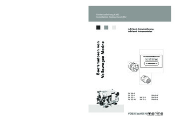
ContentsForeword . . . . . . . . . . . . . . . . . . . . . . . . . . . . . . . . . . . . .2Installation instructions . . . . . . . . . . . . . . . . . . . . . . . . . .4Exhaust system . . . . . . . . . . . . . . . . . . . . . . . . . . . . . . . .6Unit mounting / engine mounting . . . . . . . . . . . . . . . . .8Electrical system . . . . . . . . . . . . . . . . . . . . . . . . . . . . . . 10Connections to the engine . . . . . . . . . . . . . . . . . . . . . . . . . . . . . . . . . 10Instrumentation . . . . . . . . . . . . . . . . . . . . . . . . . . . . . . . . . . . . . . . . . . . 13Overview of instrumentation installation . . . . . . . . . . . . . . . . . . . . . 15Overview of standard instrumentation installation (optional) . . . 18Engine installation dimensions . . . . . . . . . . . . . . . . . .22Engine with Z-drive installation dimensions. . . . . . . .23Engine with reverse gear unit installationdimensions . . . . . . . . . . . . . . . . . . . . . . . . . . . . . . . . . . .25Cooling system . . . . . . . . . . . . . . . . . . . . . . . . . . . . . . .27Engine cooling circuit. . . . . . . . . . . . . . . . . . . . . . . . . . . . . . . . . . . . . . 27Sea water / fresh water circuit . . . . . . . . . . . . . . . . . . . . . . . . . . . . . . 27Fuel system . . . . . . . . . . . . . . . . . . . . . . . . . . . . . . . . . . 31Functional description of the fuel system . . . . . . . . . . . . . . . . . . . . . 31Engine compartment ventilation . . . . . . . . . . . . . . . . 34Engine components list . . . . . . . . . . . . . . . . . . . . . . . . .35Technical Data . . . . . . . . . . . . . . . . . . . . . . . . . . . . . . . 38Installation dimensions for customizedinstrumentation . . . . . . . . . . . . . . . . . . . . . . . . . . . . . . 40Installation templatefor standard instrumentation . . . . . . . . . . . . . . . . . . . . 41Superior3Technology
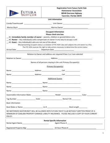
Installation instructions To lift the VOLKSWAGEN Marine boat engineout of its transport container, the threesuspension chains or belts must be inserted inthe suspension eyes provided (see figure).An engine hoist and suitable suspension deviceshould be used. When installing or removing theVOLKSWAGEN Marine boat engine, thesuspension eyes provided on the engine (seefigure) are to be used.Note:When removing the VOLKSWAGEN Marine boatengine from the transport container, make surethat the positioning device for the design cover(see -arrow-) is not damaged by the suspensionchains or belts thus creating a risk of breakage.Properly attach the suspension chains or belts tothe engine in order to avoid the risk of damage. Choose the engine installation location andcompartment so that engine maintenance workmay be easily carried out.EB6-0002 Make sure that when installing or removing theengine, there is sufficient free space.Qualified specialists of the VOLKSWAGEN Marine team are at yourdisposal if you have specific questionsor require technical informationrelating to the installation of theVOLKSWAGEN Marine boat engine.Adjustment of the throttle bowden cableon the sender for throttle lever positionAdjust the throttle bowden cable so that there is adifference of 65 mm between idling and fullthrottle positions (see figure).NoteTo achieve full engine output, the setting of thethrottle lever position sender must be strictlyobserved. After the engine has been started, thevalue of of the throttle lever position (pedalposition sender) can be indicated from 1 - 101% bymeans of the multifunction display enabling you tocontrol engine performance. Instructions on theoperation of the multifunction display areprovided in the "Additional operating manual ofthe multifunction display".SuperiorEB5-00974Technology
Operation with battery isolating diodesRetrofitting of a reverse gear unit to theVolkswagen Marine boat engine Operation with battery isolating diodesis not permitted. When retrofitting a reverse gear unit, variousdetails must be observed and componentsexchanged. Please contact yourVOLKSWAGEN Marine dealer for advice. Always use a battery isolation relay. If in doubt,please contact your nearest VOLKSWAGENMarine dealer. For connection of a gearbox neutral positionswitch (engine with reverse gear unit)see page 12.Connection of a hot water boiler If you wish to install a hot water boiler, pleasecontact your nearest VOLKSWAGEN Marinedealer.Operating an engine with a reverse gear unit Observe the instructions in your instructionmanual!Propeller model drive When selecting a propeller, ensure that theengine can attain the nominal rotation speed inall operating modes.If you do not observe the installationguidelines, your VOLKSWAGENMarine boat engine may be damaged.Superior5Technology
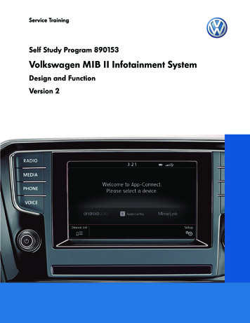
Exhaust systemIntroductionVOLKSWAGEN Marine boat engines are operated using wet exhaust systems.After the exhaust gas collector or turbocharger, the exhaust flow is diverted by the exhaust pipe connection.See water / freshwater is sprayed into the exhaust gas within this exhaust pipe connection.NoteThe water collector (item 5. in the figure) should be dimensioned so that it can accept the total amountof seawater / freshwater that can flow back.The seawater / freshwater mixes with the exhaust gases, cooling them considerably so that in the remainderof the exhaust system, connection hoses made from rubber and PVC parts, capable of withstandingtemperatures up to at least 200 C, can be used.Overview of the exhaust system installation23456785 cm15 cm191110EB6-0022Legend1. Seawater / freshwater filter2. Engine3. Ventilation unit (fit at least 15 cm abovethe water line)4. Exhaust pipe5. Water collector6. Silencer7. Water line8. Swan-neck throat (the lower edge of theexhaust gas pipe at the transom outlet must beat least 5 cm above the water line)9. Transom outlet10. Intake cap11. Sea water / fresh water valveSuperior6Technology
Note The complete exhaust system should beinstalled with as few pipe bends as possible. A minimum pipe cross section* of 100 mm mustbe maintained. Hose connectionsshould always be securedwith double hose clips. Hose connections and rubber sleeves must betemperature-resistant.EB5-0005The exhaust system should not be made too long,to ensure that the correct maximum value for theexhaust gas counter pressure is not exceeded.21 TDI 225-6 at 165 kW max. 350 mbar TDI 265-6 at 195 kW max. 350 mbar3EB6-0001LegendThis value should not be exceeded.1. Screw plug for seawater / fresh waterextraction and connection of the temperaturesensor (optional)2. Screw plug for exhaust gas extraction3. Exhaust gas outletSuperior7Technology
Unit mounting / engine mountingInstructions for installation of the unitmounting1 Do not tension the unit mounting when fitting it.To do so may result in severe vibration anddamage.23 After installation and alignment of the engine,ensure that no residual tensions exist in thedrive train and the unit mountings. Only use original VOLKSWAGEN Marine unitmountings. The securing screws for the unit mountingon the hull of the boat must be provided withwashers.4ProcedureCentre and incline the engine to the appropriateheight using the height adjuster (see item 3.in thefigure) on the unit mounting. Ideally, centring willbe in the middle of the height adjustment range.EB6-0015After aligning the engine, uniformly tighten thesecuring nuts (see figure, item 1) on the unitmountings to a torque of 105 5 Nm.Legend1.2.3.4.Securing nut: 105 5 NmWasherHeight adjusterUnit mounting with base plateTo prevent sideways turning or twistingduring tightening, the height adjuster arrow- of the unit mounting / enginemounting must be held (turned in theopposite direction) with a suitable tool(e.g. an open-ended spanner).To secure the base plate to the boat’shull, use securing screws with suitablewashers.EB6-0021Superior8Technology
Unit mounting dimensionsSide view4123110812EB6-0016Unit mounting dimensionsPlan y
Electrical systemConnections to the engineScrew in the multiway connector -A- to the enginecentral electrical system and the starter unit / relaybox in the direction indicated by the arrow untilthe end ratchet connection is felt and the plug issecurely connected.ANoteUse the wiring harness tool, T 01906, to loosen andtighten the multiway connector.EB6-0032Battery connectionAssemble the battery positive and earth cables forpower supply to the engine with suitable 8 mmring terminals.The cable cross section should be at least 35 mm2for a cable length of up to 4 meters. If a cablelength of longer than 4 meters is required,increase the cable cross section to at least50 mm2.EB5-0013When fitting the ring terminals to thecable ends (35 mm2) of the batteryconnection cables, ensure theseare correctly fitted with a crimpconnection.Superior10 Technology
Battery positive cableConnect the battery positive cable from thebattery to the starter -1- (terminal 30) -2-.12EB6-0024Battery earth cableConnect the battery earth cable to the engineearth connection -1- alongside the alternator.NoteEnsure that the cables are connected in a secure,clean and tight manner.1EB6-0025Superior11 Technology
Electrical systemSafety precautions VOLKSWAGEN Marine recommends theinstallation of a flat fuse (400 A), immediatelyprior to the battery connection -see figure-,in the positive cable.Part number fuse holder: 4B3 937 505A Additionally a battery master switch should beinstalled in the supply line to enable breakingof the main circuit in cases of danger and whenworking on the engine.Part number battery master switch:EB6-00412Y1 911 011 bzw. 2Y1 911 011AConnection of a gearbox neutral positionswitch (engine with reverse gear unit)If you ordered your VOLKSWAGENMarine Boatmotor complete with reverse gear unit, thenthis connection is already fitted in the factory.Note1When retrofitting a reverse gear unit, connect theconnection wire from the neutral switch of thereverse gear unit to connector -1- on the engine.EB6-0026Superior12 Technology
Instrumentation1VOLKSWAGEN Marine offers twoinstrumentation options for your boat:1. Supplied as standard is an instrumentation setwith the following components:5Item 1 rev. counter423Item 2 Control unitItem 3 Ignition lockItem 4 Water temperature indicatorEB6-0038Item 5 Voltmeter2. You can also select a VOLKSWAGEN Marineinstrumentation set (see fig.), e. g. the newstandard instrumentation set (optional)with a multifunction display that providesa comprehensive function set.NoteIf you require flybridge instrumentation, pleasecontact your nearest VOLKSWAGEN Marinedealer.EB4-0059Superior13 Technology
Electrical systemMain wiring harness (instrumentation)Connection cables are available fromVOLKSWAGEN Marine in different lengths(see figure) and should be connected to themultiway connector of the engine electrical system(see figure on page 15).The other end of the connection cable is connectedto the rear side of the VOLKSWAGEN Marineinstrument panel or a customized instrumentationset.Cables are available in various lengths:Part number: 065.971.689C 6,50 mPart number: 065.971.689 8mPart number: 065.971.689A 12 mPart number: 065.971.689B 16 mEB5-0107Superior14 Technology
Overview of instrumentation installationThe round cut-outs for the round instruments can be found on page 40.An installation template to be used as a cut-out for fitting the control unit (customized instrumentation set,can be found on page 41.The different connection alternatives for customized instrumentation are described from page 16.165243EB6-0035Legend1. Control unit (connections, see page 16)2. Connector to the central electrical system3. Ignition lockSuperior4. Water temperature indicator5. Voltmeter6. Rev. counter with multifunction display.15 Technology
Electrical systemEngine connectorright)Connect the multiway connector of the mainwiring harness to the central electrical system(connection -A-).ANoteUse the wiring harness tool, T 01906, to loosen andtighten the multiway connector.Installing the instrument panelEB6-0041An installation template for fitting the control unit(customized instrumentation set), can be found onpage 41.EB6-0032Navigation instrumentsTo be able to use the advanced functionsof the multifunction display in their entirety,the Volkswagen Marine instrumentation must beconnected to a navigation instrument witha NMEA interface (e. g. GPS-receiver, LOGor similar).* see also protocol NMEA 0183NoteTo configure the multifunction display please readthe additional instruction manual for themultifunction display in the main instruction manual.EA2-0023Connection alternatives for the terminal strip(X14) of the control unitNavigation unit: X14-1 Connection NMEA-A148X14-2 Connection NMEA-B(see figures EB6-0041 und EB6-0036 on the17EB6-0036Superior16 Technology
Voltage supply for external units: X14-5 terminal 31 (earth) X14-6 terminal 31 (earth) X14-8 terminal 15 (ignition on)148 X14-9 terminal 30 (permanent positive)71Instrument illumination for external units: X14-8 terminal 15 (ignition on)EB6-0036 X14-3 instrument illumination(negative switchable and dimmable)Start enable: X14-10 neutral from gearbox (from engine) X14-11 neutral to central electrical system(engine enable) X14-12 neutral from flybridge (leading tosecond helm stand)Connection of battery isolation relay or unitswhich should only receive power when theengine is on: X14-7 D for isolation relay (receives poweronly when the engine is running)For further connections (e. g. fora flybridge), please contact yournearest VOLKSWAGEN Marinedealer.Superior17 Technology
Electrical systemOverview of standard instrumentation installation (optionalAn installation template to be used as a cut-out for fitting the instrumentation, can be found on page 41.The different connection alternatives for standard instrumentation are described from page 16.EB6-0047Legend1. Instrument panel2. Connector to the engine central electricalsystem (connection see page 19)Superior18 Technology
Engine connectorConnect the multiway connector of the mainwiring harness to the central electrical system(connection -A-).ANoteUse the wiring harness tool, T 01906, to loosen andtighten the multiway connector.Installing the instrument panelEB6-0032An installation template for fitting the standardinstrumentation, can be found on page 41.Navigation instrumentsTo be able to use the advanced functionsof the multifunction display in their entirety,the Volkswagen Marine instrumentation must beconnected to a navigation instrument witha NMEA interface (e. g. GPS-receiver, LOGor similar).* see also protocol NMEA 0183NoteTo configure the multifunction display please readthe additional instruction manual for themultifunction display in the main instruction manual.Superior19 Technology
Electrical systemTerminal strip -A- for the navigation instrumenton the rear side of the instrument panelA142536 Terminal 5 NMEA-B Terminal 6 NMEA-AEB5-0109Connection variantsReverse gear unit with simple instrumentation:Place a bridge between terminals 1 2of the terminal strip.Reverse gear unit with flybridgeinstrumentation:Place a bridge between terminals 2 3of the terminal strip.Z-drive with simple instrumentation:Connect the throttle between terminals 1 2of the terminal strip.Z-drive with flybridge instrumentation:Connect the throttle between terminals 2 3 of theterminal strip for the flybridge instrumentation.Superior20 Technology
DIP switch on the rear side of the instrumentpanel:AChange the DIP switches -A- between "On" and"Off" positions to make the following settings:12536bright/darkon/offoff positionoff position41. Lighting2. Lighting3. Switch*not usedEB5-0110*Note:Switch in "Off" position for 4 5 cylinder engines /in "On" position for 6 cylinder engines.Further connections on the rear side of theswitch on the rear side of the instrument panelA-A- 22 pole terminal strip for the flybridge-B- 22 pole terminal strip for the centralelectrical system-C- 5 pole diagnosis terminal stripCBEB5-0111Superior21 Technology
Engine installation dimensionsInstallation dimensions for the 6 cylinderTDI VOLKSWAGEN Marine boat engine89 11263499Front view380572 25754EB6-0011163-185762Rear view547-597754EB6-0005Superior22 Technology
Engine with Z-driveThe following Z-drives can be usedwith VOLKSWAGEN Marine boatengines:6 cylinder TDI VOLKSWAGEN Marine boatengine with Mercruiser Bravo OneEB6-0043Superior23 Technology
Engine with Z-drive dimensions6 cylinder TDI VOLKSWAGEN Marine boatengine with Mercruiser Bravo ThreeEB6-0044Superior24 Technology
Engine with reverse gear unit dimensionsThe following reverse gear units canbe used with VOLKSWAGEN Marine boatengines:6 cylinder TDI VOLKSWAGEN Marineboat engine with reverse gear unitZF 45A hydraulic 8 EB6-0045Superior25 Technology
Engine with reverse gear unit dimensions6 cylinder TDI VOLKSWAGEN Marineboat engine with reverse gear unitZF 63A hydraulic 8 EB6-0046Superior26 Technology
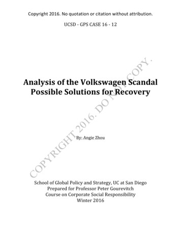
Cooling systemIntroductionTo maintain the engine free from aggressive media such as salt water, Volkswagen Marine boat engineshave a twin-circuit cooling system.Engine cooling circuitThe internal engine cooling circuit is a closed system and is mixed with antifreeze (G12/G12 ).The seawater /freshwater circuit, also called the secondary circuit, is an open circuit in which the seawater /freshwater is sucked in and, after flowing through the main heat exchanger, fed back to the outside againvia the exhaust system.Sea water / fresh water circuitSeawater / freshwater is sucked in through an intake cap in the boat’s hull, downstream of which there is aseawater / freshwater valve.The seawater / freshwater filter filters dirt and impurities from the entering seawater / freshwater.Aeration of the seawater / freshwater circuit using a ventilation unitTo prevent entry of seawater / freshwater into the exhaust system via the intake side of the seawater /freshwater circuit, a ventilation unit only has to be fitted if the engine is installed beneath the water line; (seefigure on page 6, item number 3.; Overview of the exhaust system installation).ExplanationIf the cooling system is beneath the water line, then filling of the exhaust system with water may occur, if theboat remains stationary for some time. This is because the seawater / freshwater pump is not 100 %watertight and causes a siphon / suction effect in the coolant circuit. If this occurs, close the seawater /freshwater valve.Connection for seawater/freshwaterConnect the seawater / freshwater hose -arrowedto the seawater / freshwater pump -1-.1EB6-0029Superior27 Technology
Cooling systemCooling circuit12 .4.5.6.7.8.9.10.11.12. Servo / gearbox oil cooler13. Sea water / fresh water cooling circuit14. Main heat exchanger15. Sea water / fresh water16. Sea water / fresh water filter17. Sea water / fresh water pump18. Intercooler19. Thermostat 70 C20. Engine-side coolant pump21. Right cylinder bank exhaust manifoldEngine ventilation positionOil coolerTemperature switch 112 CTemperature dual senderLeft cylinder bank exhaust manifoldCoolant expansion tankEngineExternal engine cooling circuitExternal heating supply connectionExternal heating return connectionVentilation positionSuperior28 Technology
Overview of seawater / freshwatercooling installation216345EB6-0019Legend1. Water line2. Engine3. Sea water / fresh water filter4. Sea water / fresh water valve5. Intake cap6. Seawater / freshwater connectionto the seawater / freshwater pumpSuperior29 Technology
Cooling systemIntake cap advice For motor boats, the sloping side of the intakemesh must point forwards. The fitting locationof the intake cap should be as far as possible inthe part of the boat shown hatched.In this case, the speed of the boat pushesthe water inwards.EB5-0017General Seawater / freshwater flows through theseawater / freshwater pump and then the mainheat exchanger after first flowing through theseawater / freshwater filter. The intake hose from the seawater / freshwaterfilter to the seawater / freshwater pump musthave a diameter of at least 45 mm. The hoseshould be as short as possible. In the main heat exchanger and the intercooler,the seawater / freshwater takes heat from thecoolant circuit and thus provides additionalengine cooling. Prior to over-wintering, the seawater / freshwater must be drained via the drainage screws-1- and -2-.21The measures required for overwintering the VOLKSWAGEN Marineboat engine are described in yourVOLKSWAGEN Marine boat engineinstruction manual.SuperiorEB6-003330 Technology
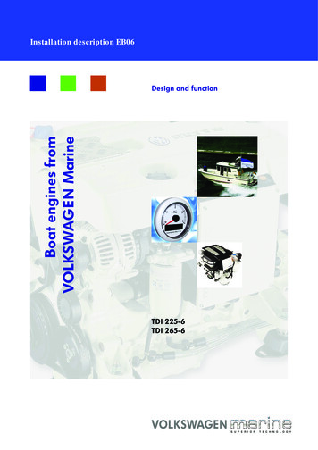
Fuel systemIntroductionThe fuel system comprises a number of components. These components (fuel tank, circulation prefilter withwater separator etc.) must be impeccably clean and should be fitted with extreme care.Dirt and impurities could cause incorrect engine operation. After installing the fuel system, check for leaks,to ensure optimum protection against fire risk.Functional description of the fuel systemEB6-0020Legend1.2.3.4.Fine fuel filter with water monitorManual pumpPressure maintenance valveHigh pressure accumulator (rail)5. Piezo injector6. High pressure pump with valve for fuel dosing(N290)7. Circulation prefilter with water separator8. Fuel tank9. Bleed screwPlease observe the instructionson the following page!Superior31 Technology
Fuel systemEngine fuel system overviewThe fuel system is divided into 3 pressure areas:1 - Supply and return pressure2 - Return pressure between injectors and pressure maintenance valve3 - High pressureIn the fuel supply, fuel is taken from the mechanical gear pump from the fuel tank via the fuel fine filter to thehigh pressure pump. Here the high fuel pressure required for injection is created and supplied to the highpressure accumulator (rail).From the high pressure accumulator, the fuel is transported to the injectors, from where it is injected into thecombustion chamber.The pressure maintenance valve maintains the return pressure of the injectors at 10 bar. This pressure isrequired for the correct functioning of the piezo-injectors.Requirements: The compartment containing the fuel system must be sufficiently ventilated. Fuel tankand filler cap must have an earth connection to the battery (for steel boats to the hull). When arranging the components, ensure that there is sufficient clearance for any futuremaintenance and repair work. A fuel return line is to be routed from the fuel tank to the fuel fine filter. The line cross sectionmust be at least 8 mm. A fuel return line is to be routed to the fuel tank. The line cross section must be at least8 mm.Superior32 Technology
Connection for the fuel supply lineConnect the fuel supply line to connection -2of the fuel fine filter -1-.21EB6-0023Bleeding the fuel line of the boatThe fuel line must be properly bled before theengine is put into operation.Open the bleed screw -9- (see figure EB6-0020on page 31) and work the hand pump until fuelcomes out of the bleed screw port.Then close the bleed screw.12Connection for the fuel return lineConnect the fuel return line to connection -1on the high pressure accumulator (rail)(cylinder bank 2) -2-.EB6-0027Superior33 Technology
Engine compartment ventilationIntroduction The engine must be supplied with air (oxygen), to ensure optimum fuel combustion. The engine must be sufficiently ventilated to ensure that the temperature can be maintainedat an optimum value, that is as low as possible.(ΔTmax. above ambient temperature: 10 C to 15 C). To ensure optimum engine compartment ventilation, the air inlet should be placed wherethe sucked-in air is as clean as possible and where the engine's own exhaust gases cannotbe sucked in. Water must not be able to enter either the air inlet or the air outlet. The hydraulic cross section for the air inlet must be at least 200 cm2. If other equipment that requires oxygen for its operation (e.g. an auxiliary heater) is locatedin the engine compartment, then this must also be considered when dimensioning the airinlet.Superior34 Technology
Engine components listFront view121211103498765EB6-0030Legend1.2.3.4.5.6.7. Main heat exchanger8. Engine oil drainage hose9. Oil extraction pump10. Alternator11. Central electrical system12. DipstickHydraulic oil reservoirCoolant expansion tankIntercoolerSacrificial anodeConnection for seawater/freshwaterSea water / fresh water pumpSuperior35 Technology
Engine components listView of starter side81723465EB6-0031Legend1. Button for oil extractor pump2. Housing for central electrical system andshifting bracket (Mercruiser shifting bracket)3. Connection for the fuel supply line4. Fine fuel filter with water monitorSuperior5.6.7.8.Oil sumpStarterAir filter elementTurbocharger36 Technology
View of gearbox sideEB6-0042Legend1.2.3.4.5.CoverExhaust pipe connectionTransmission bell housingHydraulic connectionServo / gearbox oil cooler6. Speed sender connection7. Gearbox neutral switch connection8. Optional accessory connection (e. g. boiler kit)9. Hydraulic pump10. Throttle lever position senderSuperior37 Technology
Technical DataEngine descriptionPermissible engine operating dataEngine codeTDI 225-6BSPPermissible engine temperatureEngine codeTDI 265-6CEZCubic capacity cm32967Maximum permissibletemperature in the oil sumpBore/strokemm C ( F) 135 (275)83/91.4Permissible coolant temperatureCompression ratio19.5:1Ignition sequence3-6-1-4-2-5Maximum permissibletemperature at the outletfrom the engine duringcontinuous operation C ( F) 105 (221)Power output(as per ISO 3046 with marine control unit)TDI 225-6at 4200 rpmkW165TDI 265-6at 4200 rpmkW195Charge air pressure(at rated power output and under standardizedoperating conditions)TDI 225-6at 4200 rpmbar1.25TDI 265-6at 4200 rpmbar1.50Engine electrical equipment12 V alternatorA180Starter 12 VkW2.0Battery 12 VA (Ah) 420 (88)minimum capacityWeightTDI 225-6kgapprox. 330TDI 265-6kgapprox. 330Diameters / Line cross sectionsExhaust systemØ 100 mmIntake hose forsea water / freshwaterØ 45 mm15 in all directionsFuel linesØ30 for short periodsBattery connection cableMaximum inclination during operation ) Superior38 Technology8 mm35 mm2
Cooling systemOil supplyTwin circuit cooling system (overpressure systemwith separate expansion tank and overpressurevalve) and seawater / freshwater circuit withimpeller pump.Engine oil qualityOil type VW Longlife, oil specificationVW 504 00/507 00 (5W30) (see also instructionmanual information)Overpressure valveOpens atbar (overpressure) 1.4 -1.6Oil pressureAt 2000 rpm and 80 C (176 F) engine oiltemperature (overpressure) at least 2.0ThermostatStarts opening at C ( F)70 (158)Oil consumption(maximum permitted) l/10 h0.05 - 0.1CoolantUse a mixture of 60% water and 40% G12/G12 antifreeze (colour lilac) as per TL VW 774D.Filling quantitiesCoolant circuitltr.approx. 9Including filter changeltr.6.0Volume differencebetween min. andmax. markingson the dipstickltr.approx. 1.3FuelFueldieselRequired minimumcetane numberas per DIN EN 590CN 51SuperiorOil circuit39 Technology
Installation dimensions for customizedCircular cut-out for round instruments in mm:Rev. counter Ø 85Voltmeter Ø 52Water temperature indicator Ø 52Ignition lock Ø 26Installation template for the control unit706313012365EB6-0037Superior40 Technology
Installation template for standard instrumentation 135121 95190176 EB5-0113Superior41 Technology
Superior42 Technology
Superior43 Technology
Installation description EB06 2007 VOLKSWAGEN MarineText, figures and standards in this guide are based on information current at the timeof printing. Reprinting, reproduction or translation, in whole or in part, is not permittedwithout the written approval of VOLKSWAGEN Marine. All rights according to theapplicable copyright laws are expressly reserved for VOLKSWAGEN Marine. Subject toalterations.Copy date 11/07Postfach 31 11 76, 38231 SalzgitterEdition 11/07 print number 066.991.EB06.20This paper was produced from wood pulp bleached without chlorine.
VOLKSWAGEN Marine boat engine, the suspension eyes provided on the engine (see figure) are to be used. Note: When removing the VOLKSWAGEN Marine boat engine from the transport container, make sure that the positioning device for the design cover (see -arrow-) is not damaged by the suspension chains or belts thus creating a risk of breakage.