Transcription
03.05.200510:47 UhrSeite 1Einbauanleitung EA02Installation Instruction EA02Einbauanleitung EA02Installation Instruction EA02Individual-InstrumentierungIndividual Instrumentation 2005 Volkswagen MarineDie Texte, Abbildungen und Normen in dieser Anleitung basieren auf dem Informationsstand zum Zeitpunkt der Drucklegung. Nachdruck, Vervielfältigung oder Übersetzung,auch auszugsweise, ist ohne schriftliche Genehmigung von Volkswagen Marine nichtgestattet. Alle Rechte nach dem Gesetz über das Urheberrecht bleiben VolkswagenMarine ausdrücklich vorbehalten. Änderungen vorbehalten.Redaktionsschluss 05/05The texts, illustrations and standards in this manual are based on the informationavailable at the time of print. Reprinting, reproduction or translation, in whole or in part,is not permitted without the written approval of Volkswagen Marine. All rights accordingto the applicable copyright laws are expressly reserved by Volkswagen Marine.Subject to change.Print status 05/05Postfach/POB 31 11 76, 38231 Salzgitter, GermanyAusgabe/Edition 05/05 Drucknummer/Publication Number 065.A91.A02.00/20 Dieses Papier wurde aus chlorfrei gebleichtem Zellstoff hergestellt.This paper was bleached without the use of chlorine.Bootsmotoren vonVolkswagen MarineEA02 0505 00 20.qxdTDI 100-5TDI 120-5TDI 150-5TDI 150-5DSDI 55-5SDI 75-5SDI 40-4SDI 50-4SDI 60-4
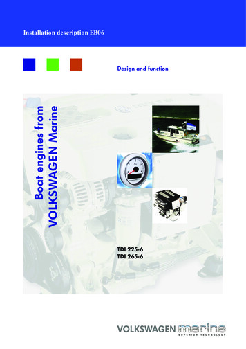
Individual InstrumentationVolkswagen Marine offers you the possibility to individually design your cockpit.You can select from the components described inthese installation instructions.Safety precautions: When installing this instrumentation, care must betaken that the electrical lines are carefully and properly laid. Cable plugs must be plugged in securely and engaged to ensure correct functioning. Additional voltage drops for other instruments ordevices may only be connected to the terminal strip(X14) of the operating unit (max. 2 ampere each forKl.15 -ignition on- and Kl.30 -permanent live-). The contact on the terminal strip X14-3 -dimmerlighting- should be used for lighting these instruments or devices.General Information:A comprehensive description of the individual functions for the revolution counter’s multifunction displaycan be found in the operation manual and supplemental operation manual in your on-board booklet.1Overview of the scope ofsupply1 - Rev. counter with multi-function display Description page 22 Display range0.4000 RPM122 - Operating unit with connection for diagnosticsystem tester33 - Indicator lamp Qty 3 for voltmeter, water temperature indicator and oil pressureindicator to be built in to the back of therespective instrument beforeassembly87654EA2--00212
4 - Wiring harness complete Description page 95 - Ignition switch with 2 ignition keys Description page 21126 - Water temperature indicator Description page 19 Display range40 .120 37 - Oil pressure indicator Description page 20 Display range0.5 bar88 - Voltmeter Description page 18 Display range8.16 Volt7654EA2--00213Listing of instrument set 065 800 547 B:Quan- Part NumbertityManufacturerPart NumberVolkswagenMarineDesignation1-065 959 714Operating unit1N 02 012 911065 920 800Rev. counter1N 02 124 106065 857 002Oil pressure indicator1N 02 321 602065 857 003Water temperatureindicator1N 02 410 802065 857 001Voltmeter132 83 50065 905 845Ignition switch1-065 951 307Buzzer1-065 971 086Line for voltmeter1-065 971 086 ALine for oil pressureindicator1-065 971 086 BLine for watertemperature indicator1-065 971 086 CLine for rev. counter1-065 971 086 DLine for ignition switch3N 05 800 7622Y1 919 240Indicator lamp4
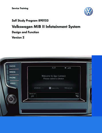
Operating unit (front side)124351 - Operating unit Installation template page 252 - Control lamp for glow plugsystem and engine fault3 - Button for dimmer regulationof the instrument lighting4 - Acknowledgebuttonacoustic signalfor5 - Button for multifunction display You will find information onthis in the operation manualand supplemental operationmanual in your on-board booklet.66 - Cover for diagnostic connection Connection page 24EA2--00125Operating unit (rear side)12345 61 - Operating unit Installation template page 251471382 - Connection plug T22 white from the operating unit to thecentral electrical system Contact assignment page 103 - Connection plug T22a from the operating unit to theflying bridge Contact assignment page 124 - Connection plug T3 from the operating unit to theignition switch Contact assignment page 141211105 - Fuse (2 ampere) F2 terminal 30 (Permanentlive)9EA2--00056
Continued12346 - Fuse (2 ampere) F1 terminal 15 (ignition on)5 67 - Relay for instrument lighting1471388 - Connection plug T5 from the operating unit to theoil pressure indicator Contact assignment page 169 - Connection plug T6 from the operating unit to thewater temperature indicator Contact assignment page 1610 - Buzzer12111011 - Connection plug T12 from the operating unit to therev. counter Contact assignment page 159EA2--00057123412 - Connection plug T4 from the operating unit to thevoltmeter Contact assignment page 145 613 - Connection strip X14 Operating unit terminal strip Contact assignment page 1714714 - Gasket Renew if damaged1381211109EA2--00058
Description of the wiringharness21 - Connecting wires for rev. counter2 - Connecting wires for voltmeter Connection contact assignment and - pay attention at thevoltmeter13 - Connecting wires for ignitionswitch34 - Connecting wires for oil pressure indicator Connection contact assignment and - pay attention at the oilpressure indicator55 - Connecting wires for watertemperature indicator Connection contact assignment and - pay attention at the water temperature indicator4EA2--00229Contact assignment of the individualconnection plugs:11Connection plug T22 (white), operating unit tofuse box/relay ive speed signalT22-2D for cutoff relayT22-3Neutral from the gearboxT22-4Terminal 31 (earth)T22-5System lampT22-6Terminal 50a (start)T22-7Ignition on at fuse box/relayplateT22-8Stop at fuse box/relay plateT22-9Terminal 30 (permanent live)10
ater temperature switchT22-11Water temperature senderT22-12Neutral at fuse box/relay plateT22-13Oil pressure switchT22-14Sensor for water in fuelT22-15Alarm relay acknowledgementT22-16Sensor for water levelT22-17CAN-LowT22-18BuzzerT22-19Charge monitoringT22-20K lineT22-21Oil pressure senderT22-22CAN-High1122Connection plug T22a (black)Operating unit to the flying al speed signalT22a-2Instrument lighting earthT22a-3Neutral from the main panelT22a-4Terminal 31 (earth)T22a-5System lampT22a-6Terminal 50a (start)T22a-7Terminal 15 (ignition on) fromthe main panelT22a-8Stop at fuse box/relay plate(over the main panel)T22a-9Terminal 30 (permanent live)T22a-10Water temperature switchT22a-11NMEA-A (navigation system)T22a-12NeutralT22a-13Oil pressure switchT22a-14Sensor for water in fuel12
Alarm relay acknowledgementT22a-16Sensor for water levelT22a-17CAN-LowT22a-18BuzzerT22a-19Charge monitoringT22a-20Dimmer buttonT22a-21NMEA-B (navigation system)T22a-22CAN-High131Connection plug T3 (white)Operating unit to the ignition switch3ContactDesignationT3-1Terminal 30 (permanent live)T3-2Terminal 15 (ignition on)T3-3Terminal 50aEA2--00181 2Connection plug T4 (black)Operating unit to the voltmeter3 4EA2--0017ContactDesignationT4-1Terminal 15 (ignition on)T4-2Terminal 31 (earth)T4-3Instrument lightingT4-4D 14
6Connection plug T12 (black)Operating unit to the rev. T12-2Instrument lightingT12-3NMEA-A (navigation system)T12-4CAN-HighT12-5CAN-LowT12-6NMEA-B (navigation system)T12-7Sensor for water levelT12-8Water separatorT12-9Terminal 31 (earth)T12-10ButtonsT12-11Terminal 15 (ignition on)T12-12Terminal 30 (permanent live)15Connection plug T5 (black)operating unit to the oil pressure nal 15 (ignition on)T5-2Terminal 31 (earth)T5-3Instrument lightingT5-4Oil pressure switchT5-5Oil pressure senderConnection plug T6 (black)Operating unit to the water temperature indicator6EA2--0008ContactDesignationT6-1Terminal 15 (ignition on)T6-2Terminal 31 (earth)T6-3Instrument lightingT6-4Water temperature switchT6-5Water temperature senderT6-6Vacant16
71814EA2--0006Terminal strip X14 (grey)Operating unitContactDesignationX14-1NMEA-A (navigation system)X14-2NMEA-B (navigation system)X14-3Instrument lightingX14-4External speed signalX14-5Terminal 31 (earth)X14-6Terminal 31 (earth)X14-7D cutoff relayX14-8Terminal 15 (ignition on)X14-9Terminal 30 (permanent live)X14-10Neutral from the gearboxX14-11Neutral at fuse box/relay plateX14-12Neutral at flying bridgeX14-13K lineX14-14Vacant17Description of the instruments andcomponents:VoltmeterA1Located on the rear side -A- of the voltmeter are theelectrical connections, with the following contact assignment:2ContactDesignation31Instrument lighting2Warning lamp3Terminal 154Terminal 31 (earth)4EA2--0002Note:When connecting, pay attention to the correct designation of the contact assignment ( and -).18
Water temperature indicatorA15Located on the rear side -A- of the water temperatureindicator are the electrical connections, with the following contact assignment:2ContactDesignation341Instrument lighting2Warning lamp3Water temperature sender4Terminal 155Terminal 31 (earth)EA2--0014Note:When connecting, pay attention to the correct designation of the contact assignment ( and -).19Oil pressure indicatorA51Located on the rear side -A- of the oil pressure indicator are the electrical connections, with the followingcontact assignment:2ContactDesignation31Instrument lighting2Warning lamp3Oil pressure sender4Terminal 155Terminal 31 (earth)4EA2--0003Note:When connecting, pay attention to the correct designation of the contact assignment ( and -).20
Ignition switchA1Located on the rear side -A- of the ignition switch arethe electrical connections, with the following rminal 30 (permanent live)2Terminal 153Terminal 50a21Rev. counterLocated on the rear side -A- of the rev. counter arethe electrical connections, with the following contact T14-2/BWater separatorT14-3/CNeutralT14-4/DNMEA-A (navigation system)T14-5/ENMEA-B (navigation system)EA2--001322
2/B1/AEA2--0013ContactDesignationT14-6/FTerminal 31 (earth)T14-7/GTerminal 30 (permanent 4-11/LProbeT14-12/MSensor for water levelT14-13/NInstrument lightingT14-14/PTerminal 15 (ignition on)23Connection for system tester (self-diagnosis)- Unscrew the 2 fastening screws of the cover on theoperating unit -1-.- Connect the diagnosis plug -2- from the system tester to the operating unit connection.12EA2--002024
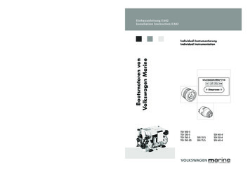
Installation template for operating unit7063130123656525
03.05.200510:47 UhrSeite 1Einbauanleitung EA02Installation Instruction EA02Einbauanleitung EA02Installation Instruction EA02Individual-InstrumentierungIndividual Instrumentation 2005 Volkswagen MarineDie Texte, Abbildungen und Normen in dieser Anleitung basieren auf dem Informationsstand zum Zeitpunkt der Drucklegung. Nachdruck, Vervielfältigung oder Übersetzung,auch auszugsweise, ist ohne schriftliche Genehmigung von Volkswagen Marine nichtgestattet. Alle Rechte nach dem Gesetz über das Urheberrecht bleiben VolkswagenMarine ausdrücklich vorbehalten. Änderungen vorbehalten.Redaktionsschluss 05/05The texts, illustrations and standards in this manual are based on the informationavailable at the time of print. Reprinting, reproduction or translation, in whole or in part,is not permitted without the written approval of Volkswagen Marine. All rights accordingto the applicable copyright laws are expressly reserved by Volkswagen Marine.Subject to change.Print status 05/05Postfach/POB 31 11 76, 38231 Salzgitter, GermanyAusgabe/Edition 05/05 Drucknummer/Publication Number 065.A91.A02.00/20 Dieses Papier wurde aus chlorfrei gebleichtem Zellstoff hergestellt.This paper was bleached without the use of chlorine.Bootsmotoren vonVolkswagen MarineEA02 0505 00 20.qxdTDI 100-5TDI 120-5TDI 150-5TDI 150-5DSDI 55-5SDI 75-5SDI 40-4SDI 50-4SDI 60-4
auch auszugsweise, ist ohne schriftliche Genehmigung von Volkswagen Marine nicht gestattet. Alle Rechte nach dem Gesetz über das Urheberrecht bleiben Volkswagen Marine ausdrücklich vorbehalten. Änderungen vorbehalten. Redaktionsschluss 05/05 The texts, illustrations and standards in this manual are based on the information