Transcription
More info about this article: http://www.ndt.net/?id 21189TITLE: Risk BasedAssessment of above Ground Storage Tank bottoms – Role of MagneticFlux Leakage Technique*Santanu Saha. Intertek-Inspec; UAEPO Box: 6130. Sharjah.Email: Santanu.saha@intertek.comABSTRACT:Corrosion of aboveground storage tank bottom plates is a common damage mechanism found inseveral Petroleum storage tanks in the Middle Eastcountries and in the world at large. Corrosionof the floor plates can occur either from the underside (soil side) or from the top side (productside). Both types of corrosion is common in the storage tanks and eventually lead to metal lossand ultimately perforations in the tank floor. The consequence of such failures are sometimessevere with respect to loss of containment, possibility of explosion and loss of human lives anddamage to the environment. The accumulation of water at the bottom of storage tanks is aprimary prerequisite for development of corrosion. On the other hand, soil side corrosion fromunderside the floor plate sometimes plays a predominant role in the premature loss of productand failure of the tank in service. Although the product side of the floor plates are generallyprotected with various types of non-corrosive paint coatings and there are several protectivemeasures including cathodic protection and use of dry compacted sands with chemical inhibitorswere existent to protect the soil side of the floor plates, several failures of bottom plates in termsof through holes and/ or severe corrosion of the bottom plates almost reaching down to theminimum allowable thickness have been noticed in quite a few cases. It has been noticed that inmany cases the soil side (underside) corrosion occurred mostly at or near the annular platesparticularly in the critical zones inside the tank. Magnetic Flux Leakage Technique is a veryuseful tool to assess the corrosion of bottom plates of Storage tanks and hence is a preliminaryrequisite for Risk assessment of Storage tanks in service. In this present case study, an abovestorage tanks which was taken out of service for scheduled maintenance and inspection, has beensubjected to thorough magnetic flux leakage examination of entire bottom plates. During theMFL examination, several areas of significant corrosion have been observed in the bottom platesand an assessment of fitness for service have been carried out based on Risk Based Inspection inaccordance with the guide lines of API RP 580 & 581. A general recommendation have beenprovided based on RBI study and API 653 recommendations.Keywords: Soil corrosion, paint blisters, storage tank bottom, fitness for service, risk basedinspection, Magnetic Flux Leakage.267Non-Destructive Evaluation 2016
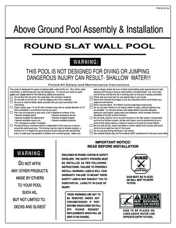
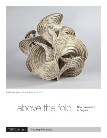
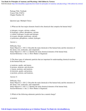
1. Introduction:An oil storage tank has been internally and externally inspected in accordance with theguidelines of API 653: 2014 edition. The tank was built in the year of 1970 and has beenin service since then with some local minor repairs. The details of the tank is givenbelow:1.1 Diameter: 34.14 meter1.2 Height: 14.5 meter1.3 Product stored: Gas Oil.1.4 Year of construction: 19701.5 Product specific gravity: 0.841.6 Internal pressure: Atmospheric1.7 Bottom/ annular plate thickness: 7.5mm / 10mm.1.8 Roof plate thickness: 6mm.1.9 Shell plate thickness: 10mm to 6mm (bottom to top shell course)1.10 No of shell courses: 8 nos.1.11 Material of construction: Not known (assumed to be ASTM A 36).During internal inspection of the storage tank, several through holes were observed in the bottomplates and annular plate associated with several corroded areas of bottom plates. Roof plateswere also severely corroded and through holes were observed in several areas of roof plates. In atleast one area of the shell plates, a through hole was observed. A large portion of the shell in the3rd to 4th shell portion was found deformed towards inside. Other than that, general and localizedcorrosion were observed in attachment welds, hand rails, staircases and nozzle welds. A report ofmagnetic flux leakage survey has also been shown in photo-3, which reveals several areas ofbottom plate corrosion. Suitability for service assessment has been done as per API 653 and itwas observed that at the present condition, the tank cannot be operated under the existingoperating conditions. Repairs of the affected areas have been recommended. The owner hasdecided to replace the roof completely and full replacement of the affected location of the shellplate by putting one new insert plate. However the bottom plate replacement is a cumbersometask and will take huge time to replace, hence they asked us to have a general RBI study of thebottom plates whether with the existing condition and after all repairs have been carried out thetank bottom, the tank can run for another 5 years. A team comprising API RBI engineer and API653 inspector has performed RBI study and following are the conclusion and still it wasobserved that the risk of operating the tank is quite high and replacement of bottom plate isnecessary to run it for another 5 years. Here is a brief summary of the work that has been carriedout to estimate the risk of the tank serviceability as per API 580 & 581.2. Risk analysis procedure:2.1 In API RBI, the risk as a function of time is calculated in accordance with the followingformula. The equation combines both probability of failure and consequence of failure and is aproduct of both factors. Only financial risk is used for atmospheric storage tank components.R(t) P f (t) xFC (1)268Non-Destructive Evaluation 2016
Probability of failure is a function of time since the most damage factors are time variant andthus the severity increases as the time increases. The thinning damage factor for storage tanks ismainly a time dependent phenomenon. On the other hand, the consequence of failure is generallyconsidered as time invariant and hence time does not have much effect on the consequence offailure. For storage tanks the consequence is mainly financial based.2.2 Risk Matrix:The results combined and summarized in a risk matrix is an effective way of showing thedistribution of risks for different components in a process unit without numerical values. In therisk matrix, the consequence and probability categories are arranged such that the highest riskcomponents are toward the upper right-hand corner. The risk matrix may be expressed in termsof consequence area or financial consequence. In the case of storage tanks, the consequence ismainly financial based.Risk categories (i.e. High, Medium High, Medium, and Low) are assigned to the boxes on therisk matrix. In API RBI the risk categories are asymmetrical to indicate that the consequencecategory is given higher weighting than the probability category.Tank components residing towards the upper right-hand corner of the risk matrix will most likelytake priority for inspection planning because these items have the highest risk. Similarly, itemsresiding toward the lower left hand corner of the risk matrix tend to take lower priority becausethese items have the lowest risk. Once the plots have been completed, the risk matrix can then beused as a screening tool during the prioritization process.2.3 Probability of Failure:The probability of failure as a function of time and inspection effectiveness is determined using ageneric failure frequency and damage factors for the applicable active damage mechanisms.Forthe storage tank in question, we utilized the thinning damage factor which is typically used fortank components. However, damage factors for other active damage mechanisms may also becomputed.2.4 Consequence of Failure:Consequence of failure calculation procedures to be used is provided in API RP 581 in a verydetailed way. Only the Level 1 consequence analysis in financial terms is used for the analysis oftank components. In addition, only consequences from component damage, product loss, andenvironmental penalties are considered.2.5 Inspection Planning Based on Risk AnalysisIt is understood that at some point in time, the estimated risk will reach a specified risk target.Therefore, inspection of the equipment is recommended based on a ranking of the componentdamage mechanisms that have the highest calculated damage factors. Inspection provideknowledge of the damage state of the Tank and reduces uncertainty. The probability that loss ofcontainment will occur is directly related to the amount of information that is available frominspection and the ability to quantify that damage.Reduction in uncertainty is a function of the effectiveness of the inspection in identifying andquantifying the type and extent of the damage. Some inspection techniques are better, forexample, in detecting thinning (general corrosion) damage than others. On the other hand, aninspection technique appropriate for general corrosion may not be very effective in detecting andquantifying damage due to local thinning or cracking.269Non-Destructive Evaluation 2016
3.0 Probability of Failure calculation:API RP 581 suggests the probability of failure shall be calculated by the following formula:P f (t) gff x Df (t) x F ms . (2)In this equation, the probability of failure, Pf (t), is determined as the product of a generic failurefrequency, gff, a damage factor, Df (t), and a management systems factor, F ms.The adjustment factors on the generic frequency of failure reflect differences between damagemechanisms andthe reliability management processes within a plant. The damage factor adjuststhe generic failure frequencybased on the active damage mechanisms the component is subject toand considers the susceptibility to thedamage mechanism and/or the rate at which the damageaccumulates. The damage factor also takes intoconsideration historical inspection data and theeffectiveness of both past and future inspections.3.1 Management System Factor:Themanagement systems factor, adjusts for the influence ofthe facility‘s management system on the mechanicalintegrity of the plant. The damage factor isapplied on a component and damage mechanism specific basiswhile the management systemsfactor is applied equally to all components within a plant.Adjustment factors with a value greater than 1.0 will increase the probability of failure, and thosewith a valueless than 1.0 will decrease it. Both adjustment factors are always positive numbers.The generic failure frequency of a component type is estimated using records from all plantswithin a company or from various plants within an industry, from literature sources, andcommercial reliability data bases. Therefore, these generic values typically represent an industryin general and do not reflect the true failure frequencies for a specific component subject to aspecific damage mechanism.3.2 Generic Failure frequency:The generic failure frequency is intended to be the failurefrequency representative of failures due to degradation from relatively benign service prior toaccounting for any specific operating environment, and are provided for several discrete holesizes for various types of processing equipment (i.e. process vessels, drums, towers, pipingsystems, tankage, etc.).The overall generic failure frequency for each component type was divided across the relevanthole sizes, i.e. the sum of the generic failure frequency for each hole size is equal to the totalgeneric failure frequency for the component.3.3 Damage Factors:Damage factors are intended to support the API RBI methodology byproviding a screening tool to determine inspection priorities and to optimize inspection efforts.Damage factors do not provide a definitive Fitness-for-Service assessment of the component.The basic function of the damage factor is to statistically evaluate the amount of damage thatmay be present as a function of time in service and the effectiveness of an inspection activity.4.0 Calculation of Probability of failure:As described in the previous paragraph, the probability of failure is a product of generic failurefrequency (gff), the damage factor (Df (t)) and the management system factor (F ms).For the purpose of the probability calculation of tank bottom plates, the thinning has beenconsidered in this study.Thinning damage factor Dfthin4.1 Calculations:Since the tank has no release prevention barrier, the minimum required thickness as per API 653is 2.54mm for bottom plates.270Non-Destructive Evaluation 2016
The Art parameter (Damage factor parameter):Art can be calculated as below:Art Maximum of [{1- (trd – Cr,bm x age)/(tmin CA)}; 0.0]For the present tank:Trd Thickness of the bottom plates at the time last inspection. Since the tank was running forquite a long time without any effective inspection and no data is available, the thickness wastaken as the measured thickness during installation, which is 7.5mm.Cr,bm Corrosion rate (long term) is calculated based on the simple principle described in API653, which is calculated as maximum 0.089mm / year.Age the age of the tank is 46 years since its installation.Tmin The minimum allowable thickness as per API 653 2.54mm for bottom plates.CA corrosion allowance 0.00mm.Based on the above information, the Art parameter can be calculated as:Art Maximum of [{1- (trd – Cr,bm x age)/(tmin ωA)}; 0.0] .(γ) maximum of [{1-(7.5 – (0.0891 x 46)/2.54)}; 0.0] 0.34API 581 provides a table for the calculation of thinning damage factor to be used for probabilityof failure calculations (Table 5.12) specifically for storage tank bottoms.From the table 5.12, the thinning damage factor for tank bottom with no effective inspection &Art value of 0.34;The thinning damage factor can be taken as: DfBthin 170So the composite damage factor for thinning damage mechanism taking into account all theadjustment parameters will be:The damage factor for thinning; Dfthin (DfBthin x FIP x FDL x FWD x FAM x FSM) / FOM .(4)Where:FOM Adjustment factor for online monitoring 1 for tank bottom corrosion.F
out to estimate the risk of the tank serviceability as per API 580 & 581. 2. Risk analysis procedure: 2.1 In API RBI, the risk as a function of time is calculated in accordance with the following formula. The equation combines both probability of failure and consequence of failure and is a product of both factors. Only financial risk is used for atmospheric storage tank components. R(t) Pf .