Transcription
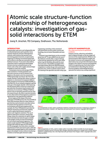
environmental transmission electron microscopyAtomic scale structure-functionrelationship of heterogeneouscatalysts: investigation of gassolid interactions by ETEMJoerg R. Jinschek, FEI Company, Eindhoven, The NetherlandsINTRODUCTIONCatalysts play a pervasive and indispensible rolein industrial processes used to produce manyessential chemicals and fuels. Heterogeneouscatalysts, solid catalysts that promote reactions among gaseous reactants, are particularlyimportant in refining conventional fossil fuelsand in efforts to develop new renewable fuel andfeedstock resources. To succeed in these efforts,researchers need to understand relationshipsbetween structure and performance at theatomic scale as they seek to apply rational designstrategies to create new catalysts.Transmission electron microscopes (TEMs)allow scientists to visualize geometric andelectronic structure as well as chemical composition at the atomic scale, but conventionalTEMs require high vacuum (at 10-5 Pa) in thesample chamber, limiting their ability to observecatalysts in a functional environment. Differentially pumped environmental TEMs (ETEMs), asdescribed in [1, 2], are uniquely designed to permitsome gas in the sample chamber while balancingthe detrimental effects of electron scattering bygas molecules, thus preserving the atomic scaleresolution of conventional TEM [3]. ETEM hasproven to be an extremely powerful tool for catalysis research (e.g. [4, 5]), where it permits dynamic,in-situ observations of heterogeneous catalysts inoperational (or near operational) conditions.Several aspects of the design of the latestgeneration of ETEMs (such as the Titan ETEM G2from FEI) contribute directly to their ability toprovide time resolved atomic scale observationsof catalysts during exposure to reactive gasenvironments and elevated temperatures. Forexample, the Titan TEM platform provides theinherent mechanical and electronic stabilityas well as optical performance required toachieve sub-Ångström resolution. The use ofspherical aberration correctors, among otherthings, relaxes the constraints on optical designthat would otherwise limit the space availablein the sample vicinity for the environmentalcell and related experimental apparatus. Thesystem accepts standard TEM sample holdersand provides sufficient space for full doubletilt 3D tomography. Gas inlets allow controlledintroduction of inert and reactive gases, while thedifferentially pumped objective lens confines thegases to the sample vicinity without introducingwindows in the beam path. Extensive safetyengineering, including a fully automatedand interlocked vacuum system, ensures safehandling, even of certain flammable and toxicgases.Pressures in gas experiments can be accuratelypreset from 10-3 Pa up to 2000 Pa (in the case ofN2). Software controls offer a range of settingsto provide easy operation by novice users whilepreserving the flexibility demanded by moreadvanced users. The ETEM is equipped with amass spectrometer (RGA) for determining gascomposition in either the gas inlet system or thespecimen area. A built-in plasma cleaner allowsfor cleaning of the specimen area after using a gas.CATALYST NANOPARTICLESSize, shape and structure in operationalconditionsCatalytic activity, selectivity and stabilityseem to depend strongly on the size, shape andstructure of the catalyst particles. While ex-situcharacterization offers important insight intothe catalyst’s structure and composition, theseobservations may not provide information aboutchanges in the catalyst’s structure and propertieswhile in its operating state. Such observationsare fundamental to describing the catalyst’sstructure-property relationships because inoperando the catalyst may undergo significantFigure 1Cu nanoparticles on ZnO, used to synthesize methanol, change their structure in response to changes inthe gas environment. (Details in [4]. Reprinted with permission from Science. Copyright 1997 AAAS.)Figure 2Gold nanoparticles on CeO2, used to oxidize carbon monoxide, exhibit reversible structural changes,reverting to faceted ‘vacuum’ structure after changes induced by exposure to oxygen and a CO/air mixture.(Details in supplementary info in [8]. Reprinted with permission from Angew. Chem. Copyright 2011 JohnWiley and Sons.)MicroscopyandAnalysis Nanotechnology Issue November 20125
environmental transmission electron microscopyFigure 3Co/CoOX catalysts, used in the Fischer-Tropschsynthesis to convert syngas (a mixture of hydrogenand carbon monoxide) into liquid fuels, exhibitchanges in morphology in response to elevatedtemperatures and exposure to hydrogen. Reductionof CoOX to metallic cobalt results in an increasein effective particle size. (Details in [15]. Reprintedwith permission from ACS Nano. Copyright 2012American Chemical Society.)changes to become active. It is thereforeessential to obtain structural information aboutcatalysts under reactive conditions, such asat elevated temperatures and gas pressures, inorder to understand and improve the activity,functionality, and stability of new catalysts (seeexamples in Figures 1 -3).AUTOMOTIVE CATALYTICCONVERTERS FOR POLLUTIONCONTROLCeria zirconiaNanoscale ceria zirconia particles are a criticalcomponent in automotive catalytic converters,and have potential applications in other areas,such as fuel cells, where redox functionalityis important. In situ studies by Wang et al. [6]have followed the dynamic redox process takingplace in individual ceria zirconia nanoparticles.Observations have correlated catalytic activitywith changes in the particle’s oxidation state(Figure 4). The more active particle structure haspredominantly disordered cations and showsno evidence of oxygen vacancy ordering duringreduction.CATALYST ACTIVATIONProduction of Syngas by partial oxidation ofmethane over Ni/SiO2Partial oxidation of methane (POM) is animportant reaction for the production of syngas, afeedstock for the production of a variety of liquidhydrocarbons. POM may also be useful for otherenergy related processes, such as reforming fuelfor high temperature fuel cell applications.Supported nickel (Ni) catalysts are lessexpensive than noble metal and have shown highconversion rates. Chenna et al. [7] have reportedthat during ramp up Ni catalysts proceed throughan activation sequence in which they firsttransform to NiO shells at temperatures above300 C, then back to Ni as further increases intemperature make the gas environment morereducing. Syngas formation only takes placeduring the later stages of NiO reduction, whenNi metal nanoparticles have broken through theNiO shell. When initially observed, the void-likestructures were somewhat surprising as they hadnot been seen previously in used catalysts (seeFigure 5).Figure 4 (above)In-situ high resolution TEM (HRTEM) images (leftand right) of nominally identical ceria zirconiananoparticles recorded at 586 C in 1.5 Torr of H2.The inserted electron energy loss spectra (EELS)indicate the electronic structure of the particleunder observation. The derived graph in the centerplots the oxidation state for the same two particlesas a function of temperature to be able to identifythe catalytically active nanoparticle. (Details in[6]. Reprinted with permission from NanoLetters.Copyright 2008 American Chemical Society.)Figure 5Above: Conversion andselectivity for partialoxidation of methane(POM) over a model 2.5wt% Ni/SiO2 catalyst.Left: The in-situ TEMimages show thedevelopment of voidedstructures at 400 C asthe gas environment ischanged from 1 mbarH2 (top) to 1 mbar 2:1mixture of CH4 and O2(middle). The lowerimage diagrams NiOvoid formation bythe Kirkendall effect.(Details in [7]. Reprintedwith permission fromChemCatChem.Copyright 2011 JohnWiley and Sons.)Temperature-dependentcatalyst activityCO oxidation over Pt/CeO2Low temperature carbon monoxide (CO)oxidation is needed in various applications, suchas indoor air purification, safety devices (e.g. inlaboratories using CO), submarine ventilationsystems, and catalytic converters for cold-start6Nanotechnology Issue November 2012 MicroscopyandAnalysis
environmental transmission electron microscopyemissions control in automotive exhaust.Another important application is the purification of hydrogen for use in fuel cells or as afeedstock for energy and chemical producingprocesses. The hydrogen rich gas mixture produced by steam reformation of hydrocarbon fueltypically contains 1% CO. This relatively smallamount of CO is still enough to poison active siteson a catalyst, such as the electrodes of a fuel cell.Selective catalytic oxidation is the most effectiveway to remove low levels of CO from hydrogen.An efficient CO oxidation catalyst must be highlyselective, to avoid oxidizing the hydrogen, and resistant to CO2 and H2O deactivation. Noble metalcatalysts on transition metal oxides have showninteresting performance in this application.CO conversion over platinum (Pt) nanoparticlessupported on ceria (CeO2) increases rapidly ataround 40 C (Figure 6). As the temperatureincreases from room temperature in CO/air,the round Pt particles become partially faceted.Yoshida et al. [5] compared the shape of Ptparticles under various conditions. Thereby itis possible to understand the mechanism for theshape change and the temperature dependence ofFigure 6Left: CO oxidation over Pt/CeO2 catalysts is afunction of temperature.Top: In-situ TEM images and corresponding Wulffconstructions show changes in particle structureobserved with changes in gas environment andtemperature. Pt/CeO2 particles exhibit low activityin vacuum at room temperature (top) and in CO/airat room temperature (middle). Conversion activityincreases dramatically at elevated temperature(bottom). (Details in [5]. Reprinted with permissionfrom Applied Physics Express. Copyright 2011Japan Society of Applied Physics.)Figure 7The morphology of Aunanoparticles supported onCeO2 changes as a function ofthe partial pressures of CO andO2 in CO/air mixtures. (Detailsin [8] Reprinted with permissionfrom Angew. Chem. Copyright2011 John Wiley and Sons.)Figure 8Left: Under catalytic conditions the gold nanoparticles exhibit Au{100}-hex reconstructed surface structures. In the reaction environment the distance betweenthe topmost and second topmost {100} surface layers increases (from 0.20 nm to 0.25 nm) and distance between adjoining atomic columns in the topmostsurface layer decreases (from 0.29 nm to 0.25 nm).Right: A gold nanoparticle supported on CeO2 observed in reaction conditions displays a persistent and unusual feature at the upper right edge of the particle(left3 images). The two illustrations at upper right show a model of the particle with adsorbed CO molecules. Images at lower right show good agreement between acalculated image based on the model and the experimentally observed image, confirming the presence of the Au{100}-hex reconstructed surface with adsorbedCO molecules. (Details in [9]. Reprinted with permission from Science. Copyright 2012 AAAS.)MicroscopyandAnalysis Nanotechnology Issue November 20127
environmental transmission electron microscopythe CO conversion rate (Figure 6). The change inshape of the Pt particles may be induced by theadsorption of CO molecules and O atoms.SURFACE STRUCTURE AND GASCOMPOSITION:Room temperature CO oxidation over Au/CeO2Bulk gold (Au), a noble metal, is stubbornlyunreactive, but Au nanoparticles are quitedifferent (Figure 7). Au nanoparticles supportedon crystalline metal oxides, such as CeO2, arevery active towards the conversion of CO toCO2, even at or below room temperatures [8].The conversion has two steps: the cleaving of theO-O bond and the transfer of an O atom to a COmolecule. Direct visualization of surface facets,surface reconstructions, atoms and adsorbed gasmolecules is vital to understanding the catalyticmechanism (Figure 8) [9].Reduction-Oxidation cycleReliability studies of SOFC fuel cellA fuel cell is an energy conversion device thatconverts chemical energy into electrical energythrough an electrochemical reaction (Figure 9).The most commonly used fuel is hydrogen (H2)gas, but hydrocarbons, such as natural gas andalcohols can also be used. Solid oxide fuel cells(SOFC) are a class of fuel cell characterized by theuse of a solid oxide material as the electrolyte.Advantages of SOFCs include flexibility of thefuel used (e.g. CO, H2, CH4), delocalization ofenergy production, and reduction of pollutantssuch as mono-nitrogen oxides (NOX) and sulfuroxides (SOX). SOFCs also offer high efficiency,long term stability, low emissions and relativelylow cost.A standard SOFC design uses an anode ofporous ceramic-metal composite yttria (Y2O3)stabilized zirconia (YSZ) and nickel (Ni). In-situinvestigation, such as by Jeangros et al. [10], canhelp in understanding decreasing performanceof fuel cells caused by structural changes in theanode during operation cycles (Figure 9).Diesel automotive exhaustclean-upSoot oxidation over CeO2Carbonaceous nanoclusters, such as soot particlesin the exhaust of diesel engines, have a negativeimpact on our climate and constitute a healthrisk. Increased awareness of these effects hasresulted in new environmental regulations thatimpose stricter limits on exhaust emissions.Soot particle emissions may be reduced eitherby optimizing the combustion inside the engineor by removing the carbonaceous particles fromthe gaseous exhaust stream. The particles may beremoved with a filter but the filter will eventuallyfill up and need replacement or regeneration.One approach to onboard regeneration involvesfunctionalizing the filter for catalytic oxidationof the deposited soot.CeO2-based materials are widely used forthis purpose. In situ TEM observations of theoxidation of soot particles on CeO2 by Simonsenet al. [11] show the particles growing shorter butnot decreasing in diameter, which suggests thatthe oxidation occurs near the CeO2 surface (Figure10).8Figure 9Left: Reduction oxidation cycle in a SOFC fuel cell. Right: The upper in situ TEM images show in situreduction of NiO-YSZ anode precursor in 1.4 mbar of H2. Nanoporosity is observed forming in the NiOgrains as they accommodate the volume shrinkage that results from the reduction of NiO to Ni. Lowerimages show reoxidation in 3.2 mbar O2. With increasing temperature, the nanoporosity that was createdduring in situ reduction is filled by polycrystalline NiO. This occupies a larger volume than that of the assintered grains. Stress is observed in the YSZ phase, accumulating over successive redox cycles. (Details in[10]. Reproduced with permission from Acta Materialia. Copyright 2010 Elsevier.)Nanotechnology Issue November 2012 MicroscopyandAnalysis
environmental transmission electron microscopyFigure 10Top: In situ TEM image sequence of soot particlesattached to CeO2 are oxidized by exposure to 2mbar of O2 at 475 C. The reduction in the length ofthe particles while the diameter remains constantsuggests that the oxidation is occurring near theCeO2 surface.Below: Oxidation of soot particles on CeO2. Theleft figure plots particle diameter (open points)and distance to CeO2 (closed points) over time.The middle figure plots the mean change indistance (velocity) as a function of temperature forCeO2 (boxes) and Al3O3 (Xs). The right figure is anArrhenius plot of the mean velocity. (Details in [11].Reproduced with permission from SAE Int. J. Mater.Manuf. Copyright 2009 SAE International.)CATALYST DEACTIVATION BYCARBONACEOUS LAYER GROWTHIn a vast number of commercially relevantcatalytic chemical processes, the deposition ofcoke (carbon) is a by-product of the underlyingreactions. This can cause catalyst deactivationand reduce process efficiency. There is ongoinginterest in stabilizing the activity of supportedcatalytic nanopaticles and understanding theprocesses by which carbon layers form andaccumulate on their surfaces.Supported Pt nanoparticles are widely usedto catalyze reactions such as dehydrogenation.Dehydrogenation is widely used to transformalkanes (hydrocarbons with C-C single bonds)to alkenes (hydrocarbons with C C doublebonds), as in the conversion of ethane to ethene.Catalytic conversion has the advantages of highselectivity for valuable alkenes and the formationof hydrogen as by-product. Alkenes are essentialbuilding blocks in the petrochemical industry.The C C double bond gives them the ability topolymerize. Alkenes are an important startingmaterial for the synthesis of alcohols, aldehydes,epoxides and amines, which in turn are the basisfor products such as adhesives, fertilizers, carpets,paints and much more. Peng et al. [12] studiedthe formation of graphene layers on MgOsupported Pt nanoparticles using both in situ andex situ high-resolution transmission electronmicroscopy (HRTEM) (Figure 11).Helveg et al. [13] investigated the growth ofcarbon nanofibers by catalytic decompositionof methane over a catalyst consisting of Ninanoclusters supported on MgAl2O4. The in situTEM image sequence and drawings in Figure12 illustrate the positions and effects of monoatomic Ni steps at the C-Ni interface. In some casesthe formation of carbon layers is the primaryobjective of the research, as in the synthesis ofcarbon nanotubes.CATALYST DEACTIVATION BYSINTERINGPt/SiO2Metal nanoparticles dispersed on a porous supportmaterial are used as efficient heterogeneouscatalysts for diverse applications in energyconversion, chemical supply and environmentalprotection. The high surface area of thenanoparticles is associated with an excess surfaceenergy, so the particles represent a metastablestate. Simonsen et al [14] found that, givensufficient thermal activation, some nanoparticleswill sinter into larger particles while others willdisappear. This coarsening causes unwantedreduction in metal surface area, which may affectFigure 11Catalyst deactivationprocess bycarbonaceous layergrowth on a catalystnanoparticle (Pton MgO) used toproduce alkenes bythe dehydrogenationof alkanes. (Details in[12]. Reproduced withpermission from J.Catalysis. Copyright2009 Elsevier.)Figure 12Left: In-situ TEM image sequence during synthesis of carbon nanofibers by the decomposition of methaneover Ni nanoclusters supported on MgAl2O4. Right: The drawings illustrate the positions and effects ofthe mono-atomic steps at the C-Ni interface. (Details in [13]. Reproduced with permission from Nature.Copyright 2004 Nature Publishing Group.)MicroscopyandAnalysis Nanotechnology Issue November 20129
environmental transmission electron microscopyFigure 13Left: Observations of Pt/SiO2catalyst over several hoursof exposure to 10 mbar airat 650 C reveal mechanicaland kinetic information aboutPt nanoparticle ripening.This information permitsdetailed comparisons of thetemporal evolution of observednanoparticle sizes withpredictions made from differentripening models. The arrowsindicate examples of a growingparticle (up arrow) and adecaying particle (down arrow).Below: (a) Nine particles wereselected to follow changes insize.(b) The graph in the middle plotsparticle radius over time for thenine selected particles and theaverage particle radius (stars) forthe whole image.(c) Calculated time-dependentparticle radii for particles 1-9. Thecalculations used an interfacecontrolled ripening model basedon a mean-field assumption.(Details in [14]. Reproduced withpermission from J. Catalysis.Copyright 2011 Elsevier.)bIOGRAPHYJoerg R. Jinschek hasa Dr. rer. nat degreein physics from theFriedrich SchillerUniversity in Jena,Germany. In 2001 hewas awarded a FeodorLynen-Fellowship ofthe Alexander-vonHumboldt Foundation.From from 2001 to 2005 he was a postdocat the National Center for ElectronMicroscopy, Lawrence Berkeley NationalLab, CA, USA., and next established a newTEM lab as a Research Assistant Professorat Virgina Tech in Blacksburg, VA. In 2008he joined FEI in 2008 as a Senior ResearchScientist and is now Product MarketingManager and Application Scientist forEnvironmental TEM (Titan ETEM) in theMaterials Science Business Unit at FEI.abstractCatalysts are indispensable to chemicalindustrial processes that lead to productsused everyday. To improve processefficiency, researchers need to understandat the atomic scale the relationshipbetween catalyst structure and its function.Recent developments in ETEM now allowresearchers to directly visualize structureas well as the chemical composition withhigh spatial resolution in (near) operationalgaseous environments. Recent publicationsdemonstrate ETEM’s increasing role incatalysis research in a growing number ofapplications.acknowledgementsthe catalyst’s performance (stability). Sinteringon supported metal catalysts involves complexphysical and chemical phenomena that makeunderstanding the mechanisms difficult (Figure13).CONCLUSIONSFEI ETEM’s ability to provide temporally andspatially resolved images of dynamic processes insitu at the atomic scale has been widely appliedto investigate the mechanisms of heterogeneouscatalysis. Recent developments in system designmake the ETEM safer, more powerful andeasier to use. ETEM observations of changes inparticle morphology, composition, and atomicand electronic structure are likely to play anincreasingly important role in understanding andoptimizing the performance of existing processesand in the rational design of new catalysts.REFERENCES1. E. D. Boyes, et al. Ultramicroscopy 67:219-232,(1997).102. R. Sharma, et al. Microsc. Res. Tech. 42:270-280,1998.3. J. Jinschek et al., Micron 43:1156–1168, 2012.4. P. L. Hansen et al., Science 295:2053-2055, 2002.5. H. Yoshida et al. Applied Physics Express4:065001, 2011.6. R. Wang et al. Nano Lett. 8 (3), 962–967 (2008).7. S. Chenna et al. ChemCatChem 3:1051–1059,2011.8. T. Uchiyama et. al. Angew. Chem. 123:10339–10342, 2011.9. H. Yoshida et al. Science 335:317-319, 2012.10. Q. Jeangros, et. al. Acta Materialia 58:4578–4589(2010).11. S. B. Simonsen, et.al. SAE Int. J. Mater. Manuf.1:199-203, 2009.12. Z. Peng, et al. Journal of Catalysis 286:22–29,2012.13. S. Helveg et al. Nature 427:426-429, 2004.14. S. B. Simonsen, et.al. Journal of Catalysis281:147–155, 2011.15. H.L. Xin et al. ACS Nano 6 (5):4241–4247, 2012. 2012 John Wiley & Sons, LtdThe author acknowledges the outstandingscientific work and contributions of theresearchers and institutions (in alphabeticalorder) that drive forward research in the fieldof in-situ environmental studies utilizingETEM microscopes: ASU (LE-CSSS), BNL(CFN), HTAS, JFCC, NIST (CNST), OsakaUniversity (ISIR), PNNL (EMSL), Stanford(SNC), DTU (Cen), and others. The authorwishes to thank these researchers and theentire ETEM community for the education,the encouragement and for the fruitfuldiscussions. He also gratefully acknowledgesthe continuous support from FEI’s ETEMteam and FEI’s Materials Science BusinessUnit (FEI.com/ETEM).corresponding authordetailsDr Joerg JinschekFEI Company, Europe NanoPortAchtseweg Noord 5, Bldg 5651GG Eindhoven, The NetherlandsTel: 31 40 23 56000joerg.jinschek@fei.comMicroscopy and Analysis 26(7):S5-S10(AM), 2012Nanotechnology Issue November 2012 MicroscopyandAnalysis
TEMs require high vacuum (at 10-5 Pa) in the sample chamber, limiting their ability to observe catalysts in a functional environment. Differen-tially pumped environmental TEMs (ETEMs), as described in [1, 2], are uniquely designed to permit some gas in the sample chamber while balancing the detrimental effects of electron scattering by