Transcription
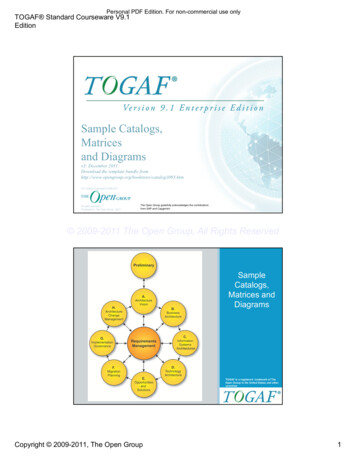
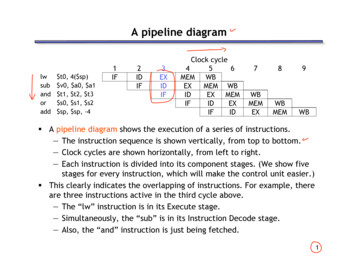
A pipeline diagramlwsubandoradd t0, 4( sp) v0, a0, a1 t1, t2, t3 s0, s1, s2 sp, sp, -41IF2IDIF3EXIDIFClock cycle456MEM WBEXMEM WBIDEX MEMIFIDEXIFID789WBMEMEXWBMEMWB A pipeline diagram shows the execution of a series of instructions.— The instruction sequence is shown vertically, from top to bottom.— Clock cycles are shown horizontally, from left to right.— Each instruction is divided into its component stages. (We show fivestages for every instruction, which will make the control unit easier.) This clearly indicates the overlapping of instructions. For example, thereare three instructions active in the third cycle above.— The “lw” instruction is in its Execute stage.— Simultaneously, the “sub” is in its Instruction Decode stage.— Also, the “and” instruction is just being fetched.1
Pipeline terminologylwsubandoradd t0, 4( sp) v0, a0, a1 t1, t2, t3 s0, s1, s2 sp, sp, -41IF2IDIF3EXIDIFfillingClock cycle456MEM WBEXMEM WBIDEX MEMIFIDEXIFIDfull789WBMEMEXWBMEMWBemptying The pipeline depth is the number of stages—in this case, five. In the first four cycles here, the pipeline is filling, since there are unusedfunctional units. In cycle 5, the pipeline is full. Five instructions are being executedsimultaneously, so all hardware units are in use. In cycles 6-9, the pipeline is emptying.2
Pipelined datapath and control Now we’ll see a basic implementation of a pipelined processor.— The datapath and control unit share similarities with both the singlecycle and multicycle implementations that we already saw.— An example execution highlights important pipelining concepts. In future lectures, we’ll discuss several complications of pipelining thatwe’re hiding from you for now.3
Pipelining concepts A pipelined processor allows multiple instructions to execute at once, andeach instruction uses a different functional unit in the datapath. This increases throughput, so programs can run faster.— One instruction can finish executing on every clock cycle, and simplerstages also lead to shorter cycle times.lwsubandoradd t0, 4( sp) v0, a0, a1 t1, t2, t3 s0, s1, s2 t5, t6, 01IF2IDIF3EXIDIFClock cycle456MEM WBEXMEM WBIDEX MEMIFIDEXIFID789WBMEMEXWBMEMWB4
Pipelined Datapath The whole point of pipelining is to allow multiple instructions to executeat the same time. We may need to perform several operations in the same cycle.— Increment the PC and add registers at the same time.— Fetch one instruction while another one reads or writes data.lwsubandoradd t0, 4( sp) v0, a0, a1 t1, t2, t3 s0, s1, s2 t5, t6, 01IF2IDIF3EXIDIFClock cycle456MEM WBEXMEM WBIDEX MEMIFIDEXIFID789WBMEMEXWBMEMWB Thus, like the single-cycle datapath, a pipelined processor will need toduplicate hardware elements that are needed several times in the sameclock cycle.5
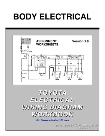
One register file is enough We need only one register file to support both the ID and WB stages.Readregister 1Readdata 1Readregister 2Readdata 2WriteregisterWritedataRegisters Reads and writes go to separate ports on the register file. Writes occur in the first half of the cycle, reads occur in the second half.6
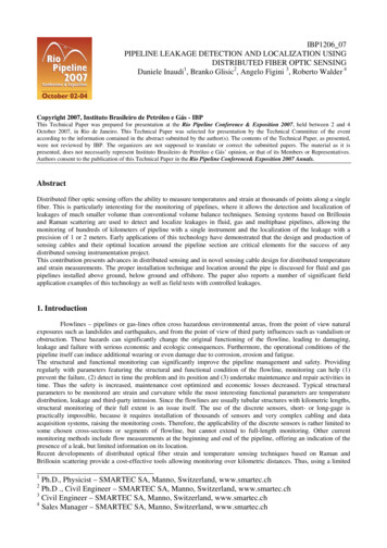
Single-cycle datapath, slightly rearranged10PCSrc4AddPCAddRegWriteReadregister 1Read ter 2Readdata 1Readdata 2WriteregisterWritedataInstr [15 - 0]Instr [20 - 16]Instr [15 - 11]Shiftleft ta1MemRead0017
What’s been changed? Almost nothing! This is equivalent to the original single-cycle datapath.— There are separate memories for instructions and data.— There are two adders for PC-based computations and one ALU.— The control signals are the same. Only some cosmetic changes were made to make the diagram smaller.— A few labels are missing, and the muxes are smaller.— The data memory has only one Address input. The actual memoryoperation can be determined from the MemRead and MemWritecontrol signals. The datapath components have also been moved around in preparationfor adding pipeline registers.8
Multiple cycles In pipelining, we also divide instruction execution into multiple cycles. Information computed during one cycle may be needed in a later cycle.— The instruction read in the IF stage determines which registers arefetched in the ID stage, what constant is used for the EX stage, andwhat the destination register is for WB.— The registers read in ID are used in the EX and/or MEM stages.— The ALU output produced in the EX stage is an effective address forthe MEM stage or a result for the WB stage. We added several intermediate registers to the multicycle datapath topreserve information between stages, as highlighted on the next slide.9
Registers added to the eMemReadReadregister erMemorydataregister1Readregister 2WriteregisterWritedataReaddata 1AReaddata UOp3ALUSrcB0MuxMuxSignextendShiftleft 21MemToReg10
Pipeline registers We’ll add intermediate registers to our pipelined datapath too. There’s a lot of information to save, however. We’ll simplify ourdiagrams by drawing just one big pipeline register between each stage. The registers are named for the stages they connect.IF/IDID/EXEX/MEMMEM/WB No register is needed after the WB stage, because after WB theinstruction is done.11
Pipelined riteReadregister 1Read ter 2Readdata 1Readdata 2WriteregisterWritedataInstr [15 - 0]Instr [20 - 16]Instr [15 - 11]Shiftleft ta1MemRead00112
Propagating values forward Any data values required in later stages must be propagated through thepipeline registers. The most extreme example is the destination register.— The rd field of the instruction word, retrieved in the first stage (IF),determines the destination register. But that register isn’t updateduntil the fifth stage (WB).— Thus, the rd field must be passed through all of the pipeline stages,as shown in red on the next slide. Why can’t we keep a single instruction register like we did in the multicycle data-path?13
The destination riteReadregister 1Read ter 2Readdata 1Readdata 2WriteregisterWritedataInstr [15 - 0]Instr [20 - 16]Instr [15 - 11]Shiftleft ta1MemRead00114
What about control signals? The control signals are generated in the same way as in the single-cycleprocessor—after an instruction is fetched, the processor decodes it andproduces the appropriate control values. But just like before, some of the control signals will not be needed untilsome later stage and clock cycle. These signals must be propagated through the pipeline until they reachthe appropriate stage. We can just pass them in the pipeline registers,along with the other data. Control signals can be categorized by the pipeline stage that uses them.15
Pipelined datapath and XMWBAddPCAddRegWriteReadregister 1Read ter 2Readdata 1Readdata 2WriteregisterWritedataInstr [15 - 0]Instr [20 - 16]Instr [15 - 11]Shiftleft ta1MemRead00116
What about control signals? The control signals are generated in the same way as in the single-cycleprocessor—after an instruction is fetched, the processor decodes it andproduces the appropriate control values. But just like before, some of the control signals will not be needed untilsome later stage and clock cycle. These signals must be propagated through the pipeline until they reachthe appropriate stage. We can just pass them in the pipeline registers,along with the other data. Control signals can be categorized by the pipeline stage that uses them.StageControl signals RegWriteMemToReg17
Pipelined datapath and XMWBAddPCAddRegWriteReadregister 1Read ter 2Readdata 1Readdata 2WriteregisterWritedataInstr [15 - 0]Instr [20 - 16]Instr [15 - 11]Shiftleft ta1MemRead00118
Notes about the diagram The control signals are grouped together in the pipeline registers, just tomake the diagram a little clearer. Not all of the registers have a write enable signal.— Because the datapath fetches one instruction per cycle, the PC mustalso be updated on each clock cycle. Including a write enable for thePC would be redundant.— Similarly, the pipeline registers are also written on every cycle, so noexplicit write signals are needed.19
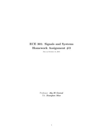
An example execution sequence Here’s a sample sequence of instructions to execute.addressesin decimal1000:1004:1008:1012:1016:lwsubandoradd 8, 4( 29) 2, 4, 5 9, 10, 11 16, 17, 18 13, 14, 0 We’ll make some assumptions, just so we can show actual data values.— Each register contains its number plus 100. For instance, register 8contains 108, register 29 contains 129, and so forth.— Every data memory location contains 99. Our pipeline diagrams will follow some conventions.— An X indicates values that aren’t important, like the constant field ofan R-type instruction.— Question marks ? indicate values we don’t know, usually resultingfrom instructions coming before and after the ones in our example.20
Cycle 1 (filling)IF: lw 8, 4( 29)ID: ?EX: ?MEM: ?WB: d1004PCAddShiftleft 2RegWrite (?)1000Read Instructionaddress[31-0]?Readregister 1?Readregister 2?Instructionmemory?Readdata 1?Read ?data 2?0MemWrite 1RegistersALUOp (?)? WritedataALUSrc (?)Signextend?RegDst (?)0Address?ReaddataMemRead (?)?MemToReg(?)?1?0?1?21
Cycle 2IF: sub 2, 4, 5ID: lw 8, 4( 29)EX: ?MEM: ?WB: d1008PCAddShiftleft 2RegWrite (?)1004Read Instructionaddress[31-0]29Readregister 1XReadregister 2?Instructionmemory?4Readdata 1Readdata 2129X?0MemWrite RegistersALUOp (?)? WritedataALUSrc (?)Signextend?8?X?RegDst (?)0Address?ReaddataMemRead (?)?MemToReg(?)?1?0?1?22
Cycle 3IF: and 9, 10, 11ID: sub 2, 4, 5EX: lw 8, 4( 29)MEM: ?WB: d1012PCAddShiftleft 2RegWrite (?)1008Read Instructionaddress[31-0]4Readregister 15Readregister 2?Instructionmemory?XReaddata 1104Read 105data 2129X0MemWrite ory1RegistersALUOp (add)? WritedataALUSrc (1)Signextend4X82XRegDst (0)0Address8ReaddataMemRead (?)?MemToReg(?)?1?0?1?23
Cycle 4IF: or 16, 17, 18ID: and 9, 10, 11EX: sub 2, 4, 5MEM: lw 8, 4( 29)WB: d1016PCAddShiftleft 2RegWrite (?)1012Read Instructionaddress[31-0]10Readregister 111Readregister 2?Instructionmemory?XReaddata 1110Read 111data 21041050MemWrite LURegistersALUOp (sub)ALUSrc (0)SignextendXXX92XRegDst d (1)899?1?0?1?24
Cycle 5 (full)IF: add 13, 14, 0ID: or 16, 17, 18EX: and 9, 10, 11MEM: sub 2, 4, 5WB:lw 8, 4( Add1020PCAddShiftleft 2RegWrite (1)1016Read Instructionaddress[31-0]17Readregister 118Readregister 28Instructionmemory99XReaddata 1117Read 118data 2110111WriteregisterWritedataALU0MemWrite (0)ZeroResult-11101RegistersALUOp (and)XXX169105 WritedataRegDst (1)09MemToReg(1)DatamemoryALUSrc (0)SignextendAddressReaddataMemRead (0)2X9911330819925
Cycle 6 (emptying)IF: ?ID: add 13, 14, 0EX: or 16, 17, 18MEM: and 9, 10, 11WB: sub 2, 4, d?PCAddShiftleft 2RegWrite (1)1020Read Instructionaddress[31-0]14Readregister 10Readregister 22Instructionmemory-1XReaddata 1Readdata 21140117118WriteregisterWritedataALU0MemWrite (0)ZeroResult1101191RegistersALUOp (or)XXX1316111 WritedataRegDst (1)016MemToReg(0)DatamemoryALUSrc (0)SignextendAddressReaddataX1MemRead (0)09126
Cycle 7IF: ?ID: ?EX: add 13, 14, 0MEM: or 16, 17, 18WB: and 9, 10, dd?PCAddShiftleft 2RegWrite (1)?Read Instructionaddress[31-0]?Readregister 1?Readregister 29Instructionmemory110Readdata 1?Read ?data tersX?X?13118 WritedataRegDst (1)0Address13MemToReg(0)DatamemoryALUOp (add)ALUSrc (0)SignextendMemWrite (0)ZeroReaddataMemRead (0)16XX111009111027
Cycle 8IF: ?ID: ?EX: ?MEM: add 13, 14, 0WB: or 16, 17, dd?PCAddShiftleft 2RegWrite (1)?Read Instructionaddress[31-0]?Readregister 1?Readregister 216Instructionmemory119Readdata 1?Read ?data 0RegDst (?)0?AddressMemToReg(0)DatamemoryALUOp (?)ALUSrc (?)SignextendMemWrite (0)ZeroWritedataReaddataMemRead (0)13XX1119016111928
Cycle 9IF: ?ID: ?EX: ?MEM: ?WB: add 13, 14, d?PCAddShiftleft 2RegWrite (1)?Read Instructionaddress[31-0]?Readregister 1?Readregister 213Instructionmemory114Readdata 1?Read ?data Dst (?)0?AddressMemToReg(0)DatamemoryALUOp (?)ALUSrc (?)SignextendMemWrite (?)ZeroWritedataReaddataMemRead (?)?XX1114013111429
That’s a lot of diagrams therelwsubandoradd t0, 4( sp) v0, a0, a1 t1, t2, t3 s0, s1, s2 t5, t6, 01IF2IDIF3EXIDIFClock cycle456MEM WBEXMEM WBIDEX MEMIFIDEXIFID789WBMEMEXWBMEMWB Compare the last nine slides with the pipeline diagram above.— You can see how instruction executions are overlapped.— Each functional unit is used by a different instruction in each cycle.— The pipeline registers save control and data values generated inprevious clock cycles for later use.— When the pipeline is full in clock cycle 5, all of the hardware unitsare utilized. This is the ideal situation, and what makes pipelinedprocessors so fast. Try to understand this example or the similar one in the book at the endof Section 6.3.30
Performance Revisited Assuming the following functional unit egWrite What is the cycle time of a single-cycle implementation?— What is its throughput? What is the cycle time of a ideal pipelined implementation?— What is its steady-state throughput? How much faster is pipelining?31
Ideal speeduplwsubandoradd t0, 4( sp) v0, a0, a1 t1, t2, t3 s0, s1, s2 sp, sp, -41IF2IDIF3EXIDIFClock cycle456MEM WBEXMEM WBIDEX MEMIFIDEXIFID789WBMEMEXWBMEMWB In our pipeline, we can execute up to five instructions simultaneously.— This implies that the maximum speedup is 5 times.— In general, the ideal speedup equals the pipeline depth. Why was our speedup on the previous slide “only” 4 times?— The pipeline stages are imbalanced: a register file and ALU operationscan be done in 2ns, but we must stretch that out to 3ns to keep theID, EX, and WB stages synchronized with IF and MEM.— Balancing the stages is one of the many hard parts in designing apipelined processor.32
The pipelining paradoxlwsubandoradd t0, 4( sp) v0, a0, a1 t1, t2, t3 s0, s1, s2 sp, sp, -41IF2IDIF3EXIDIFClock cycle456MEM WBEXMEM WBIDEX MEMIFIDEXIFID789WBMEMEXWBMEMWB Pipelining does not improve the execution time of any single instruction.Each instruction here actually takes longer to execute than in a singlecycle datapath (15ns vs. 12ns)! Instead, pipelining increases the throughput, or the amount of work doneper unit time. Here, several instructions are executed together in eachclock cycle. The result is improved execution time for a sequence of instructions, suchas an entire program.33
Instruction set architectures and pipelining The MIPS instruction set was designed especially for easy pipelining.— All instructions are 32-bits long, so the instruction fetch stage justneeds to read one word on every clock cycle.— Fields are in the same position in different instruction formats—theopcode is always the first six bits, rs is the next five bits, etc. Thismakes things easy for the ID stage.— MIPS is a register-to-register architecture, so arithmetic operationscannot contain memory references. This keeps the pipeline shorterand simpler. Pipelining is harder for older, more complex instruction sets.— If different instructions had different lengths or formats, the fetchand decode stages would need extra time to determine the actuallength of each instruction and the position of the fields.— With memory-to-memory instructions, additional pipeline stages maybe needed to compute effective addresses and read memory beforethe EX stage.34
Summary The pipelined datapath combines ideas from the single and multicycleprocessors that we saw earlier.— It uses multiple memories and ALUs.— Instruction execution is split into several stages. Pipeline registers propagate data and control values to later stages. The MIPS instruction set architecture supports pipelining with uniforminstruction formats and simple addressing modes. Next lecture, we’ll start talking about Hazards.35
3 Pipelined datapath and control Now we'll see a basic implementation of a pipelined processor. —The datapath and control unit share similarities with both the single-