Transcription
6-SeriesMultiparameterWater Quality SondesUser Manual6-Series:6600 V26600EDS V26920 V26820 V2600 OMS V2600XL600XLM600LS600R600QS
SAFETY NOTESTECHNICAL SUPPORT AND WARRANTY INFORMATIONContact information for technical support and warranty information on YSI’s EnvironmentalMonitoring Systems products can be found in Section 9, Warranty and Service Information.COMPLIANCEWhen using the YSI 6-Series sondes in a European Community (CE) country, please be awarethat electromagnetic compatibility (EMC) performance issues may occur under certainconditions, such as when the sonde is exposed to certain radio frequency fields.If you are concerned with these issues, consult the Declaration of Conformity that was enclosedwith your instrument. Specific conditions where temporary sensor problems may occur are listedin this document.The Declaration of Conformity for your instrument can be found in Appendix H, EMCPerformance. A similar document for YSI Model 650 is located at the end of Section 3, 650MDS.SPECIFICATIONSFor general specifications for all YSI Environmental Monitoring Systems products included inthis manual, please see Appendix O, Specifications.GENERAL SAFETY CONSIDERATIONSFor Health and Safety issues concerning the use of the calibration solutions with the sondes,please see Appendix A, Health and Safety.NOTICEInformation contained in this manual is subject to change without notice. Effort has been made tomake the information contained in this manual complete, accurate, and current. YSI shall not beheld responsible for errors or omissions in this operations manual.WARNING:When caring for your sonde, remember that the sonde is sealed at the factory, and there is never aneed to gain access to the interior circuitry of the sonde. In fact, if you attempt to disassemble thesonde, you would void the manufacturer's warranty.
TABLE OF CONTENTSSECTION 1 INTRODUCTION1.1 ABOUT YSI1.2 HOW TO USE THIS MANUAL1.3 UNPACKING AND INSPECTION1-11-11.2SECTION 2 SONDES2.1 GETTING STARTED2.2 CONNECTING YOUR SONDE2.3 PREPARING THE SONDE FOR USE2.4 ECOWATCH FOR WINDOWS – GETTING STARTED2.5 SONDE SOFTWARE SETUP2.6 GETTING READY TO CALIBRATE2.7 TAKING READINGS2.8 USING ECOWATCH TO UPLOAD AND ANALYZE DATA2.9 SONDE MENU2.10 CARE, MAINTENANCE, AND ON 3 650 MDS DATA LOGGER3.1 INTRODUCTION3.2 GETTING STARTED3.3 SETTING UP THE 6503.4 SONDE MENU INTERFACE3.5 LOGGING DATA WITH THE 6503.6 MANAGING 650 FILES3.7 UPLOADING DATA FROM SONDES3.8 USING GPS WITH 6503.9 USING THE 650 BAROMETER3.10 UPGRADING 650 SOFTWARE3.11 TROUBLESHOOTING3.12 FERRITE BEAD INSTALLATION3.13 SAFETY CONSIDERATIONS3.14 650 MDS 553-563-573-583-61SECTION 4 ECOWATCH FOR WINDOWS4.1 INTRODUCTION4.2 DATA ACQUISITION AND ANALYSIS4.3 ECOWATCH MENU4-14-74-12SECTION 5 PRINCIPLES OF OPERATION5.1 CONDUCTIVITY5.2 SALINITY5.3 TOTAL DISSOLVED SOLIDS (TDS)5.4 OXIDATION REDUCTION POTENTIAL (ORP)5.5 pH5.6 DEPTH AND LEVEL5.7 TEMPERATURE5.8 DISSOLVED OXYGEN RAPID PULSE5.9 DISSOLVED OXYGEN ROX OPTICAL5.10 NITRATE5.11 AMMONIUM AND AMMONIA5.12 CHLORIDE5.13 -17
5.14 CHLOROPHYLL5.15 RHODAMINE5.16 PHYCOCYANIN-CONTAINING BLUE-GREEN ALGAE5.17 PHYCOERYTHRIN-CONTAINING BLUE-GREEN ALGAE5.18 FLOW5-215-285-315-375-42SECTION 6 TROUBLESHOOTING6.1 CALIBRATION ERRORS6.2 SONDE COMMUNICATION PROBLEMS6.3 SENSOR PERFORMANCE PROBLEMS6-16-26-3SECTION 7 COMMUNICATION7.1 OVERVIEW7.2 HARDWARE INTERFACE7.3 RS-232 INTERFACE7.4 SDI-12 INTERFACE7-17-17-27.2SECTION 8 UPGRADING SONDE FIRMWARE8.1SECTION 9 WARRANTY AND SERVICE INFORMATION9.1 LIMITATIONS OF WARRANTY9.2 AUTHORIZED SERVICE CENTERS9.3 CLEANING INSTRUCTIONS9.4 PACKING INSTRUCTIONS9.5 PRODUCT RETURN FORM9-19-29-29-29-4APPENDIX A HEALTH AND SAFETYA-1APPENDIX B REQUIRED NOTICEB-1APPENDIX C ACCESSORIES AND CALIBRATION STANDARDSC-1APPENDIX D SOLUBILITY AND PRESSURE/ALTITUDE TABLESD-1APPENDIX E TURBIDITY MEASUREMENTSE-1APPENDIX F FLOWF-1APPENDIX G USING VENTED LEVELG-1APPENDIX H EMS PERFORMANCEH-1APPENDIX I CHLOROPHYLL MEASUREMENTSI-1APPENDIX J PERCENT AIR SATURATIONJ-1APPENDIX K PAR SENSORK-1APPENDIX L PROTECTIVE ZINC ANODEL-1APPENDIX M ROX OPTICAL DO SENSORM-1APPENDIX N NMEA APPLICATIONSN-1APPENDIX O SPECIFICATIONSO-1
IntroductionSection 1SECTION 1 INTRODUCTION1.1 ABOUT YSI INCORPORATEDFrom a three-man partnership in the basement of the Antioch College science building in 1948, YSI hasgrown into a commercial enterprise designing and manufacturing precision measurement sensors andcontrol instruments for users around the world. Although our range of products is broad, we focus on threemajor markets: water testing and monitoring, health care, and bioprocessing.In the 1950s, Hardy Trolander and David Case made the first practical electronic thermometer using athermistor. This equipment was developed to supply Dr. Leland Clark with a highly sensitive and precisetemperature sensor for the original heart-lung machine. The collaboration with Dr. Clark has been criticalto the success of the company. In the 1960s, YSI refined a Clark invention, the membrane coveredpolarographic electrode, and commercialized oxygen sensors and meters which revolutionized the waydissolved oxygen was measured in wastewater treatment plants and environmental water. Today,geologists, biologists, environmental enforcement personnel, officials of water utilities and fish farmersrecognize us as the leader in dissolved oxygen measurement.In the 1970s, YSI again worked with Clark to commercialize one of his many inventions, the enzymemembrane. This development resulted in the first practical use of a biosensor, in the form of a membranebased on immobilized glucose oxidase, to measure blood sugar accurately and rapidly. In the next fewyears, this technology was extended to other enzymes, including lactate oxidase, for applications inbiotechnology, health care, and sports medicine.In the early 1990s, YSI launched a line of multi-parameter water monitoring systems to address theemerging need to measure non-point source pollution. Today we have thousands of instruments in the fieldthat operate with the push of a button, store data in memory, and communicate with computers. Theseinstruments (described in this manual) are ideal for profiling and monitoring water conditions in industrialand wastewater effluents, lakes, rivers, wetlands, estuaries, coastal waters, and monitoring wells. If theinstrument has ‘on board’ battery power, it can be left unattended for weeks at a time with measurementparameters sampled at the user’s setup interval and data securely saved in the unit's internal memory. Thefast responses of YSI’s sensors make the systems ideal for vertical profiling, and the small size of some oursondes allows them to fit down 2-inch diameter monitoring wells. All of YSI’s multi-parameter systemsfeature either the YSI-patented Rapid Pulse Dissolved Oxygen Sensor, which exhibits low-stirringdependence and provides accurate results without an expensive, bulky, and power-intensive stirrer or an ROXoptical dissolved oxygen sensor which exhibits no flow dependence and is extremely stable in long-termdeployments.YSI has established a worldwide network of selling partners in over 50 countries that includes laboratorysupply dealers, manufacturers' representatives, and YSI’s sales force. A subsidiary, YSI UK, distributesproducts in the United Kingdom, a sales office in Hong Kong supports YSI’s distribution partners in AsiaPacific, and YSI Japan supports distribution partners in Japan.Through an employee stock ownership plan (ESOP), every employee is one of the owners. In 1994, theESOP Association named YSI the ESOP Company of the Year. YSI is proud of its products and arecommitted to meeting or exceeding customers' expectations.1.2 HOW TO USE THIS MANUALThe manual is organized to let you quickly understand and operate the YSI 6-Series environmentalmonitoring systems. However, it cannot be stressed too strongly that informed and safe operation is morethan just knowing which buttons to push. An understanding of the principles of operation, calibrationYSI IncorporatedEnvironmental Monitoring Systems Manual1-1
IntroductionSection 1techniques, and system setup is necessary to obtain accurate and meaningful results. Thorough reading andunderstanding of this manual is essential to proper operation.Because of the many features, configurations and applications of these versatile products, some sections ofthis manual may not apply to the specific system you have purchased.If you have any questions about this product or its application, please contact YSI’s Technical SupportGroup or authorized dealer for assistance. See Section 9, Warranty and Service Information for contactinformation.1.3 UNPACKING AND INSPECTIONInspect the outside of the shipping box for damage. If any damage is detected, contact your shipping carrierimmediately. Remove the equipment from the shipping box. Some parts or supplies are loose in theshipping box so check the packing material carefully. Check off all of the items on the packing list andinspect all of the assemblies and components for damage.If any parts are damaged or missing, contact your YSI representative immediately. If you purchased theequipment directly from YSI, or if you do not know from which YSI representative your equipment waspurchased, refer to Section 8, Warranty and Service Information for contact information.YSI IncorporatedEnvironmental Monitoring Systems Manual1-2
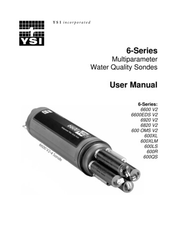
SondesSection 2SECTION 2 SONDES2.1 GETTING STARTEDThe 6-Series Environmental Monitoring Systems from YSI are multi-parameter, water qualitymeasurement, and data collection systems. They are intended for use in research, assessment, andregulatory compliance applications. Section 2 concentrates on sondes and how to operate them duringdifferent applications. A sonde is a torpedo-shaped water quality monitoring device that is placed in thewater to gather water quality data. Sondes may have multiple probes. Each probe may have one or moresensors that read water quality data.The following list contains parameters that your sonde may measure. See Appendix O, Specifications forthe specific parameters of each sonde. Rapid Pulse Polarographic Dissolved OxygenROX Optical Dissolved OxygenConductivitySpecific ConductanceSalinityTotal Dissolved bidityChlorophyllRhodamine WTPhycocyanin-Containing Blue-green AlgaePhycoerythrin-Containing Blue-green AlgaeNitrate-NAmmonia-NAmmonium-NChlorideThis section is designed to quickly familiarize you with the hardware and software components of thesondes and their accessories. You will then proceed to probe installations, cable connections, softwareinstallation and finally basic communication with your Sonde. Diagrams, menu flow charts and basicwritten instructions will guide you through basic hardware and software setup.YSI IncorporatedEnvironmental Monitoring Systems Operations Manual2-1
SondesSection 22.2 CONNECTING YOUR SONDEThere are a number of ways in which you may connect the sondes to various computers, data collectiondevices and VT-100 terminal emulators. To utilize the configuration that will work best for yourapplication, make sure that you have all of the components that are necessary. The following list anddiagrams (Figures 1-4) are a few possible configurations. Sonde to Lab Computer (recommended for initial setup)Sonde to Data Collection PlatformSonde to Portable ComputerSonde to YSI 650 MDS Display/LoggerFigure 1YSI IncorporatedEnvironmental Monitoring Systems Operations Manual2-2
SondesSection 2Figure 2Sonde to Data Collection PlatformDCP6096 MS-8 Adapter with Flying LeadsMS-8Field CableYou will need. -SondeYSI6920 Sonde Field Cable 6096 Adapter with leads Data Collection PlatformFigure 3YSI IncorporatedEnvironmental Monitoring Systems Operations Manual2-3
SondesSection 2Figure 4Sonde to 650 Display/LoggerYSEnvir onmentalMonitoringSystems610-DM650 MDSMS-8You will need.Field Cable Sonde Field Cable-SondeYSI6920 650 MDS Display/LoggerYSI 650 operates on C-cells or rechargeable batteries.YSI IncorporatedEnvironmental Monitoring Systems Operations Manual2-4
SondesSection 22.3 PREPARING THE SONDE FOR USETo prepare the sonde for calibration and operation, you need to install probes (sensors) into the connectorson the sonde bulkhead. In addition to probe installation, you need to install a new membrane on the YSI6562 DO Probe if you are using this item. It is recommended that you install the DO membrane beforeinstalling the probe onto the bulkhead. For membrane changes in the future, you may be able to performthis operation without removing the DO probe. This will largely depend on whether the other installedprobes interfere with your ability to install a membrane. The next step is providing power for the sondes,through batteries or line power, and then connecting a field cable. The four steps necessary for getting yoursonde ready for use are listed below.Step 1Step 2Step 3Step 4Installing the Dissolved Oxygen Membrane – Section 2.3.1Installing the Probes – Section 2.3.2Supplying Power – Section 2.3.3Connecting a Field Cable – Section 2.3.42.3.1 STEP 1 - INSTALLING THE DISSOLVED OXYGEN MEMBRANENote: If you are using a ROX Optical DO sensor for your applications, please skip to Section 2.3.2 atthis time.The 6562 Rapid Pulse Polarographic DO probe is shipped with a protective dry membrane on the sensor tipheld in place by an O-ring. Remove the O-ring and membrane. Handle the probe with care. It is veryimportant not to scratch or contaminate the sensor tip. See Section 2.10.2, Probe Care and Maintenance,for information on how often the membrane should be replaced.Unpack the YSI 6562 DO Probe Kit and follow the instructions below.Open the membrane kit and prepare the electrolyte solution. Dissolve the KCl in the dropper bottle byfilling it to the neck with deionized or distilled water and shaking until the solids are fully dissolved. Afterthe KCl is dissolved, wait a few minutes until the solution is free of bubbles.Figure 51.Figure 6ADD DI OR DISTILLEDWATER2.DRY MEMBRANEPROTECTIVE CAPThe DO membrane can be installed with the DO probe either free or installed in the sonde. Both methodsare described in detail below. CAUTION: If you install the membrane with the probe not installed inthe sonde, be sure that the protective cap is installed on the probe end away from the sensor face toensure that the connector is not contaminated with electrolyte.YSI IncorporatedEnvironmental Monitoring Systems Operations Manual2-5
SondesSection 2DO MEMBRANE INSTALLATION WITH THE PROBE NOT INSTALLED IN THESONDERemove the protective cap and the dry membrane from the YSI 6562 Dissolved Oxygen probe.Make sure that the protective cap is installed on the connector end of the probe. Do not allow theelectrolyte solution to wet the probe‟s connector and O-ring seal areas. This solution is extremely corrosiveto the connector and is difficult to remove.Before using any electrolyte, wrap a clean, dry paper towel around the capped probe to catch any spilledelectrolyte. Hold the probe in a vertical position and apply a few drops of KCl solution to the tip. The fluidshould completely fill the small moat around the electrodes and form a meniscus on the tip of the sensor.Be sure no air bubbles are stuck to the face of the sensor. If necessary, shake off the electrolyte and startover.Figure 7Secure a membrane between your left thumb and the probe body.Always handle the membrane with care, touching it only at theends.With the thumb and forefinger of your right hand, grasp the freeend of the membrane. With one continuous motion, gently stretchit up, over, and down the other side of the sensor. The membraneshould conform to the face of the sensor.34Secure the end of the membrane under the forefinger of your lefthand.Roll the O-ring over the end of the probe, being careful not totouch the membrane surface with your fingers. There should be nowrinkles or trapped air bubbles. Small wrinkles may be removedby lightly tugging on the edges of the membrane. If bubbles arepresent, remove the membrane and repeat steps 3-8.Trim off any excess membrane with a sharp knife or scissors.Rinse off any excess KCl solution, but be careful not to get anywater in the connector.If you are concerned that electrolyte may have dripped onto the Oring seal area, probe connector, or bulkhead connectors, rub thearea clean with paper towels wetted with Deionized water and thendry the affected area with a final dry towel, compressed air blasts,or rinse with fresh alcohol.5678NOTE: You may find it more convenient to mount the probe vertically in a vise with rubber jaws whileapplying the electrolyte and membrane to the sensor tip.YSI IncorporatedEnvironmental Monitoring Systems Operations Manual2-6
SondesSection 2DO MEMBRANE INSTALLATION WITH THE PROBE INSTALLED IN THE SONDESecure the sonde in a vertical position using a vise or a clamp and ring stand such that the sensors areupright. Remove the probe guard from the sonde.Remove the old DO membrane and clean the probe tip with water and lens cleaning tissue. Make sure toremove any debris or deposits from the O-ring groove.Using the dropper bottle of electrolyte supplied, place electrolyte on the DO probe tip until a high meniscusis formed as shown in Figure 8 below.Figure 8Figure 9Hold the membrane so that all four corners are supported, but do not stretch the membrane laterally.Position the membrane over the probe, keeping it parallel to the probe face as shown in Figure 9 above.Using one continuous downward motion, stretch the membrane over the probe face as shown. See Figure10 below. Do not hesitate to stretch the membrane.Figure 10Figure 11Install a new O-ring by placing one side of the O-ring in the groove and rolling into place across themembrane and into the groove on the opposite side of the probe face. Avoid touching the probe face withYSI IncorporatedEnvironmental Monitoring Systems Operations Manual2-7
SondesSection 2your fingers. Once the O-ring is in position, squeeze it every 90 degrees to equalize the tension. SeeFigure 11 above. DO NOT USE GREASE OR LUBICANT OF ANY KIND ON THE O-RING.Using a hobby knife or a scalpel, trim the excess Teflon from the membrane, making your cut about 1/8inch below the O-ring as shown in Figure 12 below. A razor blade can be used for the cut if no knife orscalpel is available.Figure 12Figure 13If the installation has been done properly, the finished product should have no bubbles, wrinkles, or tears asshown in Figure 13 above.NOTE: Observe the following cautions to assure that your membrane installation is proper: Secure the sonde tightly so that it will not move during membrane installation. Wash hands before installation and do not allow finger oils or O-ring lubricant to touch the probe faceor the membrane. Use caution when replacing the probe guard that you do not touch the membrane. If you suspect thatthe membrane has been damaged, replace it immediately.2.3.2 STEP 2 - INSTALLING THE PROBESRemove the calibration cup from your sonde by hand as shown in Figure 14, to expose the bulkhead.Figure 14TRANSPORT CUPBULKHEAD WITHPROBE PORT PLUGSYSI IncorporatedEnvironmental Monitoring Systems Operations Manual2-8
SondesSection 2REMOVING THE PORT PLUGSUsing the long extended end of the probe installation tool supplied in the YSI 6570Maintenance Kit, remove the port plugs. Save all the port plugsFigure 15for possible future use.There are a variety of probe options for the sondes. Figures 15, 16 and 17illustrate the uses of the common tool for port plug removal.Note that this tool will also be used to install the various probes.If the tool is misplaced or lost, you may use 7/64” and 9/64” hex keys assubstitutes.DO, COND., &pH/ORP PORTPLUGSOPTICPORT PLUGINSTALLATIONTOOLINSTALLATIONTOOLFigure 16Figure 17Figure 18NOTE: You may need pliers to remove the ISE portplugs, but do not use pliers to tighten the ISE probes.Hand-tighten only.ISE PORT PLUGNow refer to Figures 19-24 to find the probe locations inyour sonde.PLIERS(SLIP JAWS)YSI IncorporatedEnvironmental Monitoring Systems Operations Manual2-9
SondesSection 2600XL & 600XLM SONDE BULKHEAD3 Port Sonde: 1 Rapid Pulse DO, 1 Conductivity/Temperature, and 1 pH/ORPFigure 19 6562 Dissolved oxygen probe 3-pin connector6560 Conductivity/Temperature 6-pin connector6561 pH probe 4 pin connector6565 Combo pH/ORP probe 4 pin RE6560ALL ISEPROBES6600V2-2 SONDE BULKHEAD8 Port Sonde: 1 Rapid Pulse DO, 1 Conductivity/Temperature, 2 Optical, 3 ISE, 1 pH/ORPFigure 20A 6562 Dissolved oxygen probe 3-pin connector6560 Conductivity/Temperature 6-pin connector6561 or 6561FG pH probe 4 pin connector6565 or 6565FG pH/ORP probe 4 pin connector6566 Fouling Resistant pH/ORP probe 4 pin connector6882 Chloride Probe leaf spring connector6883 Ammonium Probe leaf spring connector6884 Nitrate Probe leaf spring connector6026 Turbidity Probe, Wiping 8 pin connector6136 Turbidity Probe, Wiping 8 pin connector6025 Chlorophyll Probe, Wiping 8 pin connector6130 Rhodamine WT Probe, Wiping 8 pin connector6150 Optical Dissolved oxygen probe 8 pin connector6131 PC-Blue-green Algae probe 8 pin connector6132 PE-Blue-green Algae probe 8 pin connectorDissolved OxygenISE‟sOptic TOptic CCond./Temp.YSI IncorporatedISE‟sEnvironmental Monitoring Systems Operations ManualpH/ORPISE‟s2-10
SondesSection 26600EDS V2-2 SONDE BULKHEAD5 Port Sonde: 1 Rapid Pulse DO, 1 Conductivity/Temperature, 2 Optical, 1 pH/ORPFigure 20B 6562 Dissolved oxygen probe 3-pin connector6560 Conductivity/Temperature 6-pin connector6561 or 6561FG pH probe 4 pin connector6565 or 6565FG pH/ORP probe 4 pin connector6566 Fouling Resistant pH/ORP probe 4 pin connector6026 Turbidity Probe, Wiping 8 pin connector6136 Turbidity Probe, Wiping 8 pin connector6025 Chlorophyll Probe, Wiping 8 pin connector6130 Rhodamine WT Probe, Wiping 8 pin connector6150 Optical Dissolved oxygen probe 8 pin connector6131 PC-Blue-green Algae probe 8 pin connector6132 PE-Blue-green Algae probe 8 pin connectorRapid Pulse DO – 3 pinCond//Temp – 6 pinpH/ORP – 4 pin6600V2-4 SONDE BULKHEAD6 Port Sonde: 1 Conductivity/Temperature, 4 Optical, 1 pH/ORPCond/Temp – 6 pinFigure 20C 6560 Conductivity/Temperature 6-pin connector6561 or 6561FG pH probe 4 pin connector6565 or 6565FG pH/ORP probe 4 pin connector6566 Fouling Resistant pH/ORP probe 4 pin connector6026 Turbidity Probe, Wiping 8 pin connector6136 Turbidity Probe, Wiping 8 pin connector6025 Chlorophyll Probe, Wiping 8 pin connector6130 Rhodamine WT Probe, Wiping 8 pin connector6150 Optical Dissolved oxygen probe 8 pin connector6131 PC-Blue-green Algae probe 8 pin connector6132 PE-Blue-green Algae probe 8 pin connectorpH/ORP – 4 pinYSI IncorporatedEnvironmental Monitoring Systems Operations Manual2-11
SondesSection 26820V2-1 & 6920V2-1 SONDE BULKHEADS7 Port Sonde: 1 Rapid Pulse DO, 1 Conductivity/Temperature, 1 Optical, 1 pH/ORP, 3 ISEFigure 21A 6562 Dissolved oxygen probe 3-pin connector6560 Conductivity/Temperature 6-pin connector6561 or 6561FG pH probe 4 pin connector6565 or 6565FG pH/ORP probe 4 pin connector6566 Fouling Resistant pH/ORP probe 4 pin connector6882 Chloride Probe leaf spring connector6883 Ammonium Probe leaf spring connector6884 Nitrate Probe leaf spring connector6026 Turbidity Probe, Wiping 8 pin connector6136 Turbidity Probe, Wiping 8 pin connector6025 Chlorophyll Probe, Wiping 8 pin connector6130 Rhodamine WT Probe, Wiping 8 pin connector6150 Optical Dissolved oxygen probe 8 pin connector6131 PC-Blue-green Algae probe 8 pin connector6132 PE-Blue-green Algae probe 8 pin UNTINGSCREWOPTICAL3ISE354ISE5ISE46820V2-2 & 6920V2-2 SONDE BULKHEADS5 Port Sonde: 1 Conductivity/Temperature, 2 Optical, 1 pH/ORP, 1 ISEFigure 21B 6560 Conductivity/Temperature 6-pin connector6561 or 6561FG pH probe 4 pin connector6565 or 6565FG pH/ORP probe 4 pin connector6566 Fouling Resistant pH/ORP probe 4 pin connector6882 Chloride Probe leaf spring connector6883 Ammonium Probe leaf spring connector6884 Nitrate Probe leaf spring connector6026 Turbidity Probe, Wiping 8 pin connector6136 Turbidity Probe, Wiping 8 pin connector6025 Chlorophyll Probe, Wiping 8 pin connector6130 Rhodamine WT Probe, Wiping 8 pin connector6150 Optical Dissolved oxygen probe 8 pin connector6131 PC-Blue-green Algae probe 8 pin connector6132 PE-Blue-green Algae probe 8 pin connectorYSI IncorporatedEnvironmental Monitoring Systems Operations Manual2-12
SondesSection 2600LS BULKHEADFigure 21CIf are working with a 600LS, all sensors will have been installedat the factory.ConductivityDepthTemperature600R BULKHEADFigure 22If are working with a 600R sonde, your instrumentwill arrive with the probes installed.TEMPERATUREpH GLASSpH REFERENCE6850CONDUCTIVITYDISSOLVEDOXYGEN600QS BULKHEADFigure 23If are working with a 600QS sonde, yourinstrument will arrive with the probes installed.TEMPERATUREpH GLASS/ORPpH REFERENCE6850CONDUCTIVITYDISSOLVEDOXYGENYSI IncorporatedEnvironmental Monitoring Systems Operations Manual2-13
SondesSection 2600 OMS V2-1 BULKHEADFigure 24The conductivity sensor (module/port) for the600 OMS V2-1 is factory installed. Optical probes(turbidity, chlorophyll, rhodamine WT, ROXoptical DO, BGA-PC, and BGA-PE) arethreaded into the optical port on the bottomof the sonde by the user.Conductivity PortOptical PortTemperature SensorLUBRICATE O-RINGSApply a thin coat of O-ring lubricant, supplied in the YSI 6570 Maintenance Kit, to the O-rings on theconnector side of each probe that is to be installed.Figure 25CAUTION: Make sure that there are NO contaminantsbetween the O-ring and the probe. Contaminants that are presentunder the O-ring may cause the O-ring to leakwhen the sonde is deployed.LUBRICATE O-RINGSNOTE: Before installing any probe into the sonde bulkhead, be sure that the probe port is free ofmoisture. If there is moisture present, you may use a can of compressed air to blow out the remainingmoisture.YSI IncorporatedEnvironmental Monitoring Systems Operations Manual2-14
SondesSection 2INSTALLING THE TURBIDITY, CHLOROPHYLL, RHODAMINE WT , BGA-PHYCOCYANIN, BGAPHYCOERYTHRIN, AND ROX OPTICAL DISSOLVED OXYGEN PROBESIf you are using any of optical probes listed, it is recommended that the optical sensors be installed first. Ifyou are not installing one of these probes, do not remove the port plug, and go on to the next probeinstallation.Figure 26All optical probes, 6136 turbidity, 6025 chlorophyll, 6130OPTICRhodamine WT, 6131 Phycocyanin Blue-green algae, 6132PROBEPhycoerythrin-Blue-green algae, and 6150 ROX OpticalDO are installed in the same way. Install the probe into thecenter port, seating the pins of the two connectors beforeyou begin to tighten. Tighten the probe nut to the bulkheadINSTALLATIONusing the short extended end of the tool supplied with theTOOLprobe. Do not over-tighten.CAUTION: Be careful not to cross-thread the probe nut.The YSI 6820V2-1 and 6920V2-1 sondes can accept a single turbidity, chlorophyll, Rhodamine WT, BGAPC, BGA-PE, or ROX DO probe. The 6600V2-2, 6600EDS V2-2, 6820V2-2, and 6920V2-2 sondes canaccept and utilize two of the six optical sensors at the same time. The two optical ports of these sondes arelabeled “T” and “C” on the sonde bulkhead. Each port can accept any of the six sensors so be sure toremember which sensor was installed in which port so that you will later be able to set up the sondesoftware correctly. The 6600V2-4 sonde can accept and utilize four of the six optical sensors at the sametime. The four optical ports of this sonde are labeled “T” , “C”, “B”, and “O” on the sonde bulkhead. Eachport can accept any of the six sensors so be sure to remember which sensor was installed in which port sothat you will later be able to set up the sonde software correctly.INSTALLING THE 6562 RAPID PULSE DISSOLVED OXYGEN PROBE, CONDUCTIVITY/TEMP ANDpH/ORP PROBESFigure 27Insert the probe into the correct port and gently rotate theprobe until the two connectors align.DO PROBEThe probes have slip nuts that require a small probeinstallation tool to tighten the probe. With the connectorsaligned, screw down the probe nut using the long extendedend of the probe installation tool. Do not over-tighten.CAUTION: Do not cross thread the probe nut.YSI IncorporatedPROBE INSTALLATIONTOOLEnvironmental Monitoring Systems Operations Manual2-15
SondesSection 2INSTALLING THE ISE PROBESFigure 28The Ammonium, Nitrate and Chloride ISE probes do not have slipnuts and should be installed without tools. Use only your fingersto tighten. Any ISE probe can be installed in any of the three portslabeled “3”, “4”, and “5” on the sonde bulkhead of the 6820V2-1,6920V2-1, and 6600V2-2 sondes or the single ISE port on the6820V2-2 and 6920V2-2 bulkheads. Be sure to rememberwhich sensor was installed in which port so that you will later beable to set up the sonde software correctly.ISE PROBEINSERT ISE PROBE,SCREW IN AND TIGHTEN WITH FINGERS.Figure 29IMPORTANT: Make sure that the probe nut or probe bodyof the ISE probes are seated directly on the sonde bulkhead.This will ensure that connector seals will not allow leakage.PROBE BODY TO SEATON BULKHEADISE PROBEDO PROBEPROBE NUT TO SEATON BULKHEADINSTALLING THE PROBE GUARDIncluded with each sonde is a probe guard. The probe guard protects the probes during calibration andmeasurement procedures. Once the probes are installed, install this guard by aligning it with the threads onthe bulkhead and turn the guard clockwise until secure.CAUTION: Be careful not to damag
6-Series Multiparameter Water Quality Sondes . User Manual . 6-Series: 6600 V2 . 6600EDS V2 . 6920 V2 . 6820 V2 . 600 OMS V2 . 600XL . 600XLM . 600LS