Transcription
Dell Compellent StorageCenter Fibre Channel StorageArrays WithMicrosoft Windows ServerFailover ClustersHardware Installationand TroubleshootingGuide
Notes, Cautions, and WarningsNOTE: A NOTE indicates important information that helps you make better useof your computer.CAUTION: A CAUTION indicates potential damage to hardware or loss of dataif instructions are not followed.WARNING: A WARNING indicates a potential for property damage, personalinjury, or death.Information in this publication is subject to change without notice. 2011 Dell Inc. All rights reserved.Reproduction of these materials in any manner whatsoever without the written permission of DellInc. is strictly forbidden.Trademarks used in this text: Dell , the DELL logo, PowerEdge , PowerVault , andCompellent are trademarks of Dell Inc. Microsoft , Windows , Windows Server , and ActiveDirectory are either trademarks or registered trademarks of Microsoft Corporation in the UnitedStates and/or other countries.Other trademarks and trade names may be used in this publication to refer to either the entitiesclaiming the marks and names or their products. Dell Inc. disclaims any proprietary interest intrademarks and trade names other than its own.2011 - 07Rev A00
Contents1Introduction . . . . . . . . . . . . . . . . . . . . . . .Cluster Solution. . . . . . . . . . . . . . . . . . . . . .6. . . . . . . . . . . . . . . . . . . .6Cluster Storage . . . . . . . . . . . . . . . . . . .Other Documents You May Need2. . . . . . . . . . . . .Cabling Your Cluster Hardware . . . . . . .Cabling the Mouse, Keyboard, and MonitorCabling the Power Supplies .7911. . . . . .11. . . . . . . . . . . . . .11Cabling Your Cluster for Public and Private Networks . . . . . . . . . . . . . . . . . . .12Cabling the Public Network. . . . . . . . . . . .13Cabling the Private Network. . . . . . . . . . . .13. . . . . . . . . . . . . . . . . . . .14NIC TeamingCabling the Storage System35. . . . . . . . . . . . .Cluster Hardware RequirementsCluster Nodes .5. . . . . . . . . . . . . . .Preparing Your Systems for Clustering . . . . . . . . . . . . . . . . . . . . . . .25. . . . . . . . . . . .25. . . . . . . . . . . . . . . . . .27Cluster Configuration Overview .Installation Overview15Installing the Fibre Channel HBAs. . . . . . . . . . .Contents273
Installing the Fibre Channel HBA Drivers . . . . .28. . . . . . .28. . . . . . . . .29. . . . . . . . . . . . .30. . . . . . . . . . . . . . . . . .31Implementing Zoning on a Fibre Channel Switched Fabric . . . . . . . . . . . . . .Installing and Configuring the Shared Storage System . . . . . . . . . . . . .Setting Up the ControllersCreate a Server .Create a Server Cluster . . . . . . . . . . . . . .Create a Volume for the Server Cluster.Optional Storage Features33. . . . . . . . . . . . .34Installing and Configuring a Failover Cluster .A Troubleshooting .B Zoning Configuration Form4Contents. . . . . . . . . . . . . . . . . . . . . .C Cluster Data Form32. . . . . .3537. . . . . . . . . .43. . . . . . . . . . . . . . . . .45
1IntroductionA Dell Failover Cluster combines specific hardware and software componentsto provide enhanced availability for applications and services that are run onthe cluster. A Failover Cluster is designed to reduce the possibility of anysingle point of failure within the system that can cause the clusteredapplications or services to become unavailable. It is recommended that youuse redundant components like server and storage power supplies,connections between the nodes and the storage array(s), and connections toclient systems or other systems in a multi-tier enterprise applicationarchitecture in your cluster.This document provides information to configure your Dell CompellentStorage Center Fibre Channel storage array with one or more FailoverClusters. It provides information on specific configuration tasks that enableyou to deploy the shared storage for your cluster.For more information on deploying your cluster with Microsoft WindowsServer 2008 operating systems, see the Dell Failover Clusters with MicrosoftWindows Server 2008 Installation and Troubleshooting Guide atsupport.dell.com/manuals.For a list of recommended operating systems, hardware components, anddriver or firmware versions for your Failover Cluster, see the Dell ClusterConfiguration Support Matrices at dell.com/ha.Cluster SolutionYour cluster implements a minimum of two nodes to a maximum of sixteennodes and provides the following features: 8 Gbps and 4 Gbps Fibre Channel technology. High availability of resources to network clients. Redundant paths to the shared storage. Failure recovery for applications and services. Flexible maintenance capabilities, allowing you to repair, maintain, orupgrade a node or storage system without taking the entire cluster offline.Introduction5
Implementing Fibre Channel technology in a cluster provides the followingadvantages: Flexibility—Fibre Channel allows a distance of up to 10 km betweenswitches without degrading the signal. Availability—Fibre Channel components use redundant connectionsproviding multiple data paths and greater availability for clients. Connectivity—Fibre Channel allows more device connections than SmallComputer System Interface (SCSI). Because Fibre Channel devices arehot-pluggable, you can add or remove devices from the nodes withouttaking the entire cluster offline.Cluster Hardware RequirementsYour cluster requires the following hardware components: Cluster nodes Cluster storageCluster NodesTable 1-1 lists the hardware requirements for the cluster nodes.Table 1-1. Cluster Node RequirementsComponentMinimum RequirementCluster nodesA minimum of two identical Dell PowerEdge systems arerequired.RAMAt least 1 GB of memory.Host Bus Adapter(HBA) portsTwo Fibre Channel HBA ports per node, unless the serveremploys an integrated or supported dual-port Fibre ChannelHBA.Where possible, place the HBAs on separate PCI buses toimprove availability and performance.NICsAt least two NICs: one NIC for the public network andanother NIC for the private network.NOTE: It is recommended that the NICs on each public networkare identical and that the NICs on each private network areidentical.6Introduction
Table 1-1. Cluster Node Requirements (continued)ComponentMinimum RequirementInternal diskcontrollerOne controller connected to at least two internal hard drivesfor each node. Use any supported RAID controller or diskcontroller.Two hard drives are required for mirroring (RAID 1) and atleast three are required for disk striping with parity (RAID 5).NOTE: It is highly recommended that you use hardware-basedRAID or software-based disk-fault tolerance for the internaldrives.NOTE: For more information about supported systems, HBAs, and operating systemvariants, see the Dell Cluster Configuration Support Matrices at dell.com/ha.Cluster StorageTable 1-2 lists supported storage systems and the configuration requirementsfor the cluster nodes and stand-alone systems connected to the storagesystems.Table 1-2. Cluster Storage RequirementsHardware Components RequirementSupported storagesystemCompellent Storage Center with dual Series-30 or Series40 storage center controllers in a clustered configurationDisk enclosure 11 Fibre Channel loops, each with up to sevenenclosures 10 SAS chains, each with up to eight enclosures and 96hard drives 11 SATA loops, each with up to five enclosuresHard diskAt least three for RAID 10 (2 data and 1 spare) and atleast six for RAID 5 (5 data and 1 spare)NOTE: RAID 6 and Dual Mirrored RAID 10 are alsosupported. Do not use RAID 0 in the cluster.Fibre Channel FrontEnd I/O cardMust support N Port ID Virtualization (NPIV) in orderto support Virtual Port mode.Introduction7
Table 1-2.Cluster Storage Requirements (continued)Hardware Components RequirementFibre Channel switchAt least two 8 Gbps Fibre Channel switches. The switchesmust support NPIV in order to support Virtual Port mode.Multiple clusters andstand-alone systemsCan share a storage system. See "Installing andConfiguring the Shared Storage System" on page 29.NOTE: NPIV allows multiple port IDs to share a single physical port.NOTE: Virtual Port mode allows the Storage Center to expand the number ofavailable front-end ports by transferring data on all the ports. If a physical port fails,the virtual port can be moved to a different physical port within the fault domain. It isrecommended that Virtual Port mode be used in the cluster environment.The storage system in the cluster is centrally managed by one host system(also called a management station) running Compellent Storage Centersoftware—a centralized storage management application used to configurethe Compellent Storage Center.The Compellent Storage Center System Manager performs the followingfunctions:8 Provides a central management interface to create and manage StorageCenter volumes, servers, disks, and users. Displays the status of hardware components. Enables local and remote backup and restore. Provides Phone Home technical support. Allows multiple users to have different levels of access privileges.Introduction
Optional software for the shared storage system includes: Data Progression—leverages cost and performance differences betweenstorage tiers, allowing the maximum use of lower-cost drives for storeddata, while maintaining high performance drives for frequently-accesseddata. Data Instant Replay—A Replay is a point-in-time copy of one or morevolumes. Once an initial Replay of a volume is taken, subsequent Replayspreserve pointers to data that has changed since the previous Replay. Thisminimizes the amount of storage space required to preserve periodiccopies of a volume. Remote Instant Replay—replicates volumes to a remote Storage Center. Itoffers two modes: asynchronous and synchronous.Other Documents You May NeedWARNING: The safety information that shipped with your system providesimportant safety and regulatory information. Warranty information may beincluded within this document or as a separate document. The Rack Installation Guide included with your rack solution describeshow to install your system into a rack. The Getting Started Guide provides an overview of initially setting up yoursystem. The Dell Failover Clusters with Microsoft Windows Server 2008 Installationand Troubleshooting Guide provides information on deploying your clusterwith Windows Server 2008 operating systems. The Storage Center System Manager Setup Guide describes how to set up anew Storage Center. The Storage Center System Manager User Guide provides instructions forusing Storage Center System Manager to manage storage. The Enterprise Manager User Guide provides instructions for managingmultiple Storage Centers. The HBA documentation provides installation instructions for the HBAs. Systems management software documentation describes the features,requirements, installation, and basic operation of the software.Introduction9
Operating system documentation describes how to install (if necessary),configure, and use the operating system software. Documentation for any components you purchased separately providesinformation to configure and install those options. The Dell PowerVault tape library documentation provides information forinstalling, troubleshooting, and upgrading the tape library. Any other documentation that came with your server or storage system. Release notes, updates, or readme files may be included to provide lastminute updates to the system or documentation, or advanced technicalreference material intended for experienced users or technicians.NOTE: Always read the updates first because they often supersede information inother documents.10Introduction
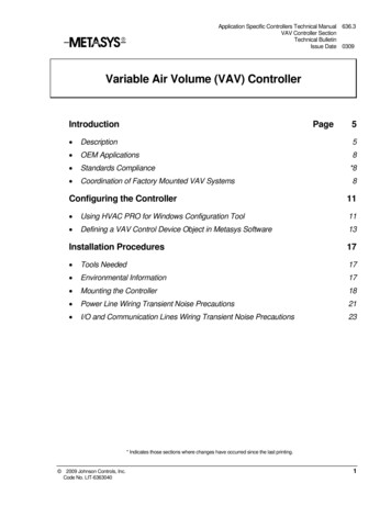
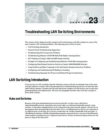
Cabling Your Cluster Hardware2Cabling the Mouse, Keyboard, and MonitorWhen installing a cluster configuration in a rack, you must include a switchbox to connect the mouse, keyboard, and monitor to the nodes. See thedocumentation included with your rack for instructions on cablingconnections of each node to the switch box.Cabling the Power SuppliesSee the documentation for each component in your cluster solution andensure that the specific power requirements are satisfied.The following guidelines are recommended to protect your cluster solutionfrom power-related failures: For nodes with multiple power supplies, plug each power supply into aseparate AC circuit. Use uninterruptible power supplies (UPS). For some environments, consider having backup generators and powerfrom separate electrical substations.Figure 2-1 illustrates recommended methods for power cabling for a clustersolution consisting of two Dell PowerEdge systems and a dual controller DellCompellent Storage Center. To ensure redundancy, the primary powersupplies of all the components are grouped into one or two circuits and theredundant power supplies are grouped into a different circuit.Cabling Your Cluster Hardware11
Figure 2-1. Power Cabling Example With Two Power Supplies in PowerEdge Systemscluster node 1cluster node 2CompellentStorageCenter controller 2CompellentStorageCenter controller 1primary power supplies on oneAC power strip [or one AC PDU(not shown)]redundant power supplies onone AC power strip [(or one ACPDU not shown)]Cabling Your Cluster for Public and PrivateNetworksThe network adapters in the cluster nodes provide at least two networkconnections for each node. See Table 2-1.Table 2-1. Network ConnectionsNetwork ConnectionDescriptionPublic networkAll connections to the client LAN.At least one public network must be configured for Mixedmode for private network failover.Private network12A dedicated connection for sharing cluster health andstatus information only.Cabling Your Cluster Hardware
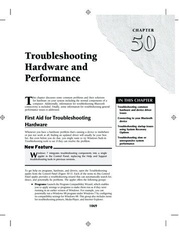
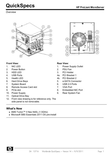
Figure 2-2 shows an example of cabling in which dedicated network adaptersin each node are connected to each other (for the private network) and theremaining network adapters are connected to the public network.Figure 2-2.Example of Network Cabling Connectionpublic networkpublicnetworkadapterprivate networkadapterprivate networkcluster node 1cluster node 2Cabling the Public NetworkAny network adapter supported by a system running TCP/IP may be used toconnect to the public network segments. You can install additional networkadapters to support additional public network segments or to provideredundancy in the event of a faulty primary network adapter or switch port.Cabling the Private NetworkThe private network connection to the nodes is provided by a differentnetwork adapter in each node. This network is used for intra-clustercommunications. Table 2-2 describes three possible private networkconfigurations.Cabling Your Cluster Hardware13
Table 2-2. Private Network Hardware Components and ConnectionsMethodHardware ComponentsConnectionNetworkswitchGigabit or 10 GigabitDepending on the hardware, connectEthernet network adapters the CAT5e or CAT6 cables, the multiand switchesmode optical cables with LocalConnectors (LCs), or the twinaxcables from the network adapters inthe nodes to a switch.Point-to-Point Copper Gigabit or 10Connect a standard CAT5e or CAT6GigabitEthernetnetworkEthernet cable between the network(two-nodeadapters in both nodes.clusters only) adapters with RJ-45connectorsCopper 10 GigabitConnect a twinax cable between theEthernet network adapters network adapters in both nodes.with SFP connectorsOptical Gigabit or 10Connect a multi-mode optical cableGigabit Ethernet network between the network adapters in bothadapters with LCnodes.connectorsNOTE: Throughout this document, Gigabit Ethernet is used to refer to either GigabitEthernet or 10 Gigabit Ethernet.Using Dual-Port Network AdaptersYou can configure your cluster to use the public network as a failover forprivate network communications. If you are using dual-port network adapters,do not configure both ports simultaneously to support both public andprivate networks.NIC TeamingNIC teaming combines two or more NICs to provide load balancing and faulttolerance. Your cluster supports NIC teaming, only in a public network. NICteaming is not supported in a private network.NOTE: Use the same brand of NICs in a team. Do not mix brands in NIC teaming.14Cabling Your Cluster Hardware
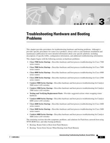
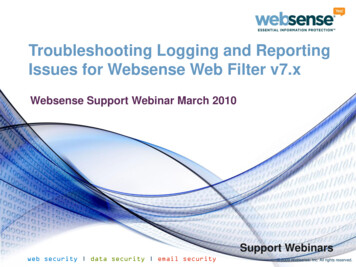
Cabling the Storage SystemThis section provides information on cabling your cluster to a storage systemin a SAN-attached configuration.Cabling a Cluster to a Compellent Storage Center Storage SystemA SAN-attached cluster is a cluster configuration where all cluster nodes thatare attached to the storage system through SAN use a redundant switchfabric.SAN-attached cluster configurations provide flexibility, expandability, andperformance.For more information on Fibre Channel switch fabrics, see "ImplementingZoning on a Fibre Channel Switched Fabric" on page 28.Figure 2-3 shows an example of a two node SAN-attached cluster.Figure 2-4 shows an example of an sixteen-node SAN-attached cluster.Similar cabling concepts can be applied to clusters with different number ofnodes.NOTE: The connections listed in this section are representative of one provenmethod of ensuring redundancy in the connections between the cluster nodes andthe storage system. Other methods that achieve the same type of redundantconnectivity may be acceptable.Cabling Your Cluster Hardware15
Figure 2-3.Two-Node SAN-Attached Clusterpublic networkcluster nodeprivate networkFibre ChannelconnectionsFibre ChannelconnectionsFibre ChannelswitchFibre Channelswitchstorage system16cluster nodeCabling Your Cluster Hardware
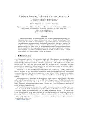
Figure 2-4.Sixteen-Node SAN-Attached Clusterpublic networkprivatenetworkcluster nodes (2-16)Fibre ChannelswitchFibre Channelswitchstorage systemCabling Your Cluster Hardware17
Cabling the Compellent Storage Center Back-EndFor information on how to cable the Compellent Storage Center back-end,see the Compellent Storage Center documentation. The following are twoexamples on how to connect the back-end cables.Figure 2-5.Back-End Cabling With One SAS ChainStorage CenterController 1Storage CenterController 2Storage Center SAS Storage EnclosuresI/O Cards18Cabling Your Cluster Hardware
Figure 2-6.Back-End Cabling With Multiple SAS ChainsStorage CenterController 1Storage CenterController 2Storage Center SAS Storage EnclosuresI/O CardsCabling the Cluster Nodes and the Compellent Storage Center Front-EndThe cluster nodes attach to the storage system using a redundant switchfabric and Fibre optic cables with duplex LC multimode connectors.The switches, the HBA ports in the cluster nodes, and the storage controllerports in the storage system use duplex LC multimode connectors. Theconnectors consist of two individual fibre optic connectors with indexed tabsthat must be inserted and aligned properly in the small form-factor pluggable(SFP) module connectors on the Fibre Channel switches and the connectorson the cluster nodes and storage systems.Cabling Your Cluster Hardware19
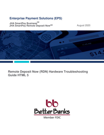
Each HBA port is cabled to a port on a Fibre Channel switch. One or morecables connect from the outgoing ports on a switch to a storage controller ona Compellent storage system.1 Connect cluster node 1 to the SAN:abConnect a cable from HBA port 0 to Fibre Channel switch 0 (sw0).Connect a cable from HBA port 1 to Fibre Channel switch 1 (sw1).2 Repeat step 1 for each additional cluster node.3 Connect the storage system to the SAN:Connect a cable from Fibre Channel switch 0 (sw0) to the first frontend fibre channel port on the Storage Center Controller 1.b Connect a cable from Fibre Channel switch 0 (sw0) to the first frontend fibre channel port on the Storage Center Controller 2.c Connect a cable from Fibre Channel switch 1 (sw1) to the secondfront-end fibre channel port on the Storage Center Controller 1.d Connect a cable from Fibre Channel switch 1 (sw1) to the secondfront-end fibre channel port on the Storage Center Controller 2.Add more cables to support port failover and provide more bandwidth:a20eConnect a cable from Fibre Channel switch 0 (sw0) to the third frontend fibre channel port on the Storage Center Controller 1.fConnect a cable from Fibre Channel switch 0 (sw0) to the third frontend fibre channel port on the Storage Center Controller 2.gConnect a cable from Fibre Channel switch 1 (sw1) to the fourthfront-end fibre channel port on the Storage Center Controller 1.hConnect a cable from Fibre Channel switch 1 (sw1) to the fourthfront-end fibre channel port on the Storage Center Controller 2.Cabling Your Cluster Hardware
Figure 2-7.Cabling a SAN-Attached Cluster to the Compellent Storage SystemCluster Node 2Cluster Node 1FibreChannelSwitch 0(sw0)Domain 1Domain 1Domain 1Domain 1Storage CenterController 1Domain 2Domain 2Domain 2Domain 2FibreChannelSwitch 1(sw1)Storage CenterController 2NOTE: Additional cables can be connected from the fibre channel switches to thestorage system if there are available front-end fibre channel ports on the storageprocessors.Cabling Multiple SAN-Attached Clusters to a Compellent Storage SystemTo cable multiple clusters to the storage system, connect the cluster nodes tothe appropriate Fibre Channel switches and then connect the Fibre Channelswitches to the appropriate the storage controllers.Cabling Multiple SAN-Attached Clusters to the Compellent Storage System1 In the first cluster, connect cluster node 1 to the SAN:aConnect a cable from HBA port 0 to Fibre Channel switch 0 (sw0).bConnect a cable from HBA port 1 to Fibre Channel switch 1 (sw1).2 In the first cluster, repeat step 1 for each additional cluster node.Cabling Your Cluster Hardware21
3 For each additional cluster, repeat step 1 and step 2.4 Connect the storage system to the SAN:aConnect a cable from Fibre Channel switch 0 (sw0) to the first frontend fibre channel port on the Storage Center Controller 1.bConnect a cable from Fibre Channel switch 0 (sw0) to the first frontend fibre channel port on the Storage Center Controller 2.cConnect a cable from Fibre Channel switch 1 (sw1) to the secondfront-end fibre channel port on the Storage Center Controller 1.dConnect a cable from Fibre Channel switch 1 (sw1) to the secondfront-end fibre channel port on the Storage Center Controller 2.Add more cables to support port failover and provide more bandwidth:eConnect a cable from Fibre Channel switch 0 (sw0) to the third frontend fibre channel port on the Storage Center Controller 1.fConnect a cable from Fibre Channel switch 0 (sw0) to the third frontend fibre channel port on the Storage Center Controller 2.gConnect a cable from Fibre Channel switch 1 (sw1) to the fourthfront-end fibre channel port on the Storage Center Controller 1.hConnect a cable from Fibre Channel switch 1 (sw1) to the fourthfront-end fibre channel port on the Storage Center Controller 2.Connecting a PowerEdge Cluster to a Tape LibraryTo provide additional backup for your cluster, you can add tape backup devicesto your cluster configuration. The Dell PowerVault tape libraries may containan integrated Fibre Channel bridge or Storage Network Controller (SNC) thatconnects directly to your Fibre Channel switch.Figure 2-8 shows a supported Failover Cluster configuration using redundantFibre Channel switches and a tape library. In this configuration, each of thecluster nodes can access the tape library to provide backup for your local diskresources, as well as your cluster disk resources. This configuration allows youto add more servers and storage systems in the future, if needed.NOTE: While tape libraries can be connected to multiple fabrics, they do notprovide path failover.22Cabling Your Cluster Hardware
Figure 2-8.Cabling a Storage System and a Tape Librarycluster nodecluster nodeprivate networkFibre ChannelswitchFibre Channelswitchtape librarystorage systemObtaining More InformationSee the storage and tape backup documentation for more information onconfiguring these components.Configuring Your Cluster With SAN BackupYou can provide centralized backup for your clusters by sharing your SANwith multiple clusters, storage systems, and a tape library.Figure 2-9 provides an example of cabling the cluster nodes to your storagesystems and SAN backup with a tape library.Cabling Your Cluster Hardware23
Figure 2-9.Cluster Configuration Using SAN-Based Backupcluster 1cluster 2FibreChannelswitchFibreChannelswitchstorage systemtape library24Cabling Your Cluster Hardware
Preparing Your Systems forClustering3WARNING: Only trained service technicians are authorized to remove andaccess any of the components inside the system. See your safety information forcomplete information about safety precautions, working inside the computer, andprotecting against electrostatic discharge.Cluster Configuration Overview1 Ensure that your site can handle the cluster’s power requirements.Contact your sales representative for information about your region'spower requirements.2 Install the systems, the shared storage array(s), and the interconnectswitches (for example, in an equipment rack), and ensure that all thecomponents are turned on.NOTE: For more information on step 3 through step 7 and step 10 throughstep 13, see the "Preparing your systems for clustering" section of Dell FailoverClusters with Microsoft Windows Server 2008 Installation andTroubleshooting Guide at support.dell.com/manuals.3 Deploy the operating system (including any relevant service packs andhotfixes), network adapter drivers, and storage adapter drivers (includingMultipath I/O (MPIO) drivers) on each cluster node. Depending on thedeployment method that is used, it may be necessary to provide a networkconnection to successfully complete this step.NOTE: To help in planning and deployment of your cluster, record the relevantcluster configuration information in the Cluster Data Form (see "Cluster DataForm" on page 45), and the Zoning configuration information in the ZoningConfiguration form (see "Zoning Configuration Form" on page 43).4 Establish the physical network topology and the TCP/IP settings fornetwork adapters on each cluster node to provide access to the clusterpublic and private networks.Preparing Your Systems for Clustering25
5 Configure each cluster node as a member in the same Microsoft WindowsActive Directory Domain.NOTE: You can configure the cluster nodes as Domain Controllers. For moreinformation, see the “Selecting a Domain Model” section of Dell FailoverClusters with Microsoft Windows Server 2008 Installation andTroubleshooting Guide at support.dell.com/manuals.6 Establish the physical storage topology and any required storage networksettings to provide connectivity between the storage array and the systemsthat you are configuring as cluster nodes. Configure the storage system(s)as described in your storage system documentation.7 Use storage array management tools to create at least one logical unitnumber (LUN). The LUN is used as a Witness disk for Windows Server2008 Failover cluster. Ensure that this LUN is presented to the systemsthat you are configuring as cluster nodes.NOTE: For security reasons, it is recommended that you configure the LUN ona single node as mentioned in step 8 when you are setting up the cluster.Later, you can configure the LUN as mentioned in step 9 so that other nodes inthe cluster can access it.8 Select one of the systems and form a new failover cluster by configuringthe cluster name, cluster management IP, and quorum resource. See"Preparing Your Systems for Clustering" on page 25.NOTE: For Failover Clusters configured with Windows Server 2008, run theCluster Validation Wizard to ensure that your system is ready to form thecluster.9 Join the remaining node(s) to the failover cluster. See "Preparing YourSystems for Clustering" on page 25.10 Configure roles for cluster networks.11 Test the failover capabilities of your new cluster.NOTE: For Failover Clusters configured with Windows Server 2008, you canalso use the Cluster Validation Wizard.12 Configure highly-available applications and services on your FailoverCluster. Depending on your configuration, this may also require providingadditional LUNs to the cluster or creating new cluster resource groups.Test the failover capabilities of the new resources.26Preparing Your Systems for Clustering
13 Configure client systems to access the highly-available applications andservices that are hosted on your failover cluster.Installation OverviewEach node in your Dell Failover Cluster must be installed with the samerelease, edition, service pack, and processor architecture of the WindowsServer operating system. For example, all nodes in your cluster may beconfigured with Windows Server 2008 R2, Enterprise x64 Edition. If theoperating system varies among nodes, it is not possible to configure a FailoverCluster successfully. It is recommended that you establish server roles prior toconfiguring a Failover Cluster, depending on the operating system configuredon your cluster.For a list of Dell PowerEdge Servers, Fibre Channel HBAs, and switches, andrecommended list of operating system variants, specific driver and firmwarerevisions, see the Dell Cluster Configuration Support Matrices at dell.com/ha.For more information on deploying your cluster with Windows Server 2008operating systems, see the Dell Failover Clusters with Microsoft WindowsServer 2008 Installation and Troubleshooting Guide atsupport.dell.com/manuals.The following sub-sections describe the procedure to enable communicationbetween the cluster nodes and your shared Dell Compellent storage array, andto present disks from the storage array to the cluster.Installing the Fibre Channel HBAsFor dual-HBA configurations, it is recommended that you install the FibreChannel HBAs on separate peripheral component interconnect (PCI) buses.Placing the adapters on separate buses improves availability and performance.For more information about your system's PCI bus configuration andsupported HBAs, see the Dell Cluster Configuration Support Matrices atdell.com/ha.Preparing Your Systems fo
mode for private network failover. Private network A dedicated connection for sharing cluster health and status information only. Compellent Storage Center - controller 1 Compellent Storage Center - controller 2 primary power supplies on one AC power strip [or one AC PDU (not shown)] cluster node 1 cluster node 2 redundant power supplies on