Transcription
USE & CARE GUIDE612,000-14,000 BTUThrough The Wall Heat-Cool A/C UnitCTWMHE12B2 CTWMHE14B2Customer Focused. Quality Driven.TMwww.crosley.com
TABLE OF CONTENTSImportant Safety Instructions .1-3Installation Instructions . 4-17Normal Sounds .18Air Conditioner Features .18-20Care and Cleaning .20-21Troubleshooting .21-22Before using your air conditioner, please readthis manual carefully and keep it for future reference.
IMPORTANT SAFETY INSTRUCTIONSREAD THIS MANUALInside you will find many helpful hints on how to use and maintain your air conditionerproperly. Just a little preventive care on your part can save you a great deal of timeand money over the life of your air conditioner. You'll find many answers to commonproblems in the chart of troubleshooting tips. If you review our chart of TroubleshootingTips first, you may not need to call for service at all.To prevent injury to the user or other people and property damage, the followinginstructions must be followed. Incorrect operation due to ignoring of instructions maycause harm or damage. The seriousness is classified by the following indications.WARNING This symbol indicates the possibility of death or serious injury.CAUTION This symbol indicates the possibility of injury or damage to property.Always do this.Never do this.WARNING!!!!!!Plug in power plugproperly.Do not operate or stop theunit by inserting or pullingout the power plug.Do not damage or use an unspecified powercord.Otherwise, it may cause electricshock or fire due to excess heatgeneration.It may cause electric shock or firedue to heat generation.It may cause electric shock or fire.If the power cord is damaged, it must be replaced by themanufacturer or an authorised service centre or a similarlyqualified per son in order to avoid a hazard.Always install circuitbreaker and a dedicatedpower circuit.Do not operate with wethands or in dampenvironment.Do not direct airflow at room occupants only.Incorrect installation may causefire and electric shock.It may cause electric shock.This could damage your health.Always ensure effectivegrounding.Do not allow water to runinto electric parts.!Incorrect grounding may causeelectric shock.It may cause failure of machineor electric shock.It may cause electric shock or fire due to heat generation.Unplug the unit if strangesounds, smell, or smokecomes from it.Do not use the socket if it isloose or damaged.It may cause fire and electricshock.It may cause fire and electricshock.Keep firearms away.Do not use the power cordclose to heating appliances.It may cause fire.It may cause fire and electricshock.Ventilate room before operating air conditioner if there isa gas leakage from another appliance.Do not modify power cord length or share theoutlet with other appliances.Do not open the unit during operation.It may cause electric shock.Do not use the power cord near flammable gasor combustibles, such as gasoline, benzene,thinner, etc.It may cause an explosion or fire.Do not disassemble or modify unit.It may cause failure and electric shock.It may cause explosion, fire and, burns.1
IMPORTANT SAFETY INSTRUCTIONSCAUTION!When the air filter is to beremoved, do not touch the metalparts of the unit.It may cause an injury.Do not put a pet or house plantwhere it will be exposed to directair flow.This could injure the pet or plant.Do not use strong detergentsuch as wax or thinner but usea soft cloth.Appearance may be deteriorateddue to change of product color orscratching of its surface.Do not clean the air conditionerwith water.Stop operation and close thewindow in storm or hurricane.Water may enter the unit anddegrade the insulation. It maycause an electric shock.!Operation with windows openedmay cause wetting of indoor andsoaking of household furniture.!Always insert the filters securely.Clean filter once every two weeks.Operation without filters maycausefailure.Do not place obstacles aroundair-inlets or inside of air-outlet.!!An oxygen shortage may occur.Do not use for special purposes.Do not use this air conditioner topreserve precision devices, food,pets, plants, and art objects.It maycause deterioration of quality, etc.When the unit is to be cleaned,switch off, and turn off the circuitbreaker.Do not clean unit when power is onas it may cause fire and electric shock,it may cause an injury.!!Hold the plug by the head of thepower plug when taking it out.!It may cause electric shock anddamage.Do not place heavy object on the powercord and ensure that the cord is notcompressed.Ventilate the room well whenused together with a stove, etc.Ensure that the installation bracket of theoutdoor appliance is not damaged dueto prolonged exposure.If bracket is damaged, there isconcern of damage due to fallingof unit.Turn off the main powerswitch when not using theunit for a long time.It may cause failure of product orfire.Do not drink water drainedfrom air conditioner.It contains contaminants andIt may cause failure of applianceThere is danger of fire or electriccould make you sick.or accident.shock.! Use caution when unpacking and! If water enters the unit, turn the unit off at the poweroutlet and switch off the circuit breaker. Isolateinstalling. Sharp edges could cause injury.supply by taking the power-plug out and contact aqualified service technician.CAUTIONThe appliance shall be installed in accordancewith national wiring regulations.Do not operate your air conditioner in a wet roomsuch as a bathroom or laundry room.The appliance with electric heater shall have atleast 1 meter space to th e combustible materials.Contact the authorised service technician forrepair or maintenance of this unit.Contact the authorised installer for installationof this unit.This appliance is not intended for use by persons(including children) with reduced physical ,sensoryor mental capabilities or lack of experience andknowledge, unless they haveb eengi vensu pervisionor instruction concerning use of the appliance bya person responsible for their safety.Children should be supervised to ensure that theydo not play with the appliance.If the supply cord is damaged, it must be replacedby the manufacturer, its service agent or similarlyqualified persons in order to avoid a hazard.2
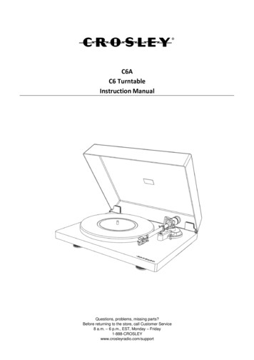
IMPORTANT SAFETY INSTRUCTIONSWARNINGNOTE:The power supply cord with this airconditioner contains a current detectiondevice designed to reduce the risk of fire.Please refer to the section Operationof Current Device for details.In the eventthat the power supply cord is damaged,it cannot be repaired-it must be replacedwith ac ordf romt heP roductM anufacturer.WARNINGAvoid fire hazard or electric shock. Do notuse an extension cord or an adaptor plug.Do not remove any prong from the powercord.Grounding type wallreceptacleDo not, under anycircumstances, cut,remove, or bypassthe grounding prong.Power supply cordwith 3-prong grounding plugand current detection deviceFor Your SafetyDo not store or use gasoline or other flammable vapors and liquids in the vicinityof this or any other appliance.WARNINGPrevent AccidentsTo reduce the risk of fire, electrical shock, or injury to persons when using yourair conditioner, follow basic precautions, including the following:Be sure the electrical service is adequate for the model you have chosen. Thisinformation can be found on the serial plate, which is located on the side of thethe cabinet and behind the grille.If the air conditioneri s to be installed in a w indow, you will probably want to cleanboth sides of the glass first.I f the windowis a triple-track type with a screen panelincluded, remove the screen completely before installation.Be sure the air conditionerh as been securely and correctly installed according tothe installation instructions in this manual. Save this manual for possible futureuse in removing or installing this unit.When handling the air conditioner, be careful to avoid cuts f rom sharp metal f inson front and rear coils.WARNINGElectrical InformationThe complete electical rating of your new room air conditioner is stated on theserial plate. Refer to the rating when checking the electrical requirements.Be sure the air conditioner is properly grounded. To minimize shock and firehazards, proper grounding is important. The power cord is equipped with athree-prong grounding plug for protection against shock hazards.Your air conditioner must be used in a properly grounded wall receptacle. If thewall receptacle you intend to use is not adequately grounded or protected by atime delay fuse or circuit breaker, have a qualified electrician install the properreceptacle. Ensure the receptacle is accessible after the unit installation.Do not run air conditioner without side protective cover in place.This couldresult in mechanical damage within the air conditioner.Do not use an extension cord or an adapter plug.Operation of Current DeviceNOTE:(Applicable to the unit adopts current detectiondevice only )The power supply cord contains a current device that sensesdamage to the power cord. To test your power supply cord dothe following:1. Plug in the Air Conditioner.2. The power supply cord will have TWO buttons on the plughead. Press the TEST button, you will notice a click as theRESET button pops out.3. Press the RESET button, again you will notice a click asthe button engages.4. The power supply cord is now supplying electricity to theunit. (On some products this it also indicated by a light onthe plug head.)Do not use this device to turn the unit on or off.Always make sure the RESET button is pushed in forcorrect operation.The power supply must be replaced if it fails reset wheneither the TEST button is pushed, or it cannot be reset. Anew one can be obtained from the product manufacturer.If power supply cord is damaged, it cannot be repaired. ItMUST be replaced by one obtained from the productmanufacturer.NOTE:This air conditioner is designed to be operatedunder condition as follows:Cooling Outdoor temp:operation Indoor temp:64-109OF/18-43OC (64-125OF/18-52OCfor special tropical models)OO62-90 F/17-32 C23-76OF/-5-24 CHeating Outdoor temp:Ooperation Indoor temp:32-80 F/0-27 CNote: Performance may be reduced outside of theseoperating temperatures.OO3
INSTALLATION INSTRUCTIONSDo This First (for existing sleeve)BEFORE YOU BEGINNote that the air conditioner dimensions are: 24 incheswide, 14 inches high, and 18 inches deep(without front).Install Air Conditioner according to these installationinstructions to achieve the best performance. Savethese installation instructions for future reference.NOTE: Do not use any screws other than thosespecified here.Read these instructions completelyand carefully.IMPORTANT- Save theseinstructions for local inspector s use.IMPORTANT- Observe allgoverning codes and ordianaces.Note to Installer- Be sure to leave theseinstructions with the Consumer.Note to Consumer- Keep theseinstructions for futrue reference.Skill level- Installatio of this appliancerequires basic mechanical skills.Completion time- Approximately 1 hour.We recommend that two people installthis product.Proper installation is the responsibilityof the installer.Product failure due to improper installationis not covered under the Warranty.You MUST use all supplied parts and useproper installation procedures as describedin these instructions when installing this airconditioner.Items in KitYou may not need all parts in the kit. Discard unusedparts.NameSpec.Qty2Tapered Spacer Blocks17 Long111Centering/Support Blocks4 /2 x3 /2 x 1 /24Plastic Divider1/8 x41/2 x141/2 2Stuffer Seal11 x11/2 x84Seal1 x11/2 x2531Seal21 x1 /2 x14Seal1 x3/8 x253Seal21 x3/8 x14Seal21 x3/4 x14CAUTIONDo not, under any circumstances, cut or remove thethird (ground) prong from the power cord.Do not change the plug on the power cord of the airconditioner.Aluminum house wiring may present specialproblems- consult a qualified electircian.When handling unit, be careful to avoid cuts from sharpmetal edges and aluminum fins on front and rear coils.Trim Frame(side legs)Trim Frame(top & bottom legs)Ground Wire(green)Toothed Washer for groundingscrew22Grounding ScrewGrille(plastic)Grille AluminumNuts(plastic)Screw WasherScrew11144412NOTE:Save Carton and these Installation Instructions for futurereference. The carton is the best way to store unit duringwinter, or when not in use.4
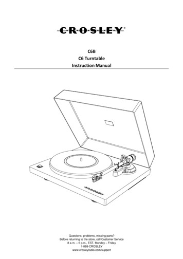
INSTALLATION INSTRUCTIONSHow to Install1. Identify the wall-sleeve brand for your installation, from the chart below.BrandWall Sleeve se251/2151/416,171/2 or 22FrigidaireCarrier(52F Series)26155/815 7/8General Electric/HotpointWhirlpool257/8161/217 1/8 or 233/Fedders/Emerson2716 416 3/4 or 193/4Sears/Kenmore253/4167/818 5/8Carrier(51S 16 3/4NOTE: All wall sleeves used to mount the new Air Conditioner must be in sound structural conditionand have a rear grille that securely attaches to sleeve, or rear flange that serves as a stop for the AirConditioner.15/4CAUTION: When installation is complete,replacement unit MUST have a rearwardslope as shown.to /16WallSleeveU N ITFRONTREARLEVEL2. Remove old Air Conditioner from wall sleeve and prepare wall sleeve as follows:--- Clean interior (do not disturb seals).--- Wall sleeve must be securely fastened in wall before installing Air Conditioner.Drive more nails or screws through sleeve, into wall, if needed.3--- Repair paint if needed.Max.3. If not existing, drill a 1/8 clearance hole forgrounding screw through left side of wall sleeve,Wall sleeve to unitin a clear area about 3 inches maximum back from sleeve groundingfront edge of sleeve, using grounding screw andtoothed washer. Pull loose end of ground wire out1front of sleeve, and temporarily bend it down andaround lower edge of sleeve.This ground wire willlater be attached to frame of air conditioner onceit is installed.1/8Hole4. Prepare the wall sleeve for installation of the new unit per the following Brand instructions.#1 Emerson15 Deep#2 Fedders193/4 Deep#3 Fedders or Friedrich16 3/4 Deep#4 General Electric/Hotpoint16 7/8 Deep#5 Sears or Carrier(51S Series)185/8 Deep#6 Whirlpool17 1/8 Deep#7 Whirlpool23 Deep#8 White-Westinghouse/16 17 1/2 DeepFrigidaire/Carrier(52F Series)#9 White-Westinghouse/Frigidaire22 Deep5. Identify your wall sleeve type and follow the instructions for that type in the following pages.5
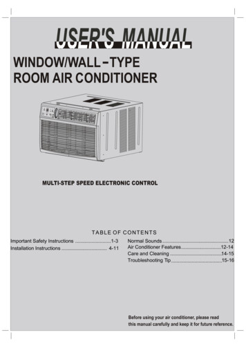
INSTALLATION INSTRUCTIONSIMPORTANTThis units increased performance characteristics result from having two rear air intakes.It is very important that these installation instructions are followed so your unit can operate atmaximum efficiency.If this is an existing sleeve, and there is an existing rear grille, it needs to be replaced by one thathas been shipped with the unit in the accessory kit.FOR INCREASED EFFICIENCY,UTILIZE THE PROVIDED LOUVERED REAR PANELInstallation of new grille provided with unit1. Remove the existing grille.2. Place the grille included with the new air conditioner towards the rear of the sleeve.3. Mark through the hole positions.4. Drill through the sleeves flanges with a 1/8 drill bit.5. Attached the new grille with self-threading screws and washers.6. It is VERY IMPORTANT that the grill e is placed exactly as shown below.7.Most decorative exterior grilles may be left in place as long as the proper interior air direction grilleis installed.6
INSTALLATION INSTRUCTIONSWall Sleeve Brands:#1 Emerson438 8315 Deep1. Remove existing rear grille as shown on Page6 of this manual and replace with providedlouvered rear panel. Install as shown here.4NOTE: You may need to drill holes in flange ofexisting sleeve to match new rear grille.42. Attach(1)1 x3/8 x25 long seal in the center atthe top of the sleeve. Remove the backing paperand press into position.3. Attach the (2) 1 x3/8 x14 long seals to theleft and right sides of the sleeve.4. Cut (2) 1 x3/8 x25 long seals to 14 long,andattach it to the vertical sections of the rear grilleas shown.5. Attach (2)41/2 x3 1/2 x11/2 centering/support blocksone on each side wall. Place in center of sidewall with the tapered end facing the opening.6. Gently slide unit into sleeve.7. Before sliding all-the-way back, remove 2ndscrew from front on left side of unit.8. Remove the plastic washer from the screw.9. Screw and attach the other end of the groundwire to the unit as shown in picture. Make surethat the toothed washer is against the cabinet.10.Slide the unit completely to the rear to ensurea good seal, making sure the ground wire doesnot become tangled.11.Seal & Frame the unit as described on page 17.12. If you have difficulty with mounting the grill tothe sleeve, follow the instructions for directmounting on Page 16.427
INSTALLATION INSTRUCTIONSWall Sleeve Brands:193/4 Deep#2 Fedders438 831. Remove existing rear grille as shown on Page6 of this manual and replace with providedlouvered rear panel. Install as shown here.4NOTE: You may need to drill holes in flangeof existing sleeve to match new rear grille.2. Attach(2)41/2 x31/2 x11/2 centering/support blocksone on each side wall. Place in center of sidewall with the tapered end facing the opening.3. Cut (2) 17 Tapered Spacer Blocks as shownbelow into two pieces.541743/4Tapered Spacer Block14Cut HereProtection PaperBacking4. The 4 section is placed in front of the rib onbase with the tapered end facing the back ofthe sleeve. The remaining portion will beplaced behind the rib again sloping towardthe rear of the sleeve. This helps induce arearward slope on the unit.5. Attach (1)1 x3/8 x25 long seal in the centerat the top of the sleeve. Remove the backingpaper and press into position.6. Attach (2) 1 x3/8 x14 seals to the left andright sides of the sleeve.7. Cut (2) 1 x3/8 x25 long seals to 14 longand attach it to the vertical sections of the reargrille as shown.8. Gently slide unit into sleeve.9. Before sliding all-the-way back, remove 2ndscrew from front on left side of unit.10. Remove the plastic washer from the screw.11. Screw and attach the other end of the groundwire to the unit as shown in picture. Make surethat the toothed washer is against the cabinet.12.Slide the unit completely to the rear to ensurea good seal, making sure the ground wire doesnot become tangled.13.Seal & Frame the unit as described on page 17.14. If you have difficulty with mounting the grill tothe sleeve, follow the instructions for directmounting on Page 16.8
INSTALLATION INSTRUCTIONSWall Sleeve Brands:163/4 Deep#3 Fedders or Friedrich438 831.Remove existing rear grille as shown on Page6 of this manual and replace with providedlouvered rear panel. Install as shown here.4NOTE: You may need to drill holes in flange ofexisting sleeve to match new rear grille.2. Attach(2)41/2 x31/2 x11/2 centering/support blocksone on each side wall. Place in center of sidewall with the tapered end facing the opening.3. Cut (2) 17 Tapered Spacer Blocks as shownbelow into three pieces.541743/4Cut HereTapered Spacer Block12-1/212-1/2 Protection PaperBacking4. The 2 1/2 section is placed in front of the rib onbase with the tapered end facing the back ofthe sleeve. Cut the remaining portion to 12 1/2and placed behind the rib again sloping towardthe rear of the sleeve. This helps induce arearward slope on the unit.5. Attach (1)1 x3/8 x25 long seal in the centerat the top of the sleeve. Remove the backingpaper and press into position.6. Attach (2) 1 x3/8 x14 seals to the left andright sides of the sleeve.7. Cut (2) 1 x3/8 x25 long seals to 14 longand attach it to the vertical sections of the reargrille as shown.8. Gently slide unit into sleeve.9. Before sliding all-the-way back, remove 2ndscrew from front on left side of unit.10. Remove the plastic washer from the screw.11. Screw and attach the other end of the groundwire to the unit as shown in picture. Make surethat the toothed washer is against the cabinet.12.Slide the unit completely to the rear to ensurea good seal, making sure the ground wire doesnot become tangled.13.Seal & Frame the unit as described on page 17.14. If you have difficulty with mounting the grill tothe sleeve, follow the instructions for directmounting on Page 16.9
INSTALLATION INSTRUCTIONSWall Sleeve Brands:#4 General Electra/Hotpoint 167/8 Deep438 81. Remove existing rear grille as shown on Page6 of this manual and replace with providedlouvered rear panel. Install as shown here.43NOTE: You may need to drill holes in flange ofexisting sleeve to match new rear grille.2. Cut (2) 17 Tapered Spacer Blocks as shownbelow into two pieces.1744543/4Tapered Spacer Block131Cut HereProtection PaperBacking3. Install 13 section as shown with the tapered end1/2 from the back of the sleeve. This helps induce arearward slop on the unit.4. Attach (1)1 x3/8 x25 long seal in the centerat the top of the sleeve. Remove the backingpaper and press into position.5. Attach (2) 1 x3/8 x14 seals to the left andright sides of the sleeve.6. Cut (2) 1 x3/8 x25 long seals to 14 longand attach it to the vertical sections of the reargrille as shown.7. Center unit and gently slide unit into sleeve.8. Before sliding all-the-way back, remove 2ndscrew from front on left side of unit.9. Remove the plastic washer from the screw.10. Screw and attach the other end of the groundwire to the unit as shown in picture. Make surethat the toothed washer is against the cabinet.11.Slide the unit completely to the rear to ensurea good seal, making sure the ground wire doesnot become tangled.12.Seal & Frame the unit as described on page 17.13. If you have difficulty with mounting the grill tothe sleeve, follow the instructions for directmounting on Page 16.10
INSTALLATION INSTRUCTIONSWall Sleeve Brands:#5 Sears or Carrier 51S Series( 185/8 Deep)438 8431. Remove existing rear grille as shown on Page6 of this manual and replace with providedlouvered rear panel. Install as shown here.NOTE: You may need to drill holes in flange ofexisting sleeve to match new rear grille.2. Install (2) tapered spacer blocks to the floor ofthe sleeve as shown. This helps induce arearward slop on the unit.4453. Install as shown with the tapered end 1/2 fromthe back of the sleeve. This helps induce arearward slop on the unit.4. Attach (1)1 x3/8 x25 long seal in the centerat the top of the sleeve. Remove the backingpaper and press into position.5. Attach (2) 1 x3/8 x14 seals to the left andright sides of the sleeve.6. Cut (2) 1 x3/8 x25 long seals to 14 longand attach it to the vertical sections of the reargrille as shown.7. Center unit and gently slide unit into sleeve.8. Before sliding all-the-way back, remove 2ndscrew from front on left side of unit.9. Remove the plastic washer from the screw.10. Screw and attach the other end of the groundwire to the unit as shown in picture. Make surethat the toothed washer is against the cabinet.11.Slide the unit completely to the rear to ensurea good seal, making sure the ground wire doesnot become tangled.12.Seal & Frame the unit as described on page 17.13. If you have difficulty with mounting the grill tothe sleeve, follow the instructions for directmounting on Page 16.411
INSTALLATION INSTRUCTIONSWall Sleeve Brands:#6 Whirlpool438 81. Remove existing rear grille as shown on Page6 of this manual and replace with providedlouvered rear panel. Install as shown here.43171/8 DeepNOTE: You may need to drill holes in flange ofexisting sleeve to match new rear grille.2. Cut (2) 17 Tapered Spacer Blocks as shownbelow into two pieces.174453/44Tapered Spacer Block113Cut HereProtection PaperBacking3. Install 13 section to the floor of the sleeve asshown. This helps induce a rearward slop on theunit.4. Attach (1)1 x3/8 x25 long seal in the centerat the top of the sleeve. Remove the backingpaper and press into position.5. Attach (2) 1 x3/8 x14 seals to the left andright sides of the sleeve.6. Cut (2) 1 x3/8 x25 long seals to 14 longand attach it to the vertical sections of the reargrille as shown.7. Center unit and gently slide unit into sleeve.8. Before sliding all-the-way back, remove 2ndscrew from front on left side of unit.9. Remove the plastic washer from the screw.10. Screw and attach the other end of the groundwire to the unit as shown in picture. Make surethat the toothed washer is against the cabinet.11.Slide the unit completely to the rear to ensurea good seal, making sure the ground wire doesnot become tangled.12.Seal & Frame the unit as described on page 17.13. If you have difficulty with mounting the grill tothe sleeve, follow the instructions for directmounting on Page 16.12
INSTALLATION INSTRUCTIONSWall Sleeve Brands:#7 Whirlpool43458 831. Remove existing rear grille as shown on Page6 of this manual and replace with providedlouvered rear panel. Install as shown here.4NOTE: You may need to drill holes in flange ofexisting sleeve to match new rear grille.Because of the increased unit depth, first trydry fitting using the method described below:2. Place (2) 1 x11/2 x14 seals against each side.3. Gently slide unit in and check if amount extending from the sleeve is sufficient once the trimframe is attached.4. If position is Ok, remove unit and proceed tothe next step. If not go to step 9.5. Attach (1)1 x11/2 x25 long seal in the centerat the top of the sleeve. Remove the backingpaper and press into position.6. Attach (2) 1 x11/2 x14 seals to the left andright sides of the sleeve.7. Cut (2) 1 x 3/8 x25 long seals to 14 longand attach to the vertical sections of the grille asshown.8. Attach the tapered spacer blocks to the floor ofthe sleeve. Now go to step 15.4677141049( 23 Deep)Use these next steps if the unit requires extraextension into the room.9. Attach 1 x3/4 x14 long seal over the solidvertical portion of the rear grille.10. Attach (4) 41/2 x31/2 x11/2 foam blocks with theslot overlapping the seal above.11. Install the divider into the slots of the foamblocks. You may need to trim the length to size.12. Repeat steps 9-11 for the other vertical shownportion of the grille as shown in the picture.13. Attach (2) 1 x11/2 x14 seals along the sidesof the sleeve again making sure all seals areflush.14.Cut the 1 x11/2 x25 seal to fit the top of thesleeve. The pieces must be fitted flush to theedge of the divider.15. Center unit and gently slide unit into sleeve.16. Before sliding all-the-way back, remove 1stscrew from front on left side of unit.17. Remove the plastic washer from the screw.18. Screw and attach the other end of the groundwire to the unit as shown in picture. Make surethat the toothed washer is against the cabinet.19.Slide the unit completely to the rear to ensurea good seal, making sure the ground wire doesnot become tangled.20.Seal & Frame the unit as described on page 17.21. If you have difficulty with mounting the grill tothe sleeve, follow the instructions for directmounting on Page 16.412131113
INSTALLATION INSTRUCTIONSWall Sleeve Brands:438 83#8 White Westinghouse/Frigidaire/Carrier 52F Series ( 16 171/2 Deep)41.Remove existing rear grille as shown on Page6 of this manual and replace with providedlouvered rear panel. Install as shown here.NOTE: You may need to drill holes in flange ofexisting sleeve to match new rear grille.422. Attach (1)1 x3/8 x25 long seal in the centerat the top of the sleeve. Remove the backingpaper and press into position.3. Attach (2) 1 x3/8 x14 seals to the left andright sides of the sleeve.4. Attach (2) 1 x3/4 x14 long seals vertically 4.5from the left side of the sleeve .Attach the other1 x3/4 x14 long seal 4 from the right side of thesleeve.5. Center unit and gently slide unit into sleeve.6. Before sliding all-the-way back, remove 2ndscrew from front on left side of unit.7. Remove the plastic washer from the screw.8. Screw and attach the other end of the groundwire to the unit as shown in picture. Make surethat the toothed washer is against the cabinet.9. Slide the unit completely to the rear to ensurea good seal, making sure the ground wire doesnot become tangled.10.Seal & Frame the unit as described on page 17.11. If you have difficulty with mounting the grill tothe sleeve, follow the instructions for directmounting on Page 16.43414
INSTALLATION INSTRUCTIONSWall Sleeve Brands:#9 White Westinghouse or Frigidaire( 22 Deep)4348 81. Remove existing rear grille as shown on Page6 of this manual and replace with providedlouvered rear panel. Install as shown here.43NOTE: You may need to drill holes in flangeof existing sleeve to match new rear grille.Because of the increased unit depth, first trydry fitting using the method described below:2. Place (2) 1 x11/2 x14 seals against each side.3. Gently slide unit in and check if amount extending from the sleeve is sufficient once the trimframe is attached.4. If position is Ok, remove unit and proceed tothe next step. If not go to step 8.5. Attach (1)1 x11/2 x15 long seal to the left andright sides of the sleeve.6. Cut (1) 1 x11/2 x25 long seal to 14 long andattach it vertically to the rear grill 4.5 fromthe left side ,repeat and attach 4 from the rightside.7. Attach(1) 1 x11/2 x25 long seal in the center atthe top of the sleeve.Remove the backing paperand press into position.Proceed to step 14.Use these next steps if the unit requires extraextension into the room.8. Attach 1 x3/4 x14 long seal over the solidvertical portion of the rear grille.9. Attach (4) 41/2 x31/2 x11/2 foam blocks with theslot overlapping the seal above.10. Install the divider into the slots of the foamblocks. You may need to trim the length to size.11. Repeat steps 8-10 for the other vertical shownportion of the grille as shown in the picture.12. Attach (2) 1 x11/2 x14 seals along the sidesof the sleeve again making sure all seals areflush.13.Cut the 1 x11/2 x25 seal to fit the top of thesleeve. The pieces must be fitted flush to theedge of the divider.14. Center unit and gently slide unit into sleeve.15
the installation instructions in this manual. Save this manual for possible future use in removing or installing this unit. When handling the air conditioner, be careful to avoid cuts f ro m sharp metal f ins on front and rear coils. The complete electical rating of your new room air conditioner is stated on the serial plate.