Transcription
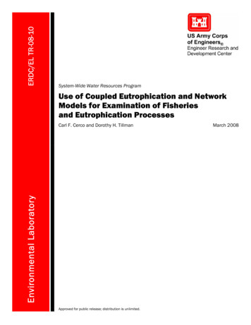
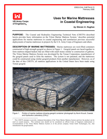
ERDC/CHL CHETN-III-72February 2006Uses for Marine Mattressesin Coastal Engineeringby Steven A. HughesPURPOSE: The Coastal and Hydraulics Engineering Technical Note (CHETN) describedherein provides basic information on the Triton Marine Mattress System, 1 describes potentialapplications for marine mattresses in coastal engineering and summarizes previous successfuldeployments of marine mattresses in projects by the U.S. Army Corps of Engineers and others.DESCRIPTION OF MARINE MATTRESSES: Marine mattresses are rock-filled containersconstructed of high-strength geogrid as shown in Figure 1. Geogrid panels are laced together toform mattress-shaped baskets that are filled with small stones similar to construction of gabions.The Triton Marine Mattress System was developed by the Tensar Corporation, manufacturer ofthe geogrid panels used to form the mattress. The system is not patented, and the mattressescould be constructed using similar geogrid products from another manufacturer. However, as ofthe date of this CHETN, all mattress applications in the United States have been made usingTensar geogrid.Figure 1.1Portion of marine mattress showing geogrid container (photograph by Kevin Knuuti, Coastaland Hydraulics Laboratory (CHL))This CHETN attempts to provide a balanced description of the Triton Marine Mattress System and how the product can beused on coastal projects. This technical note should not be considered an official Corps of Engineers endorsement orrecommendation of the Triton Marine Mattress System or of the private company Tensar Earth Technologies, Inc., thatmanufactures the geogrid panels.
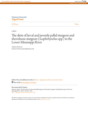
ERDC/CHL CHETN-III-72February 2006Typical width for a single marine mattress is about 5 ft, but this can vary according to placementplan and contractor capability. Mattress lengths vary up to a recommended maximum of 35 ft.Mattress thickness is usually between 8 and 12 in. for revetment applications, but thicknesses canvary between 4 in. for bedding layers up to 24 in. for heavy-duty applications exposed to wavesand currents. Assuming the stone fill has a volumetric weight of about 110 lb/cu ft, a 35-ft-long,5-ft-wide, 1-ft-thick mattress weighs approximately 9.6 tons. The high-strength geogrid hassufficient strength to permit rock-filled mattresses up to 35 ft in length to be hoisted from oneend for placement at the project site. However, keep in mind this guidance is for mattresses12 in. thick or less. Check with the geogrid manufacturer for maximum mattress lengthsassociated with mattresses thicker than 12 in. and widths of about 5 ft. Figure 2 shows a stack ofmarine mattresses prior to placement. Figure 3 shows lifting of a mattress from both ends. Thecellular construction of the mattress using internal diaphragms maintains the uniform thicknessof the stone fill material during the lifting and placement operations.Figure 2.Stack of filled marine mattresses staged for placement on National Shoreline Erosion ControlDevelopment and Demonstration Program (Section 227) project in Seabrook, NH(photograph by Kevin Knuuti, CHL)USES OF MARINE MATTRESSES IN COASTAL ENGINEERING: A marine mattress isa large, monolithic unit with porosity similar to placed riprap or some bedding layers. Severalapplications of marine mattresses in coastal projects (Olsen 2001) are described in the followingsections.Revetment Units for Low to Moderate Wave Exposure. A common application formarine mattresses is bank protection for rivers and shorelines of protected bays and lakes.Because of the geogrid container, the mattresses will tolerate more wave action than comparablerevetments made of significantly larger loose stone. When protecting sand or soil, appropriatefilter layers of gravel or geotextile filter cloth must be included in the cross-section design. Aprimary mattress failure mode under wave action is failure of the geogrid or the lacing that holdsthe panels together. If this occurs, the stones will no longer be confined, and the mattress could2
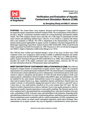
ERDC/CHL CHETN-III-72February 2006Figure 3.Installation of mattress at Barnegat Inlet, NJ (photograph courtesy of Tensar EarthTechnologies)start to unravel. For wave protection applications, stone movement within the mattress must beminimized to preclude interior wear of the mattress containment geogrid superstructure.Movement of an entire mattress unit by wave action is also a potential failure mode under severewave condition. Mattresses placed on steep slopes without adequate toe buttressing or tiebackanchors at the top could slide downslope as a unit, or the mattresses could fail by buckling ifwaves are powerful enough to lift portions of the mattress and the mattress is not properlycompartmentalized.Limited data exist on marine mattress maximum tolerable wave height without damage. Brown(1979) developed minimum thickness guidelines for stable gabion revetment applicationsexposed to waves. Formulas were given for both downslope stability and for uplift stability, i.e.,H2.8 cot θ ( S r 1) (1 p )H 1/ 37.0 (cot θ ) ( S r 1) (1 p )Tm , d for downslope stability(1)Tm ,ufor uplift stability(2)3
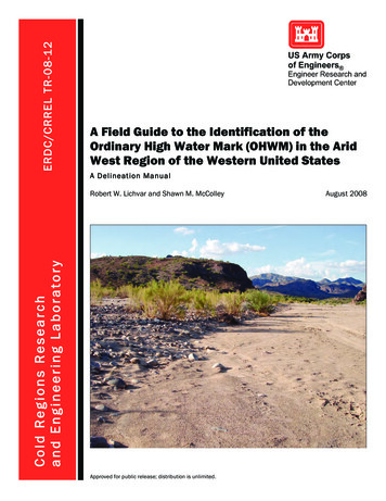
ERDC/CHL CHETN-III-72February 2006where Tm,d and Tm,u are minimum mattress thicknesses, H is the design wave height (assumebreaking wave height for depth-limited conditions or Hmo for nonbreaking waves), cot θ is theinverse of the revetment slope, Sr is the stone fill specific gravity (2.65 for granite-like rock), andp is the voids allowance of the stone fill (typically about 0.35). Equations 1 and 2 weredeveloped for gabions, so applying this guidance to marine mattresses is tentative until such timenew tests specific to mattresses are conducted. A safety factor should be considered for criticalapplications.Equations 1 and 2 are shown graphically on Figure 4 using typical values of Sr 2.65 and p 0.35. Cotangent of revetment slope is plotted on the abscissa, and wave height divided bymattress thickness is plotted on the ordinate. On slopes steeper than about 1-on-4 (cot θ 4) thedown-slope stability criterion (black line) governs. On milder slopes, the uplift stability criterionshould be applied. For example, a revetment with a slope of 1-on-2 should be able to resist waveheights up to about H 6 ft for a 12-in.-thick mattress or H 4 ft for an 8-in.-thick mattress.Securing the top of the mattress using anchors that extend landward beyond the soil failure zonewill provide additional protection against downslope failure. Once again, this stability guidanceis tentative, and caution must be exercised until additional tests become available.Figure 4.Marine mattress wave stability for revetment applications4
ERDC/CHL CHETN-III-72February 2006Underlayer for Rubble-Mound Structures. Larger coastal structures exposed to biggerwaves consist of a core covered by one or more underlayers of progressively larger stone, and anarmor layer of large stones or concrete armor units. Mattresses could be deployed as anunderlayer for some rubble-mound structures. If placed as the layer directly beneath the primaryarmor, the mattress container will help retain underlayer material if the overlying armor isdisplaced, thus preserving structure integrity until repairs can be made. In addition, the mattresscontainment allows use of smaller stones than would normally be needed to meet filterrequirements for unconfined underlayers. However, mattresses will be less permeable as a firstunderlayer than conventional stone underlayers resulting in more wave runup/overtopping. Thiscould allow greater hydrostatic head differential within the rubble-mound structure. Underlayermattress thickness should be about 6 in. minimum. This thickness provides good weight andrigidity for underwater placement, and mattresses can be filled while laying horizontal.Because of the geogrid smoothness and the uniformity of the mattress surface, the interfacebetween the mattress and the overlying layer has less shear resistance than a comparableunconfined underlayer. Thus, there could be a greater risk of armor layer slumping on steepslopes with a marine mattress underlayer unless a reliable toe is placed. In more energetic waveclimates requiring larger armor stones, mattresses will not be appropriate as the first underlayer,but they might be suitable as the first sublayer over the structure core. For applications whereprimary armor is placed directly on top of marine mattresses, great care must be taken not todamage the geogrid containers. Whereas the geogrid is tough and can withstand impacts fromdropped armor stones, the geogrid can be torn if armor stones are pushed into place using anexcavator. Once torn, mattress performance is impaired, and progressive damage is possible.Toe Protection. Marine mattresses can be used for structure toe protection at locations wherethe toe is not exposed to direct breaking wave heights greater than about 5 ft. This wave heightis near the lower end of revetment stability guidance for 12-in.-thick mattresses shown inFigure 4. For breaking wave heights greater than 5 ft, toe protection should be designed usinglarger stone according to guidance given in the Coastal Engineering Manual (Burcharth andHughes 2002). Whereas it is best to have the toe protection mattress tied into the structure,mattresses can be placed at the toe of existing or recently completed structures in the same wayscour aprons are placed. Guidance is given in the Coastal Engineering Manual for widths ofscour aprons for vertical wall structures based on geotechnical and hydraulic criteria. Ifmattresses are placed as the structure-bedding layer for a rubble-mound structure, they can alsoserve as toe protection by extending the mattress beyond the structure toe. As scour occurs at theouter edge of the mattress, the outer portion of the mattress becomes buried, thus preventingfurther scour.Scour Mats at Inlets or Other Environments Where Fluid Erosional Forces AreSignificant. Scour blankets constructed of placed stone have long been used to stem scour thatoccurs at inlet jetties and breakwaters or erosion that occurs in riverine environments. Designguidance for stone blankets specifies a stable stone size and a layer thickness to provide adequatecoverage. Achieving adequate layer thickness for subaqueous placement is often difficult, whichhas resulted in specification of increased layer thickness to compensate for placementirregularities. Using marine mattresses for this application may or may not reduce stone size ormaterial quantities, but the mattresses are easier to place and they assure uniform coverage when5
ERDC/CHL CHETN-III-72February 2006placed underwater. Mattress thickness could be as little as 4 in. if the unit weight per area isdetermined to be sufficient to prevent movement or uplifting. When placed over erodiblematerial, the outer edges of the mattresses will self-bury to provide protection against additionalscour. If the bottom material is hard, the mattresses should be checked for potential uplifting atthe edges. Mattresses can also be installed to stabilize bedding stone at existing structures thatare experiencing erosion or subsidence in the vicinity of the structure toe.Scour Prevention Mats in Advance of Construction of Coastal Structures. Wherecurrents are strong, significant scour can occur during construction of groins, breakwaters, andjetties. For example, Lillycrop and Hughes (1993) described scour that occurred during construction of the Oregon Inlet, NC, terminal groin. Placing scour protection in advance ofconstruction reduces scour, and correspondingly, reduces the amount of material needed toachieve the structure cross section. Marine mattresses can be placed rapidly with uniformcoverage; and because of their size and stability against currents, scour protection could extendmuch farther in front of construction. Finally, the mattresses could also serve as foundation matsfor the overlying structure as it advances into deeper water.Structure Foundation Mats and Bedding Layers Where Erosion Is Problematic orFoundation Soil Strength Is Poor. Coastal structures are typically massive gravitystructures that exert significant loads on foundation soils. Constructing structures on poor soilswith lower strength has always been challenging. Marine mattresses will help distribute loadsover a larger area because the geogrid container reduces differential settlement where soilstrength varies. However, mattresses will not eliminate differential settlement, so this must beanticipated in the design. Stones in marine mattresses used solely for foundations and/orbedding layers are less likely to move around, and the mattresses may not require the high degreeof compaction and grading of stone fill as is required for mattresses exposed directly to waveimpact or tidal current influences. It is important to remember that placement of mattresses asfoundation mats does not guarantee a stable structure, and a geotechnical foundationinvestigation is always needed to determine whether the soil will support the overlying structure.Also, mattresses placed directly over sand or soil will not stop leaching of foundation materialexposed to flow. To prevent loss of underlying material, first place either a bedding layer ofsmaller stones or a geotextile fabric on the soil or sand. To facilitate placement of the geotextilefabric in subaqueous applications where waves or current make placement of geotextile fabricdifficult, the fabric can be preattached to the marine mattress with additional steps taken inprefabrication to help assure proper overlap of the fabric as the mattresses are placed. Geogridcan be procured with geotextile fabric already attached.Pipeline and Outfall Protection. Marine mattresses could conceivably be used to protectunburied pipelines exposed to current and wave action. The mattresses can be placed rapidly,and the monolithic weight restricts movement of the pipe. In addition, the porous nature of themattress dissipates wave energy. No design guidance is available at present to predict mattressstability under given wave action and/or current for this application. Pipelines running throughthe surf zone should always be buried to a depth beneath the expected profile erosion underworst-case scenario.6
ERDC/CHL CHETN-III-72February 2006Olsen (2001) listed circumstances that might be favorable for application of marine mattresses:a. Irregular subgrade surfaces on soft/poor soils.b. Steep slopes (above or below water).c. Areas prone to breaking wave energy, wave runup, or wave reflection.d. Saltwater environments.e. Offshore deployment or emergency type repairs.f. Locations where wave or flow conditions impact the stability of an existing structure’sperimeter or leading edge, e.g., protection against flanking of the structure.Specific examples of completed successful coastal projects that deployed marine mattresses arepresented in a later section of this technical note.ADVANTAGES OF MARINE MATTRESSES: Marine mattresses have several importantattributes that make them suited for coastal construction.Offsite Construction. Because marine mattresses can be easily lifted and moved, the unitscan be constructed away from the project site, transported by truck or barge, and placedaccurately using locally available equipment. This is particularly useful at sites with limitedspace for stockpiling materials.Fabrication Quality Control. The technique of mattress construction, and the ability to viewthe entire mattress after completed helps assure high quality mattresses before placement at theproject site.Locally Available Materials. Because marine mattresses require rock fill of relatively smallsize, many project sites have a local source of fill material. Thus, material transportation costsmay be reduced.Rapid Placement. Being able to place mattresses rapidly has an advantage when working inopen coast tidal environments with limited periods of slack water or where the wave climatedoes not provide lengthy time windows of relatively calm conditions. Rapid placement alsoreduces the time expensive equipment must be onsite and the need to construct cofferdams toaccomplish work in dry conditions.Underwater and Deepwater Placement. Controlled underwater placement of stoneblankets and bedding layers constructed of unconfined stone is difficult, particularly in deeperwater or in low visibility situations. Achieving correct layer thickness often involves placingmore stone than originally planned, and verifying layer thickness is costly and time consuming.Weak spots occur where the stone placement misses small patches or coverage is inadequate, andthese may be starting points for progressive damage. Marine mattresses help alleviate7
ERDC/CHL CHETN-III-72February 2006difficulties in underwater placement because they are large units with uniform thickness that canbe butted up to one another. However, achieving accurate placement is challenging so it may benecessary at times to cover the gap between adjacent mattresses with overlying mattresses. Alsoimportant is including an extra flap of geotextile fabric supported by geogrid on both edges ofthe mattress to assure coverage of the underlying soil. The U.S. Army Engineer District,Philadelphia, reported that a combination of Global Positioning System (GPS) and multibeamsonar allowed the crane operator at a recent installation to move mattresses in 1-ft increments toachieve coverage in depths up to 50 ft. Edges of mattresses not in contact with neighbors wereclearly seen on the imagery. An additional benefit of mattresses placed underwater is that stoneis not lost during installation because of the geogrid containment.Hydraulic Stability. The high-strength geogrid container creates large, monolithic units thatremain stable under wave and current conditions that would destroy unconfined structures builtwith substantially larger stones. Increasing stone size within the mattress does not increase theoverall mattress stability.Mattress Size Uniformity. Well-constructed marine mattresses have consistent dimensionsso they can be placed in patterns without large gaps between mattresses. This assures uniformcoverage for applications such as bedding, revetments, or scour blankets. However, it does notguarantee that underlying material will not be lost through gaps between mattresses. Damagedmattresses can be removed, and replacements fabricated to the same dimensions. However,removal of damaged mattresses is often difficult after the lifting bars are removed, so a betteroption might be in situ repair by stitching on additional geogrid (if accessible), or by simplycovering the damaged area with additional mattresses.Uniform Mattress Porosity and Energy Dissipation. Marine mattresses will haveuniform porosity and consistent energy dissipation characteristics if they are filled with similarsized stones and are compacted in a similar fashion to provide the same void ratio. Specificwave energy dissipation data for revetment applications are not available, but expect similar orslightly less dissipation than would be achieved for a revetment constructed of similar-sizestones to the same thickness. The mattresses have a rough, permeable surface that will reducewave runup compared to smooth, impermeable revetments.Strength and Flexibility. The geogrid containment structure is strong, and the completedmattresses are flexible enough that they conform to usual topography and bathymetry changes.For example, mattresses used in dikes or levees can cover the seaward slope, drape over thelevee crest, and extend down the backside slope. This stabilizes the structure crest and providesprotection to the backside slope against overtopping waves.Fill Material Is Confined. The confining geogrid of marine mattresses prevents the rock fillfrom being transported away from the application site to adjacent beaches. This confinement notonly preserves the integrity of the structure, but it also keeps adjacent areas free of loose stone.Marine mattresses have been in service at several locations for up to 10 years, and this indicatesgood service life for the confining geogrid. Data are insufficient at this time to specify long-termproject life, so designs expected to survive for longer periods should anticipate periodicinspection and maintenance to combat long-term aging effects.8
ERDC/CHL CHETN-III-72February 2006MATTRESS CONSTRUCTION AND INSTALLATION GUIDELINES: Tensar Corp.provides a set of recommended specifications for the Triton Marine Mattresses System availableat the Web site http://www.tensarcorp.com/. The mattress construction and installationguidelines in the following paragraphs are based on the Tensar Corp. specification document.Materials. The materials used in fabricating marine mattresses consist of geogrid, mechanicalconnectors, braided lacing, and stone fill.Structural geogrid. The geogrid is made of high-density polyethylene (HDPE) and/orpolypropylene (PP), and it is manufactured so there is complete continuity of all propertiesthroughout its structure. The geogrid material is stabilized against ultraviolet radiation deterioration. Two types of geogrid are used in construction of a mattress containment structure. Thestronger Type 2 uniaxial geogrid has a breaking tensile strength of 6,908 lb/ft, and it is used forall exterior sides of the mattress (top, bottom, and sides) and the lifting loops. Type 1 biaxialgeogrid has breaking tensile strength of 3,330 lb/ft, and it is used for interior compartmentdividers.Mechanical connectors and braided lacing: Mechanical connectors used in mattressconstruction should be made of high-density polyethylene. These connectors resemble long rodshaving nominal diameter of three-eighths in. (Figure 5). Metal connectors should not be used.Braided lacing used for tying and lacing the geogrid panels into a mattress with interiorcompartments should be fabricated of high-density polyethylene eight-strand braid having anominal diameter not less than three-sixteenths in. and a breaking strength not less than 400 lb.The braid must be stabilized against ultraviolet deterioration. Braid lacing resembles tow ropesused by water skiers, but with ultraviolet (UV) stabilization (Figure 5).Stone fill. Stones used to fill the mattress compartments must be durable, free of cracks or otherdefects, and have specific gravity of at least 2.5. The absolute minimum stone size needed forretention within the mattress container is least 1.5 in. over the shortest dimension. The preferredminimum is 2.0 in. Maximum stone diameter should be about 6 in. The recommended averagestone diameter for a 12-in.-thick marine mattress should be about 4 in. A narrow distribution instone size will result in a more porous mattress than a well-compacted wide distribution wheresmaller stones fill the voids between larger stones.Fabrication. Marine mattress construction consists of fabricating the mattress containmentstructure, and then filling the containment with stones.Connections. The joints where the ends and baffles of each unit join the top or bottom of theunit should be made with a mechanical connector between geogrid elements as illustrated inFigure 5. Cable ties hold the mechanical connector rods in position prior to placement of the fillmaterial. Mechanical connectors carry the load when the units are lifted, and thus, are important.Stitched seams also carry load because they contain the rock fill.9
ERDC/CHL CHETN-III-72February 2006Figure 5.Mattress detail showing mechanical connector and braided lacing (photograph by KevinKnuuti, CHL)Seaming. Seams are stitched using lengths of braided lacing that have been knotted within 1 or2 in. of the ends to prevent unraveling. The starting end of the lacing is securely knotted to thegeogrid, and the seam joining two adjacent panels is laced with stitches spaced approximately sixper foot along the seam. The lacing must be stitched through each pair of apertures along theseam at least once, and the stitches must be sufficiently tight to close the gap between adjacentgeogrid panels. Figure 5 illustrates proper lacing of the panels. The braided lacing must beknotted to the geogrid at spacing not to exceed 6 ft along the seam. This technique reducespotential loss of material if the lacing fails. The seam is terminated by securely knotting thelacing to the geogrid. Pieces of braided lacing may be spliced end-to-end by securely knotting.Stone fill. The geogrid mattress containers are most often placed in a construction jig thatsupports the mattress vertically with the long dimension lying horizontal as shown in Figure 6.Mattress compartments are filled in lifts not to exceed 3 ft for loose material or 2.5 ft for packedstone. The final lift height should be less than 9 in. high, including a 2-in. overfill on thecompartment.10
ERDC/CHL CHETN-III-72February 2006Figure 6.Construction jig used to fill marine mattresses at Section 227 project in Seabrook, NH(photograph by Kevin Knuuti, CHL)Each lift should be tightly packed (except the final lift) by rodding and/or vibration. Compactedstone fill should exhibit the following characteristics: (a) tightly confined stones that will beimmobile within the mattress structure, (b) tensioned interior diaphragms, (c) snug mechanicalconnections and seams, (d) slight bulging of compartments, and (e) no evidence of air spacebetween compartments during lifting. Avoid overpacking of the compartment that causesexcessive bulging of the unit or interior diaphragms, and care must be taken that filling andcompacting does not cause excessive damage to the geogrid or laced seams. Mattresses intendedonly for foundation or bedding layers do not need to be as thoroughly compacted. Stitching thetop panel into place along the entire length completes the mattress filling operation.An alternate filling method is to place the mattress horizontal with the sides and diaphragms heldin place with removable wooden forms. Mattresses are filled using a front-end loader, fill iscompacted, and the top is then stitched onto the mattress. The next mat can be constructeddirectly on top of the completed mattress, resulting in a stack of mattresses. Horizontalconstruction is more efficient for thinner mattresses intended for underlayer or scour matapplication.Lifting loops are constructed on both ends of the mattress’ long dimension by joining the upperand lower geogrid layers as shown in Figure 1. Mechanical connectors must be used to securethe lifting loops to the mattress. Once completed, the mattress is rotated out of the constructionjig to a horizontal position, a lifting pipe and harness is fitted to the lifting loops, and the11
ERDC/CHL CHETN-III-72February 2006completed unit is moved by a crane to a staging area or placed on a flatbed truck for transport toa remote project site. If the mattress is to be placed on top of a geotextile filter cloth, it may befeasible to preattach the filter cloth to the bottom of the mattress with provision for sufficientoverlap of geotextile to assure complete coverage at placement.Installation: Marine mattress installation involves site preparation and placement of the units.Mattress anchoring might be specified for mattresses placed on slopes and exposed to wavesand/or current.Placement. Prior to mattress installation, the underlying layer (soil, sand, bedding layer, filterlayer, etc.) should be properly prepared, brought to specified grade, and compacted. Mattressunits should be placed in position at the proper elevation and in the proper alignment and patternas shown on the engineering drawings. Mattress units up to 35 ft in length can be lifted fromboth ends using spreader beams as illustrated in Figure 3 or from one end (as shown inFigure 11). The contractor may determine which method is most suitable based on certain siteconditions. Units should be lifted from the horizontal position in a manner that minimizes severebending or distortion of the top and bottom geogrid layers. The goal is to maintain fairlyuniform tensioning of the geogrid across the width.Units can be maneuvered into position using tag lines, but personnel must stay clear of the areabeneath units and support rigging at all times during lifting and placement. If divers are neededto guide underwater placement of mattresses, they must exercise extreme caution and adhere tothe dive plan. After initial placement, mattresses can be lifted and repositioned as finaladjustments are made. Generally, it is not necessary to connect adjacent mattresses once placed.If the mattress has a preattached geotextile filter, care must be taken to assure proper overlap ofthe fabric as the mattress is placed.Anchoring. Where specified, tieback anchors should be installed with the anchor point locatedlandward of any potential soil failure (e.g., slip surface failure), erosion of backfill, etc.Geotechnical engineers should be involved in this aspect of design.Repair. Damage to mattress geogrid or seams during fabrication, filling, or installation can berepaired provided damage is limited to relatively small areas. Seams can be relaced if theadjacent panels have not separated. If the rock fill has already been compacted, it may not bepossible to draw the seam together. In this case, a patch can be applied by stitching on a sectionof geogrid. Damage to the geogrid of filled mattresses should be repaired by stitching on a patchof new geogrid that covers the damaged area with at least 6 in. overlap in all directions. Damageto the mattress container prior to filling with stone should be repaired by replacing the entiredamaged geogrid panel.Mattresses that have been damaged after being put into service on a project can be either repairedin situ or removed and replaced with new mattresses. In situ repair requires replacing any loststones and applying a patch as previously described. This should only be done for smallbreaches of the geogrid or seams, and preferably only on mattresses th
ERDC/CHL CHETN-III-72 February 2006 where Tm,d and Tm,u are minimum mattress thicknesses, H is the design wave height (assume breaking wave height for depth-limited conditions or Hmo for nonbreaking waves), cot θ is the inverse of the revetment slope, Sr is the stone fill specific gravity (2.65 for granite-like rock), and p is the voids allowance of the stone fill (typically about 0.35).