Transcription
High-voltage reinforced isolation:definitions and test methodologiesAnant S KamathSystems Engineer, Isolation, Interface GroupTexas InstrumentsKannan SoundarapandianGeneral Manager, Motor DriversTexas Instruments
Understanding the definitions of high-voltage isolationparameters, their relevance to real applications, andthe methodologies used to test them, allows systemsengineers to pick the right isolator for their design need.Designing systems involving high voltage and high-voltage isolation is complicated.How much isolation do I need in my system? What system level isolation standardsapply to my product or end equipment? Are there component-level standards that helpme compare between isolators, and choose the one that best fits my system level need?Which parameters or metrics should I compare – there seem to be many? What are thetest procedures that isolation components go through to support the parameters in theirdatasheets? And foremost, how do I make sure that I am building a system that ensuresreliable operation throughout my product’s lifetime? These are questions faced by manysystems engineers dealing with high voltage and high-voltage isolation.Isolation is a means of preventing DC and unwantedAC currents between two parts of a system, whileallowing signal and power transfer between thosetwo parts. Electronic devices and semiconductorICs used for isolation are called isolators. Isolationis required in modern electrical systems for avariety of reasons. Some examples are to preventelectrical shock to human operators and preventingdamage to expensive processors, ASICs or FPGAsin high-voltage systems, breaking the ground loopin communication networks and communication tohigh-side devices in motor drive or power converterif the first barrier fails. This is called double isolation.systems. Examples of applications that needTo make systems compact and save cost, it isisolation include industrial automation systems,desirable to have only one level of isolation that hasmotor drives, medical equipment, solar inverters,the required electrical strength, reliability and shockpower supplies and hybrid electric vehicles (HEV).protection of two levels of basic isolation.This is called reinforced isolation.When isolation is used to enable the system tofunction properly, but not necessarily to serve as aHigh-voltage isolation performance of an isolatorbarrier against shock, it is called functional isolation.is quantified at the component level by parametersWhere isolation provides sufficient protection againstsuch as maximum repetitive peak voltage (VIORM),electrical shock as long as the insulation barrier isworking voltage (VIOWM), maximum transientintact, it is called basic isolation. Safety regulationsisolation voltage (VIOTM), isolation withstand voltagerequire basic isolation to be supplemented with a(VISO), maximum surge isolation voltage (VIOSM)secondary isolation barrier for redundancy, so thatand comparative tracking index (CTI) amongthe additional barrier provides shock protection, evenothers. These parameters represent the isolator’scapability to handle high-voltage stresses ofHigh-Voltage Reinforced Isolation: Definitions and Test Methodologies2August 2019
different magnitude and transient profiles, and haveThis document discusses test procedures anda direct mapping to realistic operating situations.results from high voltage testing on the ISO7842.The definitions and test methodologies for theseTest results demonstrate the exceptional high-parameters are described in component-levelvoltage performance and reliability of this device, andstandards such as IEC 60747-5-5, VDE 0884-10enable the system engineer to solve the toughest ofand UL 1577. Test methodologies differ slightlyisolation problems with confidence.for basic and reinforced isolators, and are moreespecially for magnetic and capacitive couplersMaximum transient isolation voltageand isolation withstand voltageor isolators.Maximum transient isolation voltage (VIOTM) and theWhen isolators are used in real applications,isolation withstand voltage (VISO) are both intendedsystems and end equipment standards alsoto quantify the ability of an isolator to handle highmandate certain minimum values of these isolationvoltage across the isolation barrier for very shortparameters depending on the system line voltage,periods of time. During normal operation, theand based on whether basic or reinforced isolationstress voltage across the isolation barrier is limitedis required. IEC 61800-5-1 (safety standard forby the maximum system line voltage. However,adjustable speed electrical drives), IEC 60664-1unintentional disturbances in the system, for(insulation coordination for equipment within low-example, noise on the supplies caused by arcing orvoltage systems) and IEC 61010-1 (safety standardload changes, could briefly cause the voltage acrossfor measurement, control and lab equipment) arethe isolator to be several times the line voltage. Theexamples of systems and end equipment standards.isolator should be able to handle these transientstringent for the latter. VDE 0884-10 is definedover-voltages without damage.This document discusses, in detail, the definitionsof the above mentioned high-voltage IsolationVIOTM is defined by IEC 60747-5-5 and VDE 0884-10parameters, their relevance to real-life systemas the peak transient voltage that the isolator canscenarios, and describes how they are tested andhandle without breaking down. This is tested duringcertified. This understanding is essential to comparecertification by stressing the isolator at VIOTM forthe performance of competing isolation solutions,60 seconds, followed by a partial discharge test atto decide whether an isolator meets system-level1.6 times VIORM for 10 seconds (see next section forisolation requirements, to determine if an isolator canthe definition of VIORM). This is called Method A testing.be used for reinforced isolation, and to judge theVIOTM is tested in the production manufacturinglong term reliability of an isolator.process by stressing every device at VIOTM for onesecond, followed by a partial discharge test at 1.875The ISO7842 is a robust electromagnetictimes VIORM for one second. This is called Method B1compatibility (EMC), high-speed, high common-testing. Partial discharge is localized discharge insidemode transient immunity (CMTI), quad-channelthe insulation material and is indicative of insulationreinforced digital isolator. It uses capacitance-basedintegrity. More details on Method A and Method B1isolation with silicon-dioxide (SiO2) as the dielectric.test profiles can be found in the appendix.This device uses advanced processing technology,precise packaging technology, and innovative circuitThe value of VIOTM also can be used to determinedesign, to deliver industry-leading high voltage andcompliance to system-level standards, such as theelectrical performance.IEC 60664-1, that require a certain level of temporaryHigh-Voltage Reinforced Isolation: Definitions and Test Methodologies3August 2019
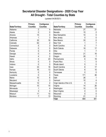
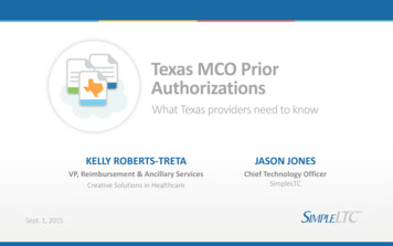
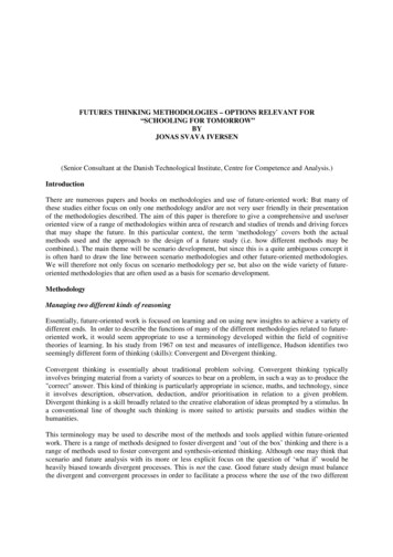
overvoltage to be tolerated by an insulation barrier,2000 devices. Also, each and every ISO7842 devicefor five seconds, depending on the system voltage.will be production-tested per Method B1, with theFor example, an isolator with a VIOTM of greaterstress voltage greater than 6840 Vrms to meet ULthan 6222 Vpk (4400 Vrms) meets the temporaryrequirements. These levels of VISO and VIOTM are theovervoltage criterion for reinforced insulation perhighest offered by any isolator in the industry in aIEC 60664-1 for line voltages up to 1000 Vrms.standard 16-pin SOIC package.VISO is defined per UL 1577 as the rms valueIt must be noted that ISO7842 easily meets theof voltage that the isolator can handle without4400 Vrms requirement for temporary overvoltagebreakdown for 60 seconds. It is tested duringrequired for reinforced isolation as per IEC 60664-1certification by applying a sinusoidal stress of VISO forfor line voltages up to 1000 Vrms.60 seconds. In production VISO is tested by stressingsinusoidal stress VIOTM and VISO are equivalent.Maximum repetitive peak voltageand working voltageTI tests its digital isolators to comply with UL,Maximum repetitive (VIORM) and working voltageIEC and VDE requirements. To perform testing(VIOWM) are both intended to quantify the ability of anfor VIOTM or VISO, an HT9464 high-voltage isolationisolator to handle high voltage across its barrier on aevery device for 1.2 times VISO for one second. Fortest system is used. This equipment is capable ofcontinuous, day-to-day basis, throughout its lifetime.applying the required transient overvoltage profileFor example, an isolator used to provide gate controlaccording to Method A and Method B1, as well asto a high-side IGBT in a motor drive system sees ameasuring partial discharge. This test is performedperiodic trapezoidal potential difference across itsby connecting all pins of side one and all pins of sideisolation barrier as the IGBT emitter, to which thetwo, then applying the voltage across the isolationisolator’s secondary side is referred, moves up andbarrier (Figure 1).down between high-voltage dc rails. This trapezoidalstress is present whenever the motor is operational.VCC 1IOsIOsIS O LA T IO NIOsIOsVIORM and VIOWM are defined in IEC 60747-5-5 andVCC 2GND 1IOsVDE 0884-10. VIORM is defined as the maximumIOsrepetitive peak voltage that the isolator canIOswithstand, whereas VIOWM is defined as the maximumIOsrms, or equivalent dc voltage, that the isolator canwithstand over a specified long term. For sinusoidalGND 2stress voltages, VIORM and VIOWM are equivalent. Bothvalues are specified by the manufacturer of theisolator based on the manufacturer’s testing.HT9464VDE 0884-10 Ed 1.0 and IEC 60747-5-5 check forVIOWM and VIORM through a partial discharge test thatFigure 1: Test setup for testing VIOTM and VISOlooks for localized discharges inside the insulationthat indicate degradation in the insulation. The partialThe ISO7842 meets a VISO of 5700 Vrms per ULdischarge test is performed along with the test forand a VIOTM of 8000 Vpk per VDE0884-10 and IEC60747-5-5. This is based on Method A testing overVIOTM using Method A tests during certification andmore than five wafer lots, and a total of more thanMethod B1 during production test.High-Voltage Reinforced Isolation: Definitions and Test Methodologies4August 2019
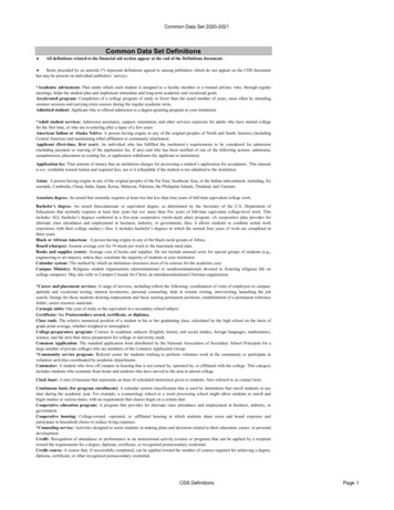
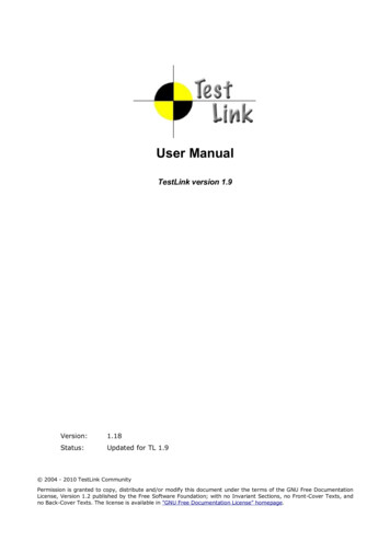
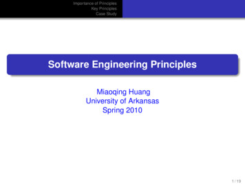
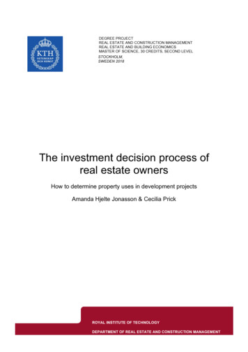
The soon to be released VDE 0884-10 Ed 2.0 alsoof 1.2, gives the value of VIOWM/VIORM. For a moreincludes an additional requirement on VIORM andcomprehensive understanding of the accelerated-VIOWM. To comply with this new upcoming standard,stress test and the related extrapolation, refer to thethe manufacturer of a reinforced isolator mustVDE 0884-10 Ed 2.0 standard.provide accelerated-stress test data to the certifyingAn accelerated-stress test is performed both at highagencies to prove that the isolator can handle 1.2temperature (150 C) as well as room temperaturetimes VIOWM/VIORM for more than 37.5 years. During(25 C).accelerated-stress tests, the isolator is subjected toThe values of VIORM and VIOWM derived from acceleratedvarying levels of high voltage, much higher than itsstress tests, as mandated by VDE 0884-10 Ed 2.0,expected working voltage, and the correspondinggive more confidence in the long-term reliability oftimes to breakdown are recorded. Then, the voltagethe isolator for continuously applied high voltage. Thevs. time curve is extrapolated for lifetime prediction atsame cannot be said about the partial discharge testthe expected working voltage. For isolators that usemandated by IEC 60747-5-5 and VDE 0884-10 Edsilicon-dioxide (SiO2) as the insulation material, the1.0, since there is no established relationship betweenrelation between time-to-failure and stress voltagelong-term withstand capability and partial discharge.follows an exponential relationship. Consequently,the log of expected time to failure reduces linearlyVCC 1with voltage stress applied. Therefore, VDE 0884-10VCC 2IOsrelation to curve-fit accelerated test data.IOsFigure 2 shows the test setup used to performIOsaccelerated-stress lifetime tests. All terminals onGND 1IOsISOLATIONIOsEd 2.0 requires SiO2-based isolators to use the sameIOsIOsIOsGND 2side one of the isolator are shorted together, andall terminals of side two of the isolator are shortedtogether. The required high voltage, a 60 Hz sineHighpotAR 7715wave, is applied between sides one and two tostress the isolation barrier using a high-voltagesource such as the AR7715 Highpot. The stressFigure 2: Setup for accelerated-stress lifetime tests.voltage is applied continuously until the impedanceFigure 3 shows the expected lifetime projection ofbetween side one to side two drops below 4 MΩ.the ISO7842 based on accelerated-stress testing ofAt each voltage point, batches of at least 32the isolation barrier used over five different wafer lotsdevices are stressed. The resulting times to failureand a total of more than 2000 devices. The shadedof the devices are fit to a Weibull distribution, andregion indicates the safe operating area (SOA) of thisstatistical analysis is used to find the time to failuredevice. Note that the actual test data is intentionallythat corresponds to 1 ppm failure rate. This time isnot shown in the figure. The SOA includes a factorthen plotted in the voltage vs. time to failure plot. Theof 1.2 de-rating as required by the standard andprocedure is repeated at different voltage points tois also based on a more conservative statisticalgenerate the entire voltage vs time to failure curve.extrapolation than required by the standard. TheThis curve, when extrapolated to greater than 37.5SOA can be used to estimate the expected lifetimeyears, and further de-rated by an extrapolation factorat any given operating voltage.High-Voltage Reinforced Isolation: Definitions and Test Methodologies5August 2019
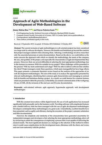
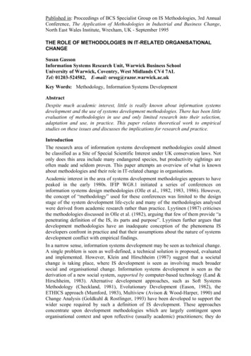
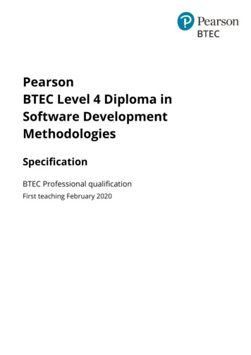
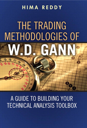
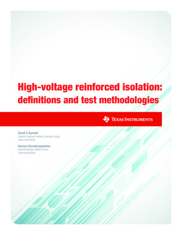
The 1 ppm line indicates that much less than onesupply mains (known as category III), operating atdevice in one million is expected to lie outside600 Vrms line voltages, IEC 61800-5-1, requiresthe SOA.a minimum surge capability of 8000 V forAs shown in the SOA curve of Figure 3, the ISO7842reinforced isolation.can withstand a VIORM of 2121 Vpk and a VIOWM ofNote that passing a surge test at levels greater than1500 Vrms for more than 40 years. These levels of10 kV has been widely used as the gold standard forVIORM and VIOWM are the highest offered by any isolatorreinforced isolation, though system level standardsin the industry, in a standard 16-pin SOIC package.allow for lower values of surge capability for systemswith lower line voltages.V IOWM 1.5 kVrms , 40 yearsV IORM 2121 Vpk , 40 years1.E 091.E 08V SURGE1.E 0690% V SURGE 1pp1.E 05mLife Time (Sec)1.E 071.E 04Safe Operating Area (SOA)1.E 0350% V SURGE1.E 021.E 011.E 0010% V SURGE010002000300040005000600070001.2 µsStress Voltage ( Vrms )50 µsFigure 3: ISO7842 lifetime versus stress voltage.Figure 4: Surge impulse profile.Maximum surge isolation voltageFigure 5 shows the setup used to test surgeperformance on the ISO7842. The isolator isMaximum surge isolation voltage (VIOSM) quantifiesconfigured as a two-terminal device by shorting allthe ability of the isolator to withstand very highthe left-side pins to one group, and all right-side pinsvoltage impulses of a certain transient profile. Theto another group. Surge voltage is applied acrosssurge test profile is shown in Figure 4. Surgethe isolation barrier using either the MIG1203 or thevoltages can be caused in an installation due toMIG2403 surge generators, depending on the testdirect or indirect lightning strikes, faults and shortvoltage required.circuit events. As per IEC 60747-5-5 andVDE 0884-10, an isolator claiming a certain VIOSMVCC 1must pass the surge test at a peak voltage ofVCC 2IOsISOLATIONIOs1.3 times VIOSM for basic isolation, and 1.6 times VIOSMIOsfor reinforced isolation. An isolator can be calledIOsreinforced at the component level, only if it passesIOsthe surge test at a level greater than 10 kV.IOsIOsIOsGND 1GND 2The passing level of a surge test is also used todetermine compliance to system-level standards,such as the IEC 61800-5-1, that require a certainMIG 2403level of surge capability for a given system voltage.Surge GeneratorFor example, for equipment connected directly toFigure 5: Surge test setup.High-Voltage Reinforced Isolation: Definitions and Test Methodologies6August 2019
The test is performed by applying 50 pulsesIEC 60664-1 classifies materials into four materialeach for both positive and negative polarities ofgroups according to their CTI values:the rated stress voltages. After the surge test, aMaterial group I:600 V CTIpartial discharge test per method B1, insulationMaterial group II:400 V CTI 600 Vimpedance test and a full functional production testMaterial group IIIa:175 V CTI 400 Vare performed on the device. A device is consideredMaterial group IIIb:100 V CTI 175 Vto pass the surge test if it successfully passes allCTI plays a major role in determining the minimumthese tests after applying the surge voltage. Tocreepage, or shortest distance along the surface ofavoid arcing through the air, this test is performed inthe isolator from pins on one side of the isolator todielectric oil.pins on the other side. A minimum creepage is re-Based on testing on greater than five wafer lots,quired for a given working voltage depending on theand a total of more than 2000 devices, the ISO7842extent of the pollution present in the systempasses the surge voltage test at greater thanenvironment. Using a mold compound with a higher12800 V. Since this exceeds 10 kV, it meets the limitCTI allows the use of smaller packages, and savesfor reinforced isolators. The rated value of VIOSM isboard space. For example, as per IEC 60664-1,8000 V, according to the scaling factor of 1.6a package with 8 mm creepage using a CTI-I moldrequired for reinforced isolation. Passing acompound can withstand up to 1600 Vrms of12800 V surge test also implies that this deviceworking voltage, whereas the same package using ameets the surge criterion for reinforced isolation forCTI-IIIa mold compound can withstand onlyequipment connected directly to supply main, for line800 Vrms.voltages up to 1000 Vrms, as per IEC 61800-5-1.The ISO7842 uses a CTI-I mold compound. Thisimplies that it can actually enable a 1500 VrmsComparative tracking indexworking voltage at the system level with a standardWhen an isolator is placed on a system board as8 mm creepage SOIC-16 package. In contrast,part of end equipment in addition to its internalcompeting isolators using a CTI-IIIa mold compoundisolation parameters, the mold compound usedin the same package can only enable a workingin its package is important. This is because whenvoltage of 800 Vrms at the system level, even thoughhigh voltage is applied across the isolator, electricthey may claim a higher value of VIORM/VIOWM at thedischarges on or close to the surface of thecomponent level.package, can cause localized deterioration in themold compound, resulting in a partially conductingDistance through insulationpath from one side of the isolator to the other.Distance through insulation (DTI) is the smallestThis phenomenon is called tracking. The ability ofdistance between the two voltage domains ina material to withstand tracking is quantified by athe isolator internal to the isolation package.comparative tracking index (CTI).Many end-equipment standards such as the IEC60601-1 (medical electrical equipment standard)specify a minimum required distancethrough insulation.High-Voltage Reinforced Isolation: Definitions and Test Methodologies7August 2019
ConclusionsHowever, these standards have provisions that allowthinner insulation layers, provided they pass certainThe high-voltage isolation performance of antests. These tests are a subset of the type testsisolator is quantified with different parameters, whichrequired per VDE 0884-10.represent the isolator’s capability to handle high-Historically, a higher DTI was a direct indicationvoltage stresses of different magnitude and transientof isolation performance based on the insulationprofiles. Various component-level standards definematerial used. However, due to the new generationthese parameters and the methodologies to testof magnetic and capacitive isolators using higherthem. This white paper discusses in detail thequality insulating materials, a very high isolationdefinitions of theseperformance can be obtained by a muchparameters, theirsmaller DTI.relevance to real-lifeThe ISO7842 has a minimum internal DTI of 21 µm,system scenarios,with a typical DTI of 25 µm. However, the breakdownand describes howstrength of the dielectric material used, SiO2, is verythey are tested andhigh at 800 V/µm. The quality of the dielectric usedcertified.is the reason for this device’s superior high-voltageResults from tests on TI’s ISO7842 reinforcedperformance.digital isolator, performed according to standardThis device meets the type test criteria of VDEprocedures, are presented. This device meets the0884-10 for reinforced isolation, proving that a DTI oftransient overvoltage and surge requirements for25 µm using material with 800 V/µm of breakdownreinforced isolation at both the component andstrength is not a matter of concern.system level, and enables reliable operation formany years in the presence of continuous, high-Table 1. Performance summary of the ISO7842NoParameterStandardValue1VISOUL 15775700 Vrms2VIOTMVDE 0884-10 Ed1.0 and Ed 2.08000 Vpk3VIORMVDE 0884-10 Ed1.0 and Ed 2.02121 Vpk (for 40 years)4VIOWMVDE 0884-10 Ed1.0 and Ed 2.01500 Vrms (for 40 years)5VIOSMVDE 0884-10 Ed1.0 and Ed 2.08000 V (surge test pass level 12.8 kV)6CTIIEC 60664-1CTI 600 material group: I7DTINAoperating voltage. The test results demonstrate thatthis device marks a significant leap in TI’s capacitivehigh-voltage isolation capabilities, and at thesame time delivers industry-leading, high-voltageperformance.21 µm (min) / 25 µm (typ)Note: Breakdown field for SiO2 is800 V/µmNotes:1. ISO7842 also meets the VISO, VIOTM, VIORM and VIOWM values mentionedin Table 1 per IEC 60747-5-5. However, the ISO7842 will not be certified toIEC 60747-5-5 as that standard is specific to optocouplers and notcapacitive couplers.2. VDE 0884 Ed 2.0 (soon to be released) is a revision of VDE 0884 Ed 1.0.It has tighter constraints and additional requirements over IEC 60747-5-5and VDE 0884 Ed 1.0 for VIOWM and VIORM.High-Voltage Reinforced Isolation: Definitions and Test Methodologies8August 2019
References1. IEC 60747-5-5 Ed 1.1, Semiconductor devices – Discrete devices – Part 5-5: Optoelectronicdevices – Photocouplers, May 20132. DIN V VDE V 0884-10 Ed 1.0, Semiconductor devices – Magnetic and capacitive couplers forsafe isolation, Dec 20063. UL 1577 Ed 4.0, Standard for Safety for Optical Isolators, May 20004. IEC 61800-5-1 Ed 2.0, Adjustable speed electrical power drive systems, safety requirements,electrical, thermal and energy, July 20075. IEC 60644-1 Ed 2.0, Insulation coordination for equipment within low-voltage systems, principles,requirements and tests, Apr 20076. IEC 61010-1 Ed 3.0, Safety requirements for electrical equipment for measurement, control,and laboratory use, general requirements, June 20107. ISO7842 product folder8. ISO7841 product folder9. ISO7821 product folder10. Reinforced Isolation meets unmatched performance11. Sarangan Valavan, Understanding electromagnetic compliance tests in digital isolators,White Paper, Texas Instruments, November 2014AppendixMethod AMethod B1V ini V IOTMt ini 60sV m 1.6 x VIORMt m partial dischargemeasuring time 10sV iniV iniVmVmV IORMV ini V IOTMt ini 1sV m 1.875 x VIORMt m partial dischargemeasuring time 1sV IORMt initmFigure 6: Simplified Method A test profile.t initmFigure 7: Simplified Method B1 test profile.Important Notice: The products and services of Texas Instruments Incorporated and its subsidiaries described herein are sold subject to TI’s standard terms andconditions of sale. Customers are advised to obtain the most current and complete information about TI products and services before placing orders. TI assumesno liability for applications assistance, customer’s applications or product designs, software performance, or infringement of patents. The publication of informationregarding any other company’s products or services does not constitute TI’s approval, warranty or endorsement thereof.The platform bar is a trademark of Texas Instruments.All other trademarks are the property of their respective owners. 2019 Texas Instruments IncorporatedSLYY063A
IMPORTANT NOTICE AND DISCLAIMERTI PROVIDES TECHNICAL AND RELIABILITY DATA (INCLUDING DATASHEETS), DESIGN RESOURCES (INCLUDING REFERENCEDESIGNS), APPLICATION OR OTHER DESIGN ADVICE, WEB TOOLS, SAFETY INFORMATION, AND OTHER RESOURCES “AS IS”AND WITH ALL FAULTS, AND DISCLAIMS ALL WARRANTIES, EXPRESS AND IMPLIED, INCLUDING WITHOUT LIMITATION ANYIMPLIED WARRANTIES OF MERCHANTABILITY, FITNESS FOR A PARTICULAR PURPOSE OR NON-INFRINGEMENT OF THIRDPARTY INTELLECTUAL PROPERTY RIGHTS.These resources are intended for skilled developers designing with TI products. You are solely responsible for (1) selecting the appropriateTI products for your application, (2) designing, validating and testing your application, and (3) ensuring your application meets applicablestandards, and any other safety, security, or other requirements. These resources are subject to change without notice. TI grants youpermission to use these resources only for development of an application that uses the TI products described in the resource. Otherreproduction and display of these resources is prohibited. No license is granted to any other TI intellectual property right or to any thirdparty intellectual property right. TI disclaims responsibility for, and you will fully indemnify TI and its representatives against, any claims,damages, costs, losses, and liabilities arising out of your use of these resources.TI’s products are provided subject to TI’s Terms of Sale (www.ti.com/legal/termsofsale.html) or other applicable terms available either onti.com or provided in conjunction with such TI products. TI’s provision of these resources does not expand or otherwise alter TI’s applicablewarranties or warranty disclaimers for TI products.Mailing Address: Texas Instruments, Post Office Box 655303, Dallas, Texas 75265Copyright 2019, Texas Instruments Incorporated
results from high voltage testing on the ISO7842. Test results demonstrate the exceptional high-voltage performance and reliability of this device, and enable the system engineer to solve the toughest of isolation problems with confidence. Maximum transient isolation voltage and isolation withstand voltage Maximum transient isolation voltage (V .