Transcription
TJ12HYDRAULICTRACK JACK(10 TON)USER’S MANUALSafety, Operation and Maintenance 2016 Stanley Black & Decker, Inc.New Britain, CT 06053U.S.A.72713 9/2016 Ver. 1
TABLE OF CONTENTSRepair Kits. 13Maintenance & Care.8 - 10General. 8Cleaning. 8Hydraulic Fluid. 8Replacing Fluid When Necessary. 8Annual Hydraulic Fluid Change. 8Purging Air. 9Inspecting the track jack for damage or leakage. 10Operation. 11-12Pre-Operation Instructions. 11Raising A Load. 11Lowering A Load. 11Horizontal Operation. 11Safety Precautions.5 - 6Tool Stickers and Tags. 7Specifications. 13Troubleshooting. 12Pump Assy Illustration & Parts List .14Base Illustration & Parts List .15Warranty.See BelowIMPORTANTTo fill out a Product Warranty Validation form, and for information on your warranty,visit Stanleyhydraulics.com and select the Company tab, Warranty.(NOTE: The warranty Validation record must be submitted to validate the warranty).SERVICING: This manual contains safety, and operation instructions. Stanley Hydraulic Toolsrecommends that servicing of hydraulic tools, other than routine maintenance, must be performed by an authorized and certified dealer. Please read the following warning.DANGERSERIOUS INJURY OR DEATH COULD RESULT FROM THE IMPROPERREPAIR OR SERVICE OF THIS TOOL.REPAIRS AND / OR SERVICE TO THIS TOOL MUST ONLY BE DONEBY AN AUTHORIZED AND CERTIFIED DEALER.2 TJ12 User Manual
NOTESTJ12 User Manual 3
SAFETY SYMBOLSSafety symbols and signal words, as shown below, are used to emphasize all operator, maintenance and repairactions which, if not strictly followed, could result in a life-threatening situation, bodily injury or damage to equipment.This is the safety alert symbol. It is used to alert you to potential personalinjury hazards. Obey all safety messages that follow this symbol to avoidpossible injury or death.This safety alert and signal word indicate an imminently hazardous situation which, if not avoided, will result in death or serious injury.This safety alert and signal word indicate a potentially hazardous situationwhich, if not avoided, could result in death or serious injury.This safety alert and signal word indicate a potentially hazardous situationwhich, if not avoided, may result in minor or moderate injury.This signal word indicates a potentially hazardous situation which, if notavoided, may result in property damage or damage to the equipment.This signal word indicates a situation which, if not avoided, may result indamage to the equipment.Always observe safety symbols. They are included for your safety and for the protection of the tool.LOCAL SAFETY REGULATIONSEnter any local safety regulations here. Keep these instructions in an area accessible to the operator and maintenance personnel.4 TJ12 User Manual
SAFETY PRECAUTIONSTool operators and maintenance personnel must always comply with and work in accordance with thesafety precautions and instructions given in this manual and on the stickers and tags attached to the tooland hose.These safety precautions are given for your safety. Review them carefully before operating the tool andbefore performing general maintenance or repairs.Supervising personnel should develop additional precautions relating to the specific work area and localsafety regulations. If so, place the added precautions in the space provided.GENERAL SAFETY PRECAUTIONS The user must be familiar with correct operation, maintenance, and use of the jack. Lack of knowledgecan lead to personal injury. Operator must start in a work area without bystanders. The operator must be familiar with all prohibitedwork areas such as excessive slopes, dangerous terrain conditions and extreme climates. Always wear safety equipment such as goggles, gloves, head, and safety shoes at all times whenoperating the tool. Warning: Hydraulic fluid under pressure could cause skin injection injury. If you are injured by hydraulicfluid, get medical attention immediately. The total load lifted or supported by the jack must never exceed the rated capacity. Excess pressurecan result in personal injury. Use a jack with sufficient capacity to lift a load. Keep clear of lifted loads. Before each use visually inspect the jack to prevent unsafe conditions from developing. Do not usejacks that are damaged, leaking, altered or in poor condition. See “INSPECTING THE TRACK JACKFOR DAMAGE OR LEAKAGE” on page # 10 for additional information. Properly support the jack. Do not put poorly balanced or off-center loads on the jack pad or jack. The load can tip and causepersonal injury. Do not use in unstable or hazardous positions. The jack must be used on flat surfaces to be able to carry the load correctly. The base must be completely supported. Do not push or lift on the ends of the base. Do not lift people, or loads with people on them. As the load is lifted, use blocks or cribs to guard against a falling load. To prevent personal injury, do not allow personnel to go under, or work under or on a load before it isproperly secured by suitable means. All personnel must be clear of a load before lowering or lifting. Lift only dead weight loads. Do not add additional weight to a lifted load. Do not use jacks that are damaged, altered or in poor condition. Do not modify the jack in any way thatwould affect the compliance of the jack with standard BS EN 1494:2000 A1:2008. The reservoir must have sufficient hydraulic fluid to fully stroke the jack. Use only approved hydraulicfluids.TJ12 User Manual 5
SAFETY PRECAUTIONSGENERAL SAFETY PRECAUTIONS CONTINUED: Read and understand the operating instructions in this manual, and the ASME B30.1 and EN 1494safety code for jacks. Users must ensure that all safety related decals and stickers are whole and readable. Replace thosewhich become unreadable. Never use extreme heat to disassemble a hydraulic ram or cylinder. Metal fatigue can lead to unsafeconditions. Be aware of possible "pinch points" of the jack, and stay clear to avoid personal injury. When lifting with the edge of the lifting toe, place a wedge between the load and the top of the liftingtoe to avoid bending the cylinder column. Carry the jack only by the carrying handle. Make sure the jack is in the fully lowered position. End users must be trained in the proper use of the jack. Remove operating levers when not in use to avoid accidental dislocation of the jack, and reduce thetripping hazard. Make sure all personnel are clear of the load before lifting or lowering. DO NOT use extenders or accessories unless they are rated for the load, injury or death could result. Never use this tool when working around electrified rail unless it is de-energized or you have beenproperly trained to work on electrified rail. If you are not sure the rail is live or not, you must treat it asbeing live and dangerous to life. The operator should always have the lifting device and load in view during movement. To avoid personal injury or equipment damage, all tool repair, maintenance and service must only beperformed by authorized and properly trained personnel. Never use the tool in an explosive atmosphere, sparks could ignite explosive gas.6 TJ12 User Manual
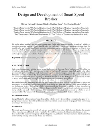
TOOL STICKERS AND TAGSMANUAL STICKERP/N-28788CRUSHING HAZARDP/N-31064STANLEY STICKERP/N-73679RAILROAD HELPDESK STICKERP/N-73680Model Number, Serial Number, 7250PSI/500 Bar and year of manufacture arestamped in this location on each jack.TJ12 User Manual 7
MAINTENANCE & CAREGENERAL PROTECTIONADDING HYDRAULIC FLUIDStore the Track Jack in an upright position, in a placewhere it is protected from the elements, abrasive dust,and damage.A jack that is low on hydraulic fluid will still be able tolift a full load, but not to the full lift height. As the reservoir begins to run dry, the handle lever becomes veryeasy to pump, and the jack stops lifting, this is a sign thejack is low on fluid.Use only recommended repair and replacement partsand materials specified in the Parts List section of thismanual.Do not use the jack for applications it was not designedfor.Use the carrying handle to transport the Track Jack fromlocation to location. Do not carry the Track Jack byinserting the jack handle in the socket.CLEANINGEstablish a routine to keep the jack as free from dirt aspossible – daily, or at each shift change, for example.Jacks exposed to rain, sand, or grit-laden air should becleaned prior to each use.Exposed screw threads should be cleaned and re-lubricated as necessary.Keep the cylinder clean at all times. Keep the pistonretracted when not in use.Operating lever and load-bearing surfaces should befree of slippery material or fluids.Keep tool labels and stickers legible.HYDRAULIC FLUIDThe Track Jack holds approximately 28 ounces/820 cccubic inches of hydraulic fluid (ISO#15) in its reservoir.DANGERDO NOT USE BRAKE FLUIDOR OTHER NON-APPROVEDSUBSTITUTE FLUIDS. LIGHTERWEIGHT FLUIDS MAY CAUSE THEJACK TO FAIL UNDER LOAD.8 TJ12 User ManualTo add oil:1. Fully retract the plunger.2. Make sure relief valve is closed.3. Remove the fill plug (item # 3 on the Pump AssyIllustration).4. Fill the reservoir with new, clean fluid (use ISO#15Hydraulic Fluid) to a level 1/8 inch below the bottom of the fill plug hole.WARNINGDo not overfill or underfill the reservoir as this may damage the jack.ANNUAL FLUID CHANGERegardless of usage, the Track Jack hydraulic fluidshould be changed annually to ensure proper operationof the jack. To drain the fluid:1. Thoroughly clean the area around the fill plug.2. Remove the fill plug and lay the Track Jack on itsback to allow the fluid to drain from the fill hole intoan appropriate receptacle.3. Dispose of the used hydraulic fluid in accordancewith Environmental Protection Agency regulations.4. Make sure dirt or other contaminants do not enterthe reservoir while the fill plug is removed. Whendrained, check the fluid for contaminants. If thefluid appears gritty or dirty, flush the reservoir withclean hydraulic fluid before refilling.5. Refill the reservoir with the recommended hydraulicfluid. Stand the jack upright, and with the pistonfully retracted, fill the reservoir until the fluid levelis 1/8 inch below the bottom of the fill plug.6. Before returning the jack to service, fully extend thepiston without a load by pumping the pump handlewithout the long extension handle. If the fluid levelis correct, the pump handle will become almost impossible to pump by hand as the piston reaches fullextension. Replace the plug.
MAINTENANCE & CARE7. It may be necessary to bleed air out of the cylinder.See instructions below for purging air.8. Inspect the jack for leaks, cracks, or other damage.DANGERFor Purging Remove CapAnd Loosen but do notremove the socket headcapscrew that is under thecap.CapImmediately take out of service anyjack that appears to be damaged orleaking.Oil Fill PlugPURGING AIRAir trapped within the jack hydraulic system can beremoved by performing the following steps.1. Make sure the plunger is fully retracted.2. Pry out the cap (see illustration at right).3. Loosen (Do Not Remove) the capscrew under thecap located in the top of the plunger.PRESSURE RELIEF SETTING4. Place the jack in a suitable fixture to prevent theextension of the plunger while purging air.The pressure relief is pre-set at the factory and should never bealtered. After the pressure relief is set at the factory the adjustment screw is made to not be tampered with.DANGERThe fixture used to prevent extensionof the plunger while purging air mustbe able to withstand the full ten tonforce of the jack.5. Add hydraulic fluid to the reservoir if necessary. Seeinstructions on page 8 for adding fluid.If you have any issues with the relief setting, please contactStanley Hydraulic Tools and ask for a customer service representative.The pressure relief is pre-set at the factory,never attempt to alter it’s setting. Alteringthe relief setting could result in death, serious injury or equipment damage.6. Pump the handle until oil comes up through thethread area of the capscrew in the plunger.7. Tighten the socket head capscrew to 10-12 ft.lbs./14-16 Nm. Then replace the cap.8. Top off the reservoir with hydraulic fluid. NOTE:Make sure the plunger is fully retracted before fillingthe reservoir.To avoid personal injury or equipmentdamage, all tool repair, maintenance andservice must only be performed by authorized and properly trained personnel.TJ12 User Manual 9
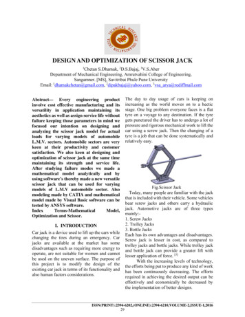
MAINTENANCE & CAREINSPECTING THE TRACK JACK FORDAMAGE OR LEAKAGE1. Before each use visually inspect the jack for leaks, cracks,or other damage.DANGERNever use a damaged track jack,Immediately take out of service any jackthat appears to be damaged or leakingand replace any damaged parts.CapRetaining RingLifting Toe2. Once a month it is recommended to remove the“Retaining Ring” and “Lifting Toe”, thoroughly inspectthe back as well as the front and sides for damage orcracks. Take special note of the areas indicated abovewith the black arrows.10 TJ12 User Manual
OPERATING INSTRUCTIONSDANGER4. Insert the jack handle fully into the handle socketand pump until the desired lift has been obtained.MAKE SURE THAT ALL PERSONNEL ARE CLEAROF THE LOAD BEFORE ATTEMPTING TO RAISEOR LOWER THE JACK. SERIOUS INJURY ORDEATH COULD RESULT FROM THE IMPROPERUSE OF THIS TOOL.WARNINGUse only the recommended length jackhandle. DO NOT use longer handles orextenders. See Spec’s on page 13.PREOPERATION PROCEDURESBefore putting a new Track Jack into initial service, or afteran extended period of being unused, perform a visual inspection for bent, broken, cracked, missing or worn components.(see “INSPECTING THE TRACK JACK FOR DAMAGEOR LEAKAGE”) on page # 10 for more information.Ensure the hydraulic fluid and lubricant level is correct.Fully extend and retract the jack without a load to ensure thatthe jack is primed and operating properly.5. Remove the jack handle from the handle socket oncethe load reaches its desired height.6. Crib or block the load to prevent accidently dropping of the load.LOWERING A LOAD1. Make sure all personnel are clear of the load.RAISING A LOAD1. Before using the Track Jack, make sure that it is set on afirm surface capable of bearing the intended load.2. Remove cribbing or blocking if used.3. Open the Spindle (item 41) by turning it counterclockwise (open slowly).2. Make sure the Spindle (item 41) is closed, by turning itclockwise until it is hand tight.DANGERLowering speed is controlled by opening the Spindlemore or less. Open slowly to controll the loweringspeed. Caution: Opening the Spindle too much willcause the load to drop quickly.DANGEROvertightening the spindle (item 41) candamage the valve seat. DO NOT use pliers orwrenches to tighten.3. Pump the handle by hand until the Toe Lift or Head Liftplate rises to and engages the load.Head LiftToe Lift4. When the load reaches the desired level, close theSpindle by turning it clockwise until it is hand tight.HORIZONTAL OPERATIONThe Track Jack can also be used horizontally to separatetwo items, as long as it is placed with the handle socketfacing upwards.1. Place the Track Jack base against the largest, heaviest, or otherwise least moveable of the two items.2.DANGERMake certain that the lifting toe is fullyengaged on the load, and the entire jack isstable, before proceeding further.Close the Spindle (item 41) by turning it clockwiseuntil hand tight.3. Pump the handle socket by hand until the lifting toeor the head of the lifting toe firmly engages the moremoveable of the two items.TJ12 User Manual 11
TROUBLESHOOTING4. Make sure personnel are clear of all items beingjacked before attempting to move anything.WARNING5. Insert the jack handle into the handle socket andpump until the desired separation has been obtained.6. Remove the jack handle from the socket once themoveable load reaches its desired separation.7. To free the jack, open the Spindle by turning it counterclockwise. When the lift plate is clear, close theSpindle.TROUBLESHOOTINGNEVER LIFT OR LOWER A LOAD HEAVIER THANTHE LOAD RATING OF THE JACK. DAMAGETO THE JACK OR LOAD COULD RESULT FROMIMPROPER USE OF THIS TOOL.PUMPING HANDLEA pumping handle is included with the Track Jack. DONOT use the pumping handle for any other purpose.DO NOT substitute other material for use as a pumpinghandle or use a longer handle than what is specified onpage 13 under specifications.If symptoms of poor performance develop, the following chart can be used as a guide to correct the problem.Because the Track Jack can be used for many different applications, this information is general in natureand does not address specific uses.PROBLEMCAUSECORRECTIONJack will not raiseA) Release valve not closedClose the valveB) Release valve ball notseating properlyHave jack serviced by a qualifiedtechnicianC) Seal failureHave jack serviced by a qualifiedtechnicianJack raises but will not holdRelease valve ball not seating properlyRelief valve set too low orMalfunctioningHave jack serviced by a qualifiedtechnicianSeal failureHave jack serviced by a qualifiedtechnicianJack only raises part wayHydraulic fluid level is lowAdd hydraulic fluid (See spec page)Jack leaks hydraulic fluidSeal failureHave jack serviced by a qualifiedtechnicianJack retracts slowlyAir in the hydraulic systemPurge air from the hydraulic systemJack raises, but pulses andhesitatesAir in the hydraulic systemPurge air from the hydraulic system12 TJ12 User Manual
SPECIFICATIONSSPECIFICATIONSPerformanceMaximum Lift . 8.8 in. / 22.3 cmMaximum Load. 10 tons / 9,072 kgPump Displacment.46 cu. in. / 7.5 cc stroke, single speedAdvance rate per stroke. 0.160 in. / 4.0 mmPressure at rated load. 7250 psi / 500 bar Model TJ12Maximum pump handle effort. 75 lbs. / 34 kgDimensionsBaseplate Size TJ12111S.6.000 x 11 in. / 15 x 28 cmBaseplate Size TJ12112S Narrow. 4.500 x 11 in. / 11.4 x 28 cmWeight . 45 lbs / 19.5 kgLift Toe Width and Depth. 2-1/2 in x 3 in. / 63 mm x 76 mmHeight (Retracted) . 14.7 in. / 37.3 cmHeight (Extended) . 23.500 in. / 597 mmNet Weight (with oil) no handle . 45 lb / 20.4 kgPump Handle Length (p/n-52813) . 36 in. / 91 cmHydraulic RequirementsReservoir Capacity . 28 oz / 828 ccRecommended Fluid. ISO #15 Hydraulic Fluid.Standards. ASME B30.1, EN 1494:2009Note.This product does not exceed 70 dBA per ISO 11201NOTE: Weights, dimensions and operating specifications listed on this sheet are subject to change without notice. Where specifications are critical to your application, please consult the factory.REPAIR KITSNOTE: For items in repair kits see both illustrationsand parts lists.Cylinder Repair Kit P/N-56522Includes Items: 1, 8, 19, 21, 26 thru 30.PUMP HANDLEASSEMBLY P/N-52813Reservoir Repair Kit P/N- 56524Includes Items: 24, 25 and 37TJ12 User Manual 13
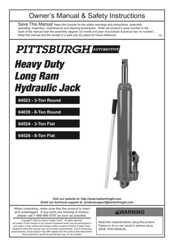
PUMP ASSY ILLUSTRATION & PARTS LISTITEMPART #1000552O-RING *2014111O-RING *3016711-6 HEX HD SAE PLUG4048551RETAINING RING EXTERNAL6052913STEEL BALL 7/327073271O-RING *8153982BACK-UP RING *For Cylinder Repair Kit & ReservoirRepair kit see page 13.QTY DESCRIPTION57213381STEEL BALL 5/32260051# 80 MASTER LINK11260391O-RING *12287881STICKER - MANUAL1024766971PUMP HANDLE ASSY (INCLUDES DU 1ROD WIPER *34565184HSHCS M8 X 2535565214HSHCS M6-1.0 X 1536714311COMPRESSION COIL SPRING37714781OIL TUBE38748631PUMP BODY ASSY (INCLUDES EXPANDER PLUGS)39717071O-RING*40726631CHECK VALVE SEAT ASSY(INCLUDES ITEM # 7)41717151SPINDLE42717161PISTON43717371RELIEF VALVE SEAT44717381SELF LOCKING SETSCREW46726641CHECK VALVE HOUSINGASSY(INCLUDES ITEM # 2)48736791NAME TAG - TJ1249736801RAILROAD HELP DESKSTICKER51764941BACK-UP RING*56767161GROOVED CLEVIS PIN57767171SCREW, M5 X .8MM X 10MMLONG58767181SPRING SEAT603500232HOLLOW HEX PLUG -3 SAE14 TJ12 User Manual33513412119(see both parts list for items included in seal kit)66010* DENOTES PART IN SEAL KIT (P/N-72735)41 34 394324378381975842604440362464825354926Complete PumpAssembly P/N74864Model #, Serial #Located here.TJ12111STJ12112S Narrow Base
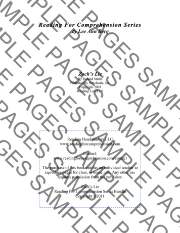
BASE ILLUSTRATION & PARTS LISTFor Cylinder Repair Kit &Reservoir Repair kit seepage 13.5519201416ITEMPART #QTYDESCRIPTION14310641CRUSHING HAZARDDECAL16528051CAP ASSY.17528061LIFTING TOE18528071STOP 2528111SPRING ASSEMBLY23528121BASE TJ1227565061RETAINING RING*28565071ROD WIPER *29565081ROD SEAL*30565091BACK-UP RING *31565101O-RING *32565121HSHCS M6-1.0 X 2555767141HSHCS M6-1.0 X 8027* DENOTES PART IN SEAL KIT P/N-7273521(see both parts list for items included in seal kit)1722TJ12111S232818293019Model #, Serial #Located here.3132TJ12 User Manual 15
NOTES16 TJ12 User Manual
Stanley Hydraulic Tools3810 SE Naef RoadMilwaukie, OR 97267-5698 USAPhone: (503) 659-5660Fax: (503) 652-1780www.stanleyhydraulics.com
Stanley Hydraulic Tools recommends that servicing of hydraulic tools, other than routine maintenance, must be per-formed by an authorized and certified dealer. Please read the following warning. . RAILROAD HELP DESK STICKER P/N-73680 MANUAL STICKER P/N-28788 CRUSHING HAZARD P/N-31064 STANLEY STICKER P/N-73679