Transcription
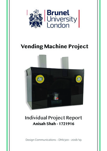
Vending Machine ProjectIndividual Project ReportAnisah Shah - 1721916Design Communications - DM2320 - 2018/19
ContentsAbstractBrief overview of team members,Project focus and task delegation.Initial IdeasCollation of key themes, brainstorming and sketches directing the path forthe project. Display of initial developments with evidence of agreed partnerdecisions.DevelopmentHousing development including different designs for exterior aesthetics,sketch modelling for sizing and internal component placement considerations.The second part of this section includes coding complications and resolutionsand flow charts depicting function and user feedback.Summary/ ConclusionSummarising the projects achievements and pitfalls will evaluate parts wherethe project excelled and targets to progress on for final year.Concluding and understanding the end outcome of the project will aiddevelopment within this field of design.
AbstractTeam Members - Anisah Shah & Malav PatelAnisah Shah1721916BA Industrial DesignMalav Patel1777112BA Industrial DesignThe Vending Machine Project was the second half of our DesignApplications module during Level Two Industrial Design. Thisconsisted of theoretical coding during term one with practicalapplications displayed through the Vending Machine Project.As Malav and I were friends before this project we decided topartner up as a pair. We discussed our individual strengths andweaknesses and delegated tasks early due to our tight deadlineswith other modules. We started off brainstorming together as ateam which helped us get an initial structure of the project andfinalize on an Idea. We then divided it up into housing and codingwith user Functions.The reality of the project entailed a last minute product switchdue to rushed functional testing. Though the vending machine’soriginal purpose was a spice dispensing kitchen seasoning station,the submitted product dispenses Tic Tacs. Breakdowns andevaluations will be made throughout the report highlighting criticalerrors creating setbacks for project completion.Although the project took a few major turns, our intentions andoverall project aspirations will be made clear in response tofeedback given to aid in the understanding of our vision. Mostof the logical step by step progress was extremely valuable indetermining the best design solution and will be made clearthroughout the report.The coherent report to follow will display mine and Malav’sapproach to the design brief set with a summary and conclusion atthe end to evaluate.
Initial IdeasInitial ideas included multiple themes for dispensing items. Combining mine andAnisah’s natural passions, we pursued a spice dispensing machine to provideappropriate flavour to current meals in the kitchen. This direction seemedapparent from the first session due to vast background interest in the proposeduse of the product.Multiple theme choices seemeddesirable at this point. Explorationinto possible items rangingfrom food & drink to games tostationary.As shown from our inital skittlesdesign, we were overcomplicatingthe design. For our early focuseddevelopment we initially consideredtwo ranging quantities of 1tbspand 1tsp. This would offer aperfect self / family portion splithowever given the space andcomplexity of the design we wereadvised to simplify.To ensure brief specificationswere met I created rough sketchmodels and drew possibledesigns.As the complexity issue was amajor one, the use of 3D scalemodels helped me perspectivelyview the design and iteratesimplified models.This helped funnel aestheticdesign perspectives for to help inour development stage.Implementing symmetry withinthe design gave me scope togive the product a professionalstyle. This would match thekitchen environment originallymeant for the design.Form the brief the size restrictions were 300 x 300 x 210 mm. We agreed upon abasic shape for the machine, splitting the dimensions into thirds. This gave a focusto the product as it channels your eyes to the focus of the shot glass. This shotglass is meant to be reusable and recyclable. The dry herbs and spices dispensedinto the glasses can be tipped onto food with the glass washed or wiped andplaced back.
Inital mood board reseach consised of exisitng product research.Most looked at where the colour schemes and styles of productswhich would follow the same function as ours. The main coloursare the integration of a contrasting colour with a jet or mattblack.As shown by the mood board images, the existing products helpmultiple spices although didnt dispense. This high bench markmade set our expectations too high in terms of functionality weneeded to achive.Our inital approach was to have multiple 4-6 spieces with atleast 2 quantity settings. This prioved much too complex forus to achive good user feedback. It was after contructing a 3Dmodels at the desiered specification, that we relised this was tooambisious. We therefore reduced this to 1 IR sensor, 1 StepperMotor, 2 LED lights and 2 Buttons controlled by an Aurduino UnoMicroprocessor.Unfortunaty due to testing failures, which will because moreapparent with later illustrations, we had to change our dispensingproduct. The dry spieces were creating too much spillageinternally and casuing our mechinism to jam casue by therecuring friction of the power. The incorporation of two flavouredtic tacs have use scoped to addapt the design whiled using thesame internal functional componetns.
DevelopmentFollowing our inital ideas, we looked further into the reality of our product. Sketchmodelling helps us gain an understanding about scale and proportion, howeverthe next stage of development included higher quaility ideation and accurate 3Dmedelling.We wanted the piece to look fit into a kitchenenviroment thus basing aesthetics on existingproduct styles. The jet black finish promotes asense of minimilsm with the symetical face proving aprofesssional clean look.With the intial spice dispensing design, the twospieces were loaded approprately into the hopper.The buttons below offer the option for the spice withthe larger buttons dispensing 1 tbsp and the smaller,1 tesp.The buttons would command the microprocessor todispese the select quanity and funenel the spice intothe shot glass.The IR sensor under the platform and the two LEDs offering product direction.vinyl stickers designs was added at this stage to test possible aesthetic outcomes.One major development included the decison to simply our product. Although whenspoken about our aim of 2 spieces dispenced with 2 quanities shown to complexto code. The numbours additional functions required would heavily effect our userfeedback. therefore a final decsion was made on the components. 1 IR sensor, 2 LEDlights, 2 buttons and 1 stepper motor. Below is the refined drawing.
The first main sketch model was madefrom cardboard. The internal structureswere planned to offer the best stabilityfor the product. this also cut downour time in the workshop as they weresimple shapes to manufacture andsupplied us with a platform to placeour stepper motor. The walls alsoallow us to isolate the direction of thefunnel and his all cable mechanismsout of sight. As shown later, this planeis also used for cable management asa calcualted cut out created a feedwhere the cables run. This allows theinteral structures to be more compact.Inital thinking was to create two planes,one rotating, one fixed, both withmeasured cuts. The rotaion of thestepper motor would allow the cutsto match and release a controlled andtimed quantity of spice. This wouldthen travel in a funnel to the shot glass.As the contents would be dry, and thefunnel would have a smooth surface,the spices should run off the face andinto the glass.The approach consists of two mainpieces. Both would be sub assembledin its extrety before being attachedtogether.Our main hurdle when taking on thisapprach was the consistancy of themovement. The mechanism, eventhough functionally designed, deemedto ineffiecnet for our product. Due tothe inability to differentiate betweenthe two rotations without a seconardystepper motor, this method needed tobe refined.
Stepper MotorItalian SpiceIndian SpiceWhen the 3D prototype was made, onemain issue became clear. The spaceallocated to funnel the spice may be toosteep to effectivley dispece. In addition tothe previous same plane rotation problemthe space was making the project harder.From here we designed a single planewhich spreads under both channels. weused a 2mm polymer sheet. Drilling andattaching surface support to the steppermotor allowed us to place this in thecentre of the polyer. We could now controlthe clockwise and anticlockwise rotation ofthe plan.The images on the left show the twosettings programmed on the arduino. Theplane is placed just infront of the opening.When the mechanism is activated, thestepper motor rotated 10 degrees eitherclockwise or anti clockwise depending onwhat button is pressed.The rotation reverts back to its originalposition once spiece has been dispensed.The timed mechanism and the angle ofrotation ensures minimal spillage of herbsinternally.This new developed mechanismhelps with our current problemsas it increases the height of dropallowing a reduced angle for thespice drop.Issues we found and overcamewith this mechanism included thepivot support which slanted theplane and the weight presseddown on either side, restricting themovement of the stepper motor.
The weight of the spieces putdownwards pressure on the two planecausing flex. This didnt allow the steppermotor to rotate. The solution to thiswas to create a foam washer to preventthe arylic to touch the motor. The foamoffered support and regidity to themovement.The stepper motor would be resting onthe lower plane. This gives it enoughsupport as double sided tape held itdown. The low density foam washerallowed a confortable fit with a largepossible surface area attachment to theplane.The compact cabelling allows spacearound the the sides fort the funelswith the wires channeling behind. Cablemanagement was an important factordue to the size of the rotating plane.The washers were created via a jigto ensure hole drilling is accuratewith all pieces.A minor injury in the workshop atthis stage reminded me to not cutcorners when working with highspeed machinary. The use of thisjig helped clamp down the piecesensuing a clean cut hole.The initial flowchart is shown on the leftillustrating the step by step process ofthe vending machine.From here coding developments tookplace with refinments to the code andthe flowchart. These adaptations werecreated through troubleshooting testsdone on the stepper motor.
Development - CodeDividing the functionality into different functional blocks:Components: Yellow LED 1Yellow LED 2Button 1Button 2IR SensorStepper motorAim:1.2.3.4.Container placed in collection point triggers IR sensorIR sensor triggers 2 LED lights to switch ONButton 1 activates the stepper motor to turn clockwiseButton 2 activates the stepper motor to turn anti-clockwiseCode for each step:Step 1: Container placed in collection point triggers IR sensor Void loop ( ) to loop 2 functions which are repeated continuously AnalogRead to identify Serial.println embedded if an ‘If’ statement to control the sensor readingStep 2: IR sensor triggers 2 LED lights to switch ON Continuation of ‘If’ statement in Step 1 with digitalWriteStep 3: Button 1 activates the stepper motor to turn clockwise Use of void clockwise ( ) Followed by ‘for (int n 0; n xyz : n )’ Function and digitalWrite to identify eachclockwise rotation of the stepper motor To run the motor loop that is triggered by the buttons being pressed, void motorfunction will be used along with digitalRead to rotate it clockwiseStep 4: Button 2 activates the stepper motor to turn anti-clockwise Use of void anticlockwise ( ) Followed by ‘for (int n 0; n xyz : n )’ function and digitalWrite to identify eachanticlockwise rotation of the stepper motor To run the motor loop that is triggered by the buttons being pressed, void motorfunction will be used along with digitalRead to rotate it anticlockwise
Detailed Flowchart
Initiation of CodeTo start off the code, as stated, some basic codes were needed to get thearduino to build a solid structure and get the mechanism going. To do this,after the declarations, these codes were applied;Void Set-upVoid setup helps establish eachcomponent as an output or an input for thearduino. In this instance, the buttons and IRsensor were inputs as they trigger a functionand the motor and LED lights were outputs asthey act upon an input.Void LoopVoid loop loops functions which are repeatedcontinuously. It loops, allowing the programto change and respond in regards to thearduino board. This approach stimulatesrunning both the functions at the same time.Each function runs one at a time.In this instance, if the CDS sensors reading isless than 200 the yellowled1 and yellowled2will stay turned off. If the sensor reading ismore than 200, yellowled1 and yellowled2will turn on.Stepper MotorFor the stepper motor, along with the voidloop and ‘if’ statement, it runs the ‘motor’ loopin which 2 buttons trigger either the clockwiseor anti-clockwise motion of the motor whichallows the tic tacs to come out and then return to its starting point to avoid spillage ofsweets.
Development of Code - TroubleshootingThroughout the project, various iterations of the code have been formulated.Starting from the most basic and building on it to test its functionality andtrack overall progress. Here are a few versions of the different codes thatwere further developed to derive the final code;Version 1:The first version of the code started off withdeclarations of the components, followed bythe void setup.We then moved on to the stepper motorrotations where we set the balanced rotationspeed of a 100 delay, between each steps.We also stated void clockwise ( ) at this point
TroubleshootingWhilst testing this code, werealised that the stepper motorwas not working alongside theLED lights and they both werenot running simultaneously. Wethen realized it was due to thefact that there was a need fora void loop for both the LED’sand the stepper motor straightafter the void setup and not atthe very end.
Version 2:To fix the problems faced in the first version,the void loop for both the lights and motorwas added straight after the void setup so thatthey can be run simultaneously.
Further TroubleshootingAs a result, the LED’s and the motor were working simultaneouslyhowever the motor was not functioning properly. We realized it wasbecause the void motor ( ) step was not correct. Even though in theory itseems correct but within the code it did not work and needed re-wording.This needed further troubleshooting to make the stepper motor work.
Final Modified Code - With annotationsAfter many different versions of developing the code, the intended code thatwas planned was achieved after troubleshooting with the previous codes.Trial and error was a big part of this process as it allowed us to see theresults of the code in real-time allowing us to make alterations as we goalong. The stepper motors delay of 100 gave a good velocity for the shaft toturn and allow a certain amount of sweets to exit into the container.Here is the final modified code with annotations;
Code OrganisationThe code was finally organised by:1. Declaring the components connections into the Arduino2. Declaring the inputs and the outputs3. Setting up the IR sensor with the Arduino4. Setting up the stepper motor and adjust the rotations into the Arduino5. Setting up the buttons into the ArduinoStaring off by declaring all of the components connected into the ArduinoVoid SetupVoid loopMotor rotations : Clockwise and Anti-clockwiseVoid motorCode Compactness:These were the brief steps which we used to organise out code and itworked best for our vending machine. It also gave a clear layout of whatcode results to what outcome. Having the code organised in such a way wasvery helpful when we were troubleshooting problems with the code as weknew which area to target when the motor or LED’s were not working. Iteliminated any confusion that could have been caused.Finally the reason why we organised, the coding as shown, was because ithas primarily a standard way of it to be done. So after defining thedeclaration, stating where every component was connected, we stated thevoid set up as its been read by the Arduino before and then went to definethe void loop.This then caused the motor rotations to take place which made it turn eitherclockwise or anticlockwise depending on which button was pressed.
Prototyping - Housing and StructureInternal and external components
IR Sensor housingThe cup sits on top of this platform whichtriggers the IR sensorInternal Layout and Cable managementThis gives a brief idea of how the internal layout of the vending machine will be. Italso shows cable management which is a key aspect of any electronic device. Wewanted to keep the cable management at a minimalistic view so that it does notinterfere with the internal mechanism.
Building Process and StructuringFollowing our initial ideas, we looked further into the reality of our product. Sketchmodelling helps us gain an understanding about scale and proportion, howeverthe next stage of development included higher quality ideation and accurate 3Dmodelling.Having sorted out the code and arduino andknowing the mechanism works, it was time to put itall together within the outer body and see how it allworks as a unit.To make the outer body, we used black acrylic as itwent with both the mint flavour of tic tacs and thefruity flavour of tic tacs. The reason we used Acrylicwas because it is sturdy and strong and can holdboth the tic tacs and the internal mechanism withease.To glue it all together we used plastic glue as itholds the plastic together very well.
We gave the users two options tochoose from, Mint tic tacs and Fruitytic tacs to cater to everyone’s needs.For the aesthetic, i edited 2 stickersthat were stuck onto the twobuttons.
Final Vending Machine
Conclusion & ReflectionTo conclude, since we were set this project, the idea of creating my veryown vending machine fascinated me and I was excited to learn new skillsthat i would now be applying into something that actually works. It mademe put all the Arduino coding into practice and see a result which I hadnever done before. The coding aspect of the project interested me a lotand I am glad I challenged myself to learn how to code in my own timeand do some hands on research. This led me to explore all the differentvariations of a simple command and how it can be executed.One main aspect of this project was that it was a group project and thistested me and my partner in both good and bad ways. One thing thatworked out well was that we delegated roles from the beginningaccording to our strengths and weaknesses - which essentially is whatgroup work is all about. We used this to allocate different parts of thewhole project and it worked out well for us. Having said that, due to thefact that we had a couple of other deadlines going on at the same timeas this project, we could not give it the proper time it needed and westruggled to complete everything in time. We had to rush our wholeproject which led to stress and unresolved technical problems.In regards to the code, we did well however, the mechanics aspect of thevending machine did not operate as well as we could have made it work.It all came down to time management and if we had more time we wouldimprove a lot such as : Improve the outer body and make it more aesthetically pleasing Improve the inner mechanism which is connected to the stepper motor so that the tic tacs come out with better flow We would have laser cut the parts instead of using a band saw We would have improved the cable management and make it moreeffectiveAll in all i have learnt a lot from this project and was happy with my skillsimproving. It was a challenging and stimulating project but it was worththe stress.
The Vending Machine Project was the second half of our Design Applications module during Level Two Industrial Design. This consisted of theoretical coding during term one with practical applications displayed through the Vending Machine Project. As Malav and I were friends before this project we decided to partner up as a pair.