Transcription
Installation GuideEaton Lightning Series TransmissionsTRIG0580October -15410CFRLOF-15410C-T2FRLOF-16410CFRLOF-16410C-T2
Table of ContentsTable of ContentsOverview . 1Transmission Features . 1Similarities to Current Eaton Fuller Transmissions . 1Significant Installation Differences from Current Eaton Fuller Transmissions . 2Related Publications . 2Specifications . 3Model Nomenclature . 3Gear Ratios and Steps . 3Shift Pattern . 4Options . 5Standard Features . 5Vehicle Interface - Mechanical . 6Dimensional Drawings . 6Engine Requirements . 6Master Clutch Requirements . 6Shift Lever Design . 8Internal Transmission Cooler Heat Transfer Capability . 10Fastener Information . 11PTO Interface . 13Vehicle Interface - Electrical . 14Vehicle Electrical Requirements . 14Vehicle Wiring Diagram . 20Transmission Application Approval . 21Transmission Application Approval Form . 21Transmission Application Approval Forms . 22Line Inspection . 24Pre-Start Checks . 24Dyno/Road Test . 24Appendix . 25Design Remedies for Shift Lever Jumpout . 25Technical Description of Jumpout . 25Ratios . 27Side View . 28Rear View . 29
OverviewOverviewThis manual has been prepared for OEM engineering personnel. It contains technical details on the new Eaton FullerLightning “FRLO-1X410C-T2 series model transmission.Information contained within this manual was accurate at the time of printing. However, you should contact your EatonFuller Engineering representative prior to start of engineering for a new application.Transmission Features Ten forward and two reverse gear ratios Approximately 170 lbs. less weight than current product "Super 10" Approximately 4.5" (117mm) shorter overall length than current product "Super 10" All helical gearing for noise reduction Low inertia mainshaft with "Super 10" shift pattern for easy shifting Electronic Control Unit (ECU) manages range and splitter shifts for more precise shifts with reduced wear onshift parts ECU adjusts range and splitter shift performance to compensate for temperature extremes ECU continuously monitors transmission performance and if system malfunctions, activates warning light andstores diagnostic information Top-2 automated shifting between top two gears (9th and 10th) is optional Reduced shift lever travel - both fore/aft and side/side Transmission internal oil to water heat exchanger New main case design with reduction in gasket surfaces With the exception of the vehicle air inlet, transmission contains no external air lines or fittings Visual confirmation of proper oil level, without removal of the fill plug, using the oil level sight glassSimilarities to Current Eaton Fuller Transmissions1 Clutch housing, input shaft, and clutch brake interface meet SAE specification Uses same shift lever / remote control mechanisms. Mounting location in the same relative position
OverviewSignificant Installation Differences from Current Eaton Fuller TransmissionsNew exterior dimensions and reduced weight Electric Shift Knob OEM designed electrical control harness including J1939 Requires an electronic engine which is in compliance with SAE J-1939 and certified for the “4” series transmission Electronic Control Unit (ECU) control of range and split shifts One drop-in magnetic speed sensor dedicated for input into the transmission ECU Internal oil to water heat exchanger requiring connection to engine cooling system Vertical location of rear transmission rear support studs Two 6 bolt PTO openings vs. current product 8 bolt and 6 bolt PTO openings Two rear mounted countershaft driven PTO drives standard New main case design. No separate shift bar housing or auxiliary housing Transmission air inlet located on driver’s side of transmission versus passenger side Location of reverse and neutral switches. Also they are metric thread. The switches are the same as those usedon the FR-series transmission RTV Sealant used on flange surfaces (Fasteners must not be removed)Overview Related PublicationsRoadranger Warranty GuideTCWY-0900Roadranger Approved LubricantsTCMT-0020Roadranger Products Lubrication ManualTCMT-0021J1939 Engine Control Requirements Specification for EatonTransmissionsContact your Eaton Engineering RepresentativeIn-cab Shift Pattern Instruction Label - Lightning Series5586270Driver Instructions - Lightning SeriesTRDR-0580Illustrated Parts Lists - Lightning SeriesSee Roadranger.com for Model Specific PartsInformationInstallation Guide - Lightning SeriesTRIG-0580Service Manual - Lightning SeriesTRSM-0580Troubleshooting Guide - Lightning SeriesTRTS-05802
General lnformationSpecificationsModel NomenclatureFRLOF-1 641 0Top 2Ratio SetForward SpeedsDesign LevelThis (x) 100 EqualsNominal Torque d Controls(optional)Gear Ratios and Steps10 Forward and 2 Reverse RatiosFRLO/F-xx410C-T2 RatioFRLO/F-16410C-T2 RatioGear PositionRatio10.74 : 29.3339112.6636Overall17.15 : 1Reverse/Low12.43Reverse/High9.173C - T 2Step
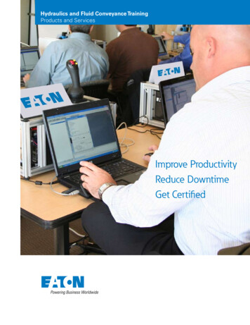
General lnformationShift PatternThe splitter button on shift knob selects one of two available ratios in each lever position except the lower right position.That position automatically will shift between the top two gear ratios.73LOR2184HIR65Low Range109HighRangeWeight530 lbs. / 241 kg for transmission with SAE #1 aluminum clutch housing. Shifting controls, clutch release parts, outputyoke or lubricant are not included.Length28.12” / 714 mm Dimension from face of clutch housing to front bottoming surface of companion flange or yoke.Oil Capacity27 pintsTransmission Center of Gravity LocationWith SAE No. 1 aluminum clutch housing, less shifting controls and output yoke.CoordinateViewed FromMeasured FromDirectionValue - In (mm)LongitudinalLeft sideCase/clutch housing interfaceRearward9.37” (238)VerticalLeft sideMainshaft centerlineUpward.32” (8.2)LateralRearMainshaft centerlineLeft.10” (2.5)Inertia(At Transmission input shaft, in Neutral) .0313 ft-lb-sec2.WarrantyEaton component warranty coverage is listed in the Roadranger Warranty Guide TCWY-0900. This guide details complete component warranty coverage by specific vocation and their respective requirements.To receive warranty coverage all terms and conditions in this manual must be adhered to.Note: Any engine horsepower or torque re-rating beyond component ratings will immediately void the warranty.4SpecificationsThe shift pattern instruction label for this Lightning series transmission is available as Eaton Fuller part number5586257.
General InformationOptionsStandard FeaturesThe following standard features are included on all Lightning series models: Eaton installed reverse switch (part number 4302748) Eaton installed neutral switch (part number 4302749) Eaton installed magnetic drain and magnetic fill plugs and sight glass Right and left countershaft extended splines for rear mounted PTO Right and left side openings for 6 bolt PTO Rear support studs (M16x1.5x34) & hex nuts (M16x1.5x 20) installed by Eaton 16 tooth magnetic speedometer rotor Oil breather Internal transmission cooler fitting (for applicable models) 7/8-14 UNF 2B with o-ring seat Clutch housing with both above and below pull type clutch provisions machined and bushings installed Output bearing cover with electronic speedometer provisions for two drop-in sensors (see section 5 on“Speedometer / Vehicle Speed Sensor” for additional detail)Optional FeaturesThe following options are available and must be specified when ordering a transmission.FeatureOptionsSAE #1 AluminumClutch HousingSAE #1 Aluminum - Nodal engine mountSAE #1 Aluminum - Hydraulic releaseInput Shaft2” 10 splineFront Bearing CoverFor pull type clutchHalf round - 1710, 1760, 1810Output YokeFull round - 1710, 1760, 1810SPL-170, SPL-250, RPL-20, RPL-25Shift ControlsLow, Medium, High TowerLRC, SRC, CRShift KnobWith splitter control button onlyOutput Bearing CoverMagnetic speedometer provisions for two drop-in sensorsMagnetic speedometer provisions for two threaded sensorsSpeedometerSingle output drop-in speed pickupDual output drop-in magnetic speed pickup** Magnetic speed pickup for vehicle use may be supplied by vehicle manufacturer.5
Vehicle InterfaceVehicle Interface - MechanicalDimensional DrawingsComputer Aided Design (CAD) drawings are available. Contact your Eaton Fuller Engineering Representative to discussyour specific needs and required format.Engine RequirementsThis transmission requires an electronically managed engine which is in compliance with SAE J-1939. The transmissionECU will communicate with the engine ECU over the J-1939 communication link. Contact your Eaton Fuller EngineeringRepresentative for engines which are approved with the use of Lightning transmission. See Section 5: Vehicle Interface- Electrical, for wiring installation details.Note: Any engine horsepower or torque re-rating beyond component ratings will immediately void the warranty.SizeMaterialMounting TypeClutch Release TypeSAE #1AluminumStandard Engine MountAbove and below centerline for pull type only,222mm 8.75” release shaft external boss face*SAE #1AluminumNodal Engine Mount,See Nodal Section*Above and below centerline for pull type only,210mm 8.25” release shaft external boss face*SAE #1AluminumStandard Engine MountHydraulic Release* Clutch release yoke pivot shaftsVehicle Interface MechanicalInput ShaftSAE 10 spline 2" (50.8mm) diameter. Pilot bearing diameter - 1.18" (30mm)Master Clutch RequirementsFree-Travel Master ClutchesThis transmission contains backlash or “free-travel” at the input shaft to main drive gear interface. This feature helps toprevent idle gear rattle. Because of this feature, the use of a master clutch containing free travel or pre-damped clutchdiscs is not recommended.Soft Damped Clutch DiscsA soft rate damped clutch (7-spring, VCT, or Rockwell LTD) is required in all drivetrain systems using electronically controlled 10 liter engines and above. Eaton Fuller requires that transmission input torque spikes, due to drivetrain torsionals, must be less than 300 lbs. ft. above the nominal transmission input torque rating for engine speeds above 1000rpm and vehicle road speeds above 20 mph.Vehicle Air Supply RequirementsInlet air pressure required90-130 PSI (620-896 kPA)Air DryerRequiredInlet Port SizeSAE 3/8" - 18 NPTThe inlet port is located on the transmission filter regulator assembly. This filter regulator is located on the left side ofthe transmission in the upper left rear quadrant. See transmission dimension drawings for location details.6
Vehicle InterfaceThe transmission filter regulator assembly regulates the vehicle supply air to 80 PSI (551 kPa).No external air lines are present on this transmission. No external air lines are required for shift knob installation.Vehicle Engine Exhaust Heat Source Clearance EnvelopeThe vehicle engine exhaust heat source can produce high temperatures that must be avoided by the transmission ECU.The exhaust piping, exhaust piping supports, or exhaust gas heat sources must not intrude within the transmission ECUheat source avoidance area. This heat source avoidance area is defined as a 88.9 mm [3.5inch] perimeter around thetransmission ECU. The ambient temperature within this heat source avoidance area must be less than 250 F. See drawing 164-AD sheet 1 & 2 for the dimensional definition.Shift Controls and Mounting LocationThis transmission uses the same shift lever and remote slave control as current product Eaton Fuller transmission.Three shift tower heights are available; Low, Medium, and High. Please note that the shift pattern of the Lightning transmission is tighter than many current models, which may allow the use of a lower tower. Note: Because of the tightershift pattern Eaton does not recommend the use of the high shift tower with Lightning. Remote slave controls available from Eaton Fuller include; Low Remote Control (LRC), Single Rod Control (SRC), Cable Remote (CR). Contact yourEaton Fuller Engineering Representative for additional information or assistance in designing shift controls.The mounting location is the same relative position as current Eaton Fuller transmissions. A standard shift opening andforward shift opening is available. The forward opening moves the low shift tower pivot ball 2.53" (64.4mm) forwardfrom the standard opening location. See dimensional information for location details.Note: See Section 5: Vehicle Interface - Electrical, for information on installation of shift knob.7
Vehicle InterfaceShift Lever DesignTravel CalculationRecommended Shift Lever (Mechanical Advantage) Ratio is 5.5 - 6.5 : 1.(Internal) Shift Lever TravelLightningLightningSuper10LightningRT ModelsLightningFR ModelsRail Movement - Forward Gear Position.43" (11mm)88%88%100%Rail Movement - Rearward Gear Position.43" (11mm)88%88%100%Side Travel - Right (From center position).25" (6.4mm)50%50%100%Side Travel - Left (From center position).25” (6.4mm)50%50%100%Contact your Eaton Representative for applications with lever ratios outside of this range.Shift Lever Jumpout AvoidanceTransmission shift lever jumpout can be an irritating problem for vehicle drivers. Careful truck design can minimize oreliminate this problem. Please refer to Remedies for Shift Lever Jumpout in the appendix of this document.Transmission Oil RequirementsTypeGrade (SAE)Ambient TemperatureUse Eaton Approved E-500 Lubricants only50WAllOil lube tag 4304885 with the above oil use instruction is attached standard to the oil fill plug.Transmission Oil Capacity27 pintsTransmission Oil Level Sight GlassThe transmission is equipped standard with an oil level sight glass. The sight glass allows visual confirmation of correctoil fill in transmission. Proper oil fill is confirmed when the oil level is at the centerline of the sight glass. See dimensional drawings for location.Transmission Cooling RequirementTransmission operating temperature requirements: - Transmissions must not be operated at temperatures above 250 F(120 C).8Vehicle Interface MechanicalUse Eaton approved E-500 lubricants only. Gear oils formulated with EP additive packages must not be used with theLightning transmission and will void the warranty. For additional information on lubricants reference Roadranger Products Lubrication Manual - TCMT-0021.
Vehicle InterfaceInternal Oil CoolerThis transmission will be equipped with an internal oil / water heat exchanger. Vehicle engine coolant is routed to thetransmission where it circulates through a heat exchanging element in the bottom of the transmission case. Heat fromthe transmission oil is absorbed by the circulating engine coolant. The heat exchanger will also warm the transmissionoil at low ambient temperatures. The heat exchanger inlet and outlet are located at the rear of the transmission.In all cases, the coolant flow and coolant temperature must be sufficient to maintain transmission oil temperaturesbelow 250 F (120 C) at worse case operating conditions.It is recommended that the engine manufacturer is consulted in the application and connection of the transmissioninternal heat exchanger to the vehicle’s engine.The engine coolant circuit will require 400 ml of coolant to fill the heat exchanger. Additional coolant volume is in thelines between the engine and transmission.A chart at the end of this section shows additional information of Eaton Transmission cooler applications.WARNING: EP oils destroy heat exchangers. Do not use EP oils in transmissions.Note: The use of EP oils will void the transmission warrantyOEM Guidelines for the Lightning internal coolers:9 Provide 10 GPM coolant @1500 RPM Maximum coolant "In-Cooler" temperature not to exceed 200 F
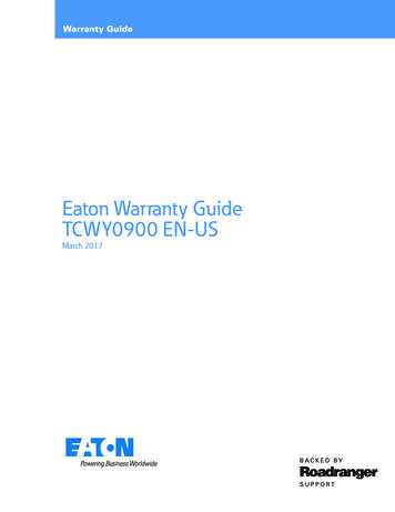
Vehicle InterfaceInternal Transmission Cooler Heat Transfer CapabilityThe following chart shows the Lightning Internal Cooler heat transfer performance over a range of temperature differential conditions with an engine coolant consisting of a 50/50 mix of ethylene glycol and water. The engine coolant thermostat setting was 180 F with 10 gallon per minute coolant flow.Cooler Performance10 GPM 0406080100Delta-T oil /Coolant in FVehicle Interface MechanicalInternal Transmission Cooler Coolant Flow CharacteristicsThe chart below describes the engine coolant flow characteristic for the Lightning Internal transmission Cooler. Thepressure requirements to provide the associated coolant flow can be derived from the characteristic curve.Internal Transmission Cooler FittingsLocation: Cooler ports are located at the rear of the transmission. See dimension drawings for location details.Fitting size and type: 7/8-14 UNF-2B female (with o-ring seat)10
Vehicle InterfaceFastener InformationREMOVAL OF ANY TRANSMISSION CAPSCREWS TO INSTALL BRACKETS OR WIRE HARNESSES IS NOT ALLOWEDAND WILL VOID THE WARRANTY FOR OIL LEAKS. This transmission uses anaerobic gasket sealant. Removal and reinstallation of the clutch housing and any cover capscrews can result in future oil leakage and would void warranty for oilleaks.Eight M8 stud end special screws (with hex nuts provided) are utilized at the rear countershaft bearing covers and PTOcovers at selective locations for use by the vehicle manufacturer in attaching miscellaneous harnesses, hoses etc. (2studs at 2:00 & 4:00 position and 2 at 8:00 & 10:00 position respectively at the RH & LH rear bearing covers; 2 studs atthe centerline positions of each of the 6 bolt PTO LH & RH covers). The special screws clamping the covers to the transmission case must not be loosened when attaching or removing the provided M8 hex nuts. The recommended torquerange for the M8 hex nuts is 27-31 N.m (20-23 Lb.Ft).Four M10x1.5 tapped holes are also provided on the top of the transmission case for exclusive use by the OEM for wiring and hose harness attachment. The fasteners must not exceed thread engagement more than 16.00 mm (.63”)]maximum. The recommended fastener torque range is 54- 61 N.m (40-45Lb.Ft). See dimension drawings for location detail.In addition, lifting eyelets on the top and rear of the transmission can also be used for harness attachment.All capscrews and stud fasteners are metric thread size. Pipe plugs, oil fill plug, and oil drain plug are SAE standard.Lifting EyeletsCast protrusions with machined holes are incorporated into the transmission case. Two eyelets are present on the top ofthe transmission. Two eyelets are present on the rear of the transmission. Eyelet hole diameter is currently 17.8 mm(.70").Rear Transmission SupportTwo M16 mounting studs are provided at the rear of the transmission. These top positioned studs allow attachment of arear transmission support bracket.The centerline of these mounting studs is located 614.8 mm (24.20”) back from mounting surface at front of clutchhousing. This is the same dimension as the current Eaton Fuller transmission.The spacing of the mounting studs is also the same. However, the height of the mounting stud pad is now higher at206.5mm (8.13”) from the transmission centerline versus a 174.8mm (6.88”) dimension for the current product.The standard Eaton 5577504 stud fastening length (34mm stud length – 20mm nut) 14 mm. Thread size: nut attachment end - M16x1.5. Attachment nut: final assembly recommended torque specification 230 – 257 N.m [170 – 190lbs. ft.]. On centerline with spacing of 127 mm (5.00”).WARNING: To avoid damage to the transmission - for installations not utilizing the standard Eaton installedstud above, any alternate transmission housing rear support threaded fastener must meet the following minimum criteria.Fastener thread must be compatible with the transmission tapped hole specification of M16x2.0 – 4H.Transmission housing end of fastener: the length of fastener full threads must be less than 18mm [.71 “].11
Vehicle InterfaceTransmission housing end of fastener: the fastener full thread is to transition to the shank diameter and must provide alimitation to the installed depth of the fastener into the transmission housing tapped hole. Limitation on the installeddepth of the fastener into the transmission tapped hole must be less than 21 mm [.83 “].Speedometer/Vehicle Speed SensorSee“Vehicle Interface - Electrical” on page 14, for installation information.Output SplineTypeInvoluteOutside Diameter69.9 mm (2.75”)Number of teeth54Diametrical pitch20-40Pressure angle in degrees37.5Output YokeThe transmission can be ordered with the output yoke installed by Eaton Corporation, or the yoke can be obtained separated by the OEM and installed by the OEM.The same output yokes used on Eaton Fuller “2” FR Series and “9” RT Series are used on the Lightning Series.Vehicle Interface MechanicalNote: The rear seal surface is not on the output yoke.The following output yoke options are available.SeriesConfigurationYoke Front Face to CrossCenter DimensionEaton Fuller Part Number1710Half Round143 mm (5.63”)55055431710Full Round143 mm (5.63”)55055441760Half Round143 mm (5.63”)55055451760Full Round143 mm (5.63”)55055461810Half Round143 mm (5.63”)55055471810Full Round143 mm (5.63”)5505548RPL25Half Round159 mm (6.26”)5505553SPL170Half Round142 mm (5.60”)5505571SPL250Half Round145 mm (5.71”)550557292NHalf Round143 mm (5.63”)550557812
Vehicle InterfacePTO Interface6 Bolt Side OpeningsTwo 6-bolt PTO openings are provided, one on each side of the transmission. See dimensional drawings for locationdetails.The 6 bolt PTO is driven off a countershaft gear, turning at 63% of engine speed. The side mount PTO must utilize dowelpins to insure proper helical gear alignment with the transmission.Drive Gear: 51 Teeth, 8.38 Diametric Pitch, 17.5º Pressure Angle, 33.1º Right Hand Helix AngleRear Countershaft MountedTwo rear countershaft mounted PTO locations are provided, one on each side of the transmission. See dimensionaldrawings for location details.The rear countershaft mounted PTO is driven off a splined extension of the front countershaft. The drive speed is turning at 63% of engine speed.Drive spline: 31 Teeth, 24 Diametric Pitch, 25º Pressure AngleNote: Reference Eaton Service Manual (TRSM-0580) for PTO installation and sealant requirements.Clutch Housing Nodal Mount InterfaceThe SAE symmetrical nodal mount interface is provided. The nodal mount interface bracket space claim is defined in thefollowing dimensional drawing.13
Vehicle InterfaceVehicle Interface - ElectricalVehicle Electrical RequirementsThe OEM is responsible for designing and providing a wiring harness and connector for the vehicle to transmissionelectrical interface. The OEM is also responsible for providing the J-1939 and J-1587 data link to the transmission.Contact your Eaton Fuller Engineering representative early in the harness design for assistance. This OEM wiring harness design (and the interface with the vehicle and transmission) must be reviewed with Eaton Transmission Engineering prior to production.Top-2 OperationLightning transmissions can be specified with the optional Top2 (T2) feature. T2 is an automated shifting functionbetween the top two transmission gear ratios (9th & 10th gears). The Lightning T2 operation is controlled by the transmission Electronic Control Unit (ECU) compared to other Eaton Super10 Top-2 models which relied on the engine Electronic Control Module (ECM) for T2 control.Engine RequirementsThis transmission requires an electronically managed engine which is in compliance with SAE J- 1939. The transmission ECU will communicate with the engine ECU over the J-1939 communication link. Contact your Eaton Fuller Engineering representative for compatible engines that have been certified for the “4” series transmission.Vehicle Interface ElectricalNote: Any engine horsepower or torque re-rating beyond component ratings will immediately void the warranty.Engine VEP SettingsThe engine VEP settings for Lightning are different compared to Super 10 Top-2. To avoid Engine faults and possibleperformance issues, the following engine settings are required for Lightning:TOP 2 - Disabled or OffTransmission Solenoid(s) - Disabled or OffJ-1939 - EnableDetroit Diesel Optimized Idle SystemThis system requires the addition of a low output / low gain vehicle output speed sensor (VSS) hardwired to the engineECM. In addition to the dedicated VSS the engine configuration setting for 'Transmission ID' must be set to: Transmission ID #0 - Manual This setting allows the engine to recognize the dedicated hardwired VSS for output speed andmaintains required J1939 communication between the transmission and engine.Contact Detroit Diesel for additional informationRoad Speed Governor ConfigurationEngine Road Speed Governor configuration must be configured so that the governed speed settings do not interfere orinhibit the transmission from reaching the automatic Top-2 (9-10) shift point.14
Vehicle InterfaceMinimum Cruise Control Speed SettingsEngine Minimum Cruise Speed Settings may effect the cruise control 'Resume' function if the minimum speed is setabove the engine speed RPM that results at the completion of the automatic Top-2 (9-10) upshift. If this occurs theminimum cruise speed setting must be lowered.Wiring Harness Design NotesAll wires to be 16 Gage GXL per SAE J-1128All wires to be identified.15
Vehicle InterfaceTransmission Electronic Control Unit (ECU) ConnectionECU Connector (Contained on ECU) 18 pi
the following standard features are included on all lightning series models: eaton installed reverse switch (part number 4302748) eaton installed neutral switch (part number 4302749) eaton installed magnetic drain and magnetic fill plugs and sight glass right and left countershaft extended splines for rear mounted pto right and left