Transcription
VERSIONEDITIONCRIMP DATA AND DIESGC32-XD & FLEX & GC96 - POWER CRIMP 707 & SC32 GC16XD-MOBILECRIMP 4-20 DD & PS - POWER STEERING - SWAGING186 - 2020-11-242021
GATESCRIMP DATA DIESGENERALGENERAL INFORMATIONHOSE ASSEMBLY GUIDE . . . . . . . . . . . . . . . . . . . . . . . . . . . . . . . . . . . . . . . . . . 2-7POLAR SEAL I CRIMP DATA. . . . . . . . . . . . . . . . . . . . . . . . . . . . . . . . . . . . . . . . . . . 8POWER STEERING CRIMP DATA. . . . . . . . . . . . . . . . . . . . . . . . . . . . . . . . . . . . . . . 9GATES GLOBAL PART NUMBERING SYSTEM . . . . . . . . . . . . . . . . . . . . . . . . . . . . 10SWAGING INFORMATIONSWAGINGSWAGING PROCEDURES . . . . . . . . . . . . . . . . . . . . . . . . . . . . . . . . . . . . . . . . 11-12TH7 SWAGE DATA . . . . . . . . . . . . . . . . . . . . . . . . . . . . . . . . . . . . . . . . . . . . . . . 13C14 SWAGE DATA . . . . . . . . . . . . . . . . . . . . . . . . . . . . . . . . . . . . . . . . . . . . 15-19GC32-XD & FLEX & GC96 WITH SPACER DIESGC32-XD & FLEX CRIMP DATA. . . . . . . . . . . . . . . . . . . . . . . . . . . . . . . . . . . . 20-42GC32-XD & FLEX LIFEGUARD CRIMP DATA . . . . . . . . . . . . . . . . . . . . . . . . 43-45GC32-XD/FLEXGC96GC96 (WITH SPACER DIES) CRIMP DATA. . . . . . . . . . . . . . . . . . . . . . . . . . . . 46-67CALIBRATION & ADJUSTMENT PROCEDURES. . . . . . . . . . . . . . . . . . . . . . . . 68-72CRIMP DIES AND TOOLING. . . . . . . . . . . . . . . . . . . . . . . . . . . . . . . . . . . . . . . . . . 73CLAMP COLLAR CRIMPING INSTRUCTIONS . . . . . . . . . . . . . . . . . . . . . . . . . . . . 74POWER CRIMP 707 & SC32 POWER CRIMP 707/SC32 CRIMPERS. . . . . . . . . . . . . . . . . . . . . . . . . . . . . . 75PC707/SC32PC 707, 700 SERIES (8 FINGER) DIES CRIMP DATA. . . . . . . . . . . . . . . . . . . 76-98PC707 LIFEGUARD CRIMP DATA . . . . . . . . . . . . . . . . . . . . . . . . . . . . . . . . . 99-100SC32 CRIMP DATA . . . . . . . . . . . . . . . . . . . . . . . . . . . . . . . . . . . . . . . . . . 101-122SC32 LIFEGUARD CRIMP DATA. . . . . . . . . . . . . . . . . . . . . . . . . . . . . . . 123-124CALIBRATION & ADJUSTMENT PROCEDURES. . . . . . . . . . . . . . . . . . . . . 125-126CRIMP DIES AND TOOLING. . . . . . . . . . . . . . . . . . . . . . . . . . . . . . . . . . . . . . . . . 127CLAMP COLLAR CRIMPING INSTRUCTIONS . . . . . . . . . . . . . . . . . . . . . . . . . . . 128GC16XDGC16XDGC16XD CRIMP DATA. . . . . . . . . . . . . . . . . . . . . . . . . . . . . . . . . . . . . . . . 129-133GC16XD CALIBRATION PROCEDURE. . . . . . . . . . . . . . . . . . . . . . . . . . . . 134-135MOBILECRIMP 4-20 DD & PSMOBILECRIMP 4-20 CRIMPERS. . . . . . . . . . . . . . . . . . . . . . . . . . . . . . . . . . . . 136MC 4-20 DD & PSMC 4-20 DD CRIMP DATA. . . . . . . . . . . . . . . . . . . . . . . . . . . . . . . . . . . . . 137-154MC 4-20 PS CRIMP DATA. . . . . . . . . . . . . . . . . . . . . . . . . . . . . . . . . . . . . 155-172CALIBRATION & ADJUSTMENT PROCEDURES. . . . . . . . . . . . . . . . . . . . . . . . . . 173CRIMP TOOLING . . . . . . . . . . . . . . . . . . . . . . . . . . . . . . . . . . . . . . . . . . . . . . . . . 174CLAMP COLLAR CRIMPING INSTRUCTIONS . . . . . . . . . . . . . . . . . . . . . . . . . . . 175POWER STEERINGPOWER STEERING MALE FLARELESS ASSEMBLY INSTRUCTIONSPOWER STEERING ASSEMBLY INSTRUCTIONS. . . . . . . . . . . . . . . . . . . . 176-177NOTE: CRIMP DATA FOR OMNICRIMP 21, POWER CRIMP 3000B &POWER CRIMP 2001 IS LOCATED IN ECRIMP. DOWNLOAD THE ECRIMPAPP OR GO TO WWW.GATES.COM/ECRIMP.DOWNLOAD THE ECRIMP APP OR GO TO WWW.GATES.COM/ECRIMP1
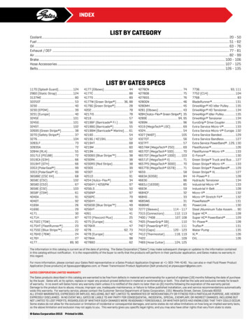
GATESHOSE ASSEMBLY GUIDEGENERALHOSE ASSEMBLYGUIDESWAGINGWear the proper personal protection equipment when workingwith fabrication equipment to make assemblies. To find thehose use the STAMPED process to determine which product isneeded, then identify the terminations of the existing assemblyby their physical characteristics and dimensions.GC32-XD/FLEXGC96Once the hose has been determined select the appropriatecoupling by looking through the crimp data to find what stemand ferrule types may be used. Use the stem and ferrule with thetermination information to determine the best coupling to use.CCCCCCDEFGHIFIGURE 1From left to right: Measurement of D) flange, E) straight male, F) US spec., G)International spec., H) FFOR and I) bent (elbow) couplings.DETERMINE THE CUT LENGTH OF THE HOSETo determine the cut length of the hose, first find the overall lengthof the hose assembly. The point at which the ends of the assemblyare measured will depend on the construction of the couplings.PC707/SC32GC16XDAll flanges are measured from the center point of the flangeface, Figure 1D. All straight male couplings are measured fromthe seal face, Figure 1E. Straight female couplings with SAE,JIC (FJX), NPSM (FPX), JIS and Komatsu specifications aremeasured from the farthest point which the nut will extend,Figure 1F. Straight female couplings with DIN, BSP, GAZspecifications are measured from the face of the seal, Figure1G. Straight Flat Face O-ring seal (FFOR) couplings are alwaysmeasured from the face of the seal, Figure 1H. All bent andblock couplings (male and female) are measured from the pointat which the center line of the coupling intersects the seal face,Figure 1I.MC 4-20 DD & PSOnce the overall length of the assembly is determined the cutlength of the hose will be the overall length of the assemblyminus the “C” length of each coupling, as shown in Figure 2. “C”lengths are available in the Gates Hydraulic catalog.CUTTING THE HOSEPOWER STEERINGOnce the cut length of the hose has been determined it is timeto cut the hose section to length. Rubber hydraulic hoses shouldbe cut with a hose cutting saw, equipped with a scalloped,serrated or abrasive blade.2FIGURE 2A hose assembly.A serrated blade will produce the cleanest cut, but should onlybe used for cutting hose with fabric, textile, wire braid or spiralwire reinforcement. Usually serrated blades should not beused for cutting helical wire embedded hose. If the hose sawis equipped with a blade cooling mechanism, then a serratedblade may be used to cut spiral wire hose. Serrated saw bladesmay be flipped and also re-sharpened to extend their life.An abrasive composite blade is capable of cutting all types ofhose, but will product much more smoke and dust than serratedblades and leave more contamination in the hose that will needto be removed so it does not get into the hydraulic system onceinstalled. Abrasive composite blades will wear down over timeand must be replaced when it cannot cut fully through a hose.Use the hose bending fixtures on the hose cutting saw in orderto prevent blade binding and they will help achieve straightconsistent cuts. To meet SAE and ISO standards the hose cutmust be within 5 of perpendicular, on 1” hose this is less than3/32”, Figure 3.PTFE and thermoplastic hydraulic hoses may be cut cleanly witha shear. Once the cut is made the tube must be deburred usinga sharp knife.DOWNLOAD THE ECRIMP APP OR GO TO WWW.GATES.COM/ECRIMP
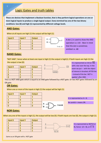
GATESHOSE ASSEMBLY GUIDESWAGINGGENERALBuffing is the removal of some hose cover material while stillleaving material covering the hose reinforcement. This is doneboth for wire and non-wire reinforced hose construction, andwhen necessary for coupling installation. A grinding wheel isused for buffing for consistency and to help prevent damage tothe reinforcement.FIGURE 3Up to 300 mm, included3Over 300 mm through 450 mm, included5Over 450 mm through 900 mm, included7Over 900 mm 1%(1)FIGURE 5Measured to nearest whole milimeter.PC707/SC32(1)Picture of a skived hose end.COUPLING INSTALLATIONSAE J517 assembly length tolerance.When cutting any hose it is important to understand the amountof variation in length which is appropriate. The SAE provides theguidelines shown in Figure 4. Generally it is best to have a smallamount of extra hose in an assembly, however even a smallamount of extra length can be very problematic especially forshort hoses.SKIVING AND BUFFINGSkiving or buffing should only be done as recommended in thecrimp specifications, most Gates products no longer requireskiving or buffing for installation.Skiving is the removal of the hose cover down to thereinforcement, Figure 5. Skiving may be done with a wireabrasion wheel or a hand skiving tool. Careful attentionshould be paid to ensure that skive length is correct and thereinforcement has not been damaged in the skiving process.DOWNLOAD THE ECRIMP APP OR GO TO WWW.GATES.COM/ECRIMPOnce the hose has been completely prepared dry fit all of thecouplings to ensure that the assembly length and orientation iscorrect in the final assembly.GC16XDFIGURE 4When two bent couplings are used on an assembly orientationis critical, per SAE specifications the couplings must be within 3 of desired. In order to achieve this begin by orienting thecoupling on the far end of the hose vertically downward, thenmeasure the orientation clockwise from this position for thenear end. Once positioned place a witness mark on the hoseand coupling. For hydraulic hoses the layline makes an idealway to confirm the proper orientation of the couplings.Bear in mind that during the crimping process the assemblywill grow slightly due to compression of the ferrule and hose.For assemblies which are very critical in length, comparemeasurements before and after crimping on end of the assemblyso that compensation may be made for the change in length.3MC 4-20 DD & PSTOLERANCE(PLUS OR MINUS) MMPOWER STEERINGLENGTHGC32-XD/FLEXGC96Hose cut length tolerance
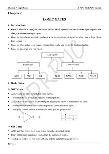
GATESHOSE ASSEMBLY GUIDEFULL LENGTH CRIMP ONE-PIECE COUPLINGS (G, P,GSM, MGS)GENERALWhen installing 1 piece couplings it is recommended that thehose is marked with the insertion depth from each cut end. Thisway there is a mark to verify the coupling has been fully insertedinto the hose.SWAGINGIncorrectCorrectThese types of couplings require a full length crimp, shown inFigure 7. In order to form the full length crimp the edge of thecoupling should be inserted into the die approximately 1/8”past the die edge. This will ensure that the entire ferrule iscrimped, without a bubble near one end.FIGURE 6GC32-XD/FLEXGC96Correct crimper usage.CRIMPINGThere are several different crimping procedures described,depending on the coupling which is to be applied. No matterwhat style of crimp is used the same safety rules apply.PC707/SC32 Assemblies must be fabricated only from NEW(Unused) Gates hose and couplings. Always consult the most current crimp data availableto check the crimp specifications and machinesettings. GC16XDMC 4-20 DD & PSPOWER STEERING4Load the recommended die set into the crimper.Properly lubricate the crimper dies, but do notlubricate the bore of the die. Always wear safety glasses Keep hands away from moving parts of the crimper. For any questions consult the crimper operationmanual or Gates technical support. All settings are approximate! Variation due totolerances and wear may exist, always measure thefinished crimp diameter.CRIMPFULLLENGTHFIGURE 7Full Length Crimp.FULL LENGTH CRIMP TWO-PIECE COUPLINGS (GS,GSP, PC, B & S STAINLESS STEEL)CRIMPWhen installing 2 pieceFULLcouplings (with separate stem andLENGTHferrule) place the ferrule onto the cut hose then insert the steminto the hose. If stem insertion is very difficult the serrationsmay be lubricated with light oil, and if necessary the couplingrestrained in the jaws of a vice. Be sure that the hose is fullyinserted onto the stem by moving the ferrule and visuallyinspecting. When crimped the ferrule must be latched into thestem shoulder, see figure 9.These types of couplings require a full length crimp, see Figure8. In order to form the full length crimp the edge of the couplingshould be inserted into the die approximately 1/8” past the dieedge. This will ensure that the entire ferrule is crimped, withouta bubble near one end. Before making the crimp be sure ferruleis engaged in the stem latching collar.DOWNLOAD THE ECRIMP APP OR GO TO WWW.GATES.COM/ECRIMP
GATESHOSE ASSEMBLY GUIDEMEGACRIMP INSERTION TOOLGENERALThis tool offers an easy way to confirm the right insertion depthfor MegaCrimp, see Figure 10. To use, simply insert the hoseinto its proper slot indicated by dash size, push it all the way in,check for squareCRIMPcut (maximum allowable angle of cut is fiveFULLLENGTHdegrees), then mark the insertion depth on the hose.BellMeasureCrimp tion LengthCRIMPFULLLENGTHGLX coupling crimpBUBBLE CRIMP ONE-PIECE COUPLING (GL)FIGURE 9Full length crimpProper 2 - piece coupling assemblyWhen installing 1 piece couplings it is recommended that thehose is marked with the insertion depth from each cut end. Thisway there is a mark to verify the coupling has been fully insertedinto the hose.PC707/SC32FIGURE 8GC16XDThe GL coupling is only intended for low pressure service,despite this it is still critical that the correct crimp outsidediameter and tail length are achieved in order to make a leakfree connection. The tolerance on the tail length of the crimpis 0.100 inches. In order to achieve this tolerance: line thecoupling up with the ridges in the appropriate die, see Figures12 and 13. Be sure the die fingers are all the way forward andlocked in place before crimping.FIGURE 10When forming a GLX crimp only the tail end of the coupling iscrimped. DO NOT crimp the full length of the ferrule. In order toachieve the proper crimp length, mark this point onto the ferrule,and only insert the ferrule in the dies up to the mark, bear in mindthe tolerance on the crimp length is 0.030 inches. See Figure 11.DOWNLOAD THE ECRIMP APP OR GO TO WWW.GATES.COM/ECRIMPMC 4-20 DD & PSPARTIAL LENGTH CRIMP ONE-PIECE COUPLING (GLX)When installing 1 piece couplings it is recommended that thehose is marked with the insertion depth from each cut end. Thisway there is a mark to verify the coupling has been fully insertedinto the hose.Align hose end of uncrimpedferrule flush with internalridge on dies.Crimp DiesCrimp Diameter(Front Crimp)For 81, 82and 83 diesTail LengthMeasure Crimp Here(Front Crimp)POWER STEERINGInsertion toolGC32-XD/FLEXGC96FIGURE 11FIGURE 122 band bubble crimp (dies 81, 82, and 83)5
GATESHOSE ASSEMBLY GUIDEGENERALAIR CONDITIONING COUPLINGS (ACA)When crimping couplings for use with refrigerants be sure tofully insert the hose into the coupling, a small hole is located onthe ferrule for visual confirmation of the hose insertion. No skiveor buff is needed or recommended for Polarseal hose and ACAcouplings. During crimping center the bands of the crimping dieon the ferrule as shown in Figure 15.SWAGINGFIGURE 133 band bubble crimp (dies 84 and 85)GC32-XD/FLEXGC96BUBBLE CRIMP ONE-PIECE COUPLING (GLP)When installing 1 piece couplings it is recommended that thehose is marked with the insertion depth from each cut end. Thisway there is a mark to verify the coupling has been fully insertedinto the hose.PC707/SC32In order to achieve the correct crimp be sure to align thecoupling in the die as shown in Figure 14.Align staked end of the ferrule(fitting end) flush with the die face.FIGURE 15ACA coupling alignmentGC16XDFor Die Series:71, 72, 73, 74 & 75Measure Crimp HereMC 4-20 DD & PSFIGURE 14GLP alignment in crimper dies (die 71, 72, 73, 74, and 75)POWER STEERING* See Adjustment Procedures and Footnotes at the end of GC32-XD / GC96 section.6DOWNLOAD THE ECRIMP APP OR GO TO WWW.GATES.COM/ECRIMP
GATESHOSE ASSEMBLY GUIDECRIMPER ADJUSTMENTShould the actual crimp diameter not be within the tolerancespecified in the crimp data charts, check the calibration of thecrimper. If the calibration is correct a slight adjustment of thecrimper setting may be necessary.GENERALWhen measuring a crimp position the caliper at the center ofthe crimp length, or the appropriate band (as indicated in thecrimping diagrams), as shown in Figure 19. This is becausesome taper may exist between the ends of the crimp.To find the right adjustment to the setting, refer to your specificcrimper’s operating manual. When the setting has been calculatedand your new crimp is within the specified tolerance, make sure torecord your new approximate setting in the space provided in thismanual under “User’s actual setting” for future reference.SWAGINGMEASURING THE CRIMPFIGURE 19Correct position to measure the crimp diameter along the length of the ferruleThe crimp diameter must always be measured on the flats180 around the coupling, NOT on the protruding ridges,as shown in Figure 20. For -8 and larger couplings place thecoupling against the rear of the caliper jaw and use the wideflat area to measure. For -4 and -6 couplings use Notched endof the Gates Stainless Steel Digital Calipers, place the smallflats at the end of the jaw against the flats on the coupling.Always measure the crimp diameter from the depressed flatarea of the ferrule; DO NOT place the notches over protrudingridges of the coupling.Common methods of cleaning the hose assembly includeblowing through the assembly with shop air or a much moreeffective method is the use of a shuttle. The Gates MegaCleansystem uses foam projectiles to remove debris from hoses andassemblies. For particularly difficult jobs multiple projectilesmay be fired from each end or a solvent such as water oralcohol may be applied to the pellets.PC707/SC32One Piece CouplingsGC16XDTwo Piece CouplingsAfter the assembly has been successfully crimped it should becleaned in order to prevent contamination of the system onto whichit is being installed. This should be done with all assemblies sinceparticulates from the cutting or crimping process and other debrismay have entered the hose during fabrication.GC32-XD/FLEXGC96CLEANING THE HOSEPOWER STEERINGMC 4-20 DD & PSMeasuring -8 and larger couplings Measuring -4 and -6 couplingsFIGURE 20Measuring the crimp outside diameter on the flats between the ribsDOWNLOAD THE ECRIMP APP OR GO TO WWW.GATES.COM/ECRIMP7
GATESPOLAR SEAL I CRIMP DATAGENERALPOLAR SEAL ICRIMP DATAHOSESTEMCRIMPCRIMPERDESCRIPTIONSIZE(IN)WORKING PRESSUREPSIDASH SIZE1/16"TYPELENGTH 0.03"OD 0.01"CRIMPERDIE 1.455DASH .50USERSETTINGGC16XDMC 4-20 DD & PSPOWER STEERING* See Adjustment Procedures and Footnotes at the end of GC32-XD / GC96 section.8DOWNLOAD THE ECRIMP APP OR GO TO WWW.GATES.COM/ECRIMP
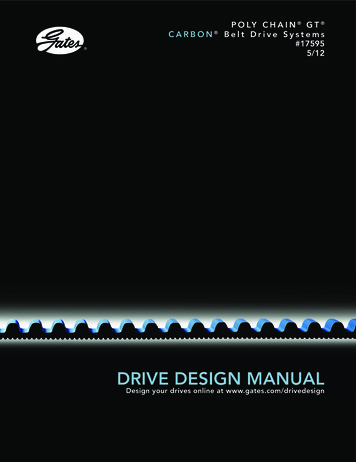
GATESPOWER STEERINGGENERALPOWER STEERINGCOUPLINGS E 17Diagram showing PS coupling crimp detailsFIGURE 16The MFA is a means for attaching the coupling to metal tubingfrom the existing power steering assembly. At least 1 inchof straight (unbent) metal tubing must be available for theattachment of the MFA. Cutoff (or “C”) dimensions for the PScouplings are given in Figure 16.Cutoff lengths for PS couplingsThe correct insertion depth for the PS coupling is 1.25 0.030inches. Be sure to mark this on the hose prior to couplingapplication to ensure full insertion depth has been achieved.Prior to crimping the coupling also ensure that the bottom ofthe stem hex is aligned with the top of the die set, as shownin Figure 17. When the crimp is complete inspect to thedimensions shown in Figure 18.MC 4-20 DD & PSFIGURE 18PC707/SC32CUTOFF (INCHES)6PS-4MFAGC16XDCOUPLINGSWAGINGPower steering couplings come are designed for PS188 powersteering hose and come with MFA (male flareless adapter)terminations.Alignment of PS coupling in diePOWER STEERING CRIMP 0.375015006PSTAILCRIMPERTYPELENGTH 0.03"OD 0.01"LENGTH 0.1"CRIMPERDIE 0.25MC420PSMC44Blue 07/SC32744/PS1.75WORK. PRESS. DASH SIZEPSI1/16”DOWNLOAD THE ECRIMP APP OR GO TO WWW.GATES.COM/ECRIMPUSERSETTINGPOWER STEERINGHOSEDASHSIZE1/16"9
GATESGATES GLOBAL PART NUMBERING SYSTEMGENERALGATES GLOBAL PARTNUMBERING SYSTEMSWAGINGSTEM TYPESERIES STEM STYLESB-SSG17 - Stainless Steel Braid CouplingsS-SSG18 - Stainless Steel Spiral CouplingsG8KG19 - G8K CouplingsGSG20 - GlobalSpiralMGSG21 - GlobalSpiral One Piece Couplings for MC4-20 CrimperGC32-XD/FLEXGC96GSPG22 - GlobalSpiral PlusGSMG23 - GlobalSpiral Max (-32) Pressure CouplingsGSMG24 - GlobalSpiral Max Pressure CouplingsGG25 - MegaCrimp CouplingsGLG43 - GL CouplingsGLXG44 - GLX CouplingsACAG45 - PolarSeal CouplingsPSG50 - Power Steering CouplingsPC707/SC32GC16XDMC 4-20 DD & PSPOWER STEERING10DOWNLOAD THE ECRIMP APP OR GO TO WWW.GATES.COM/ECRIMP
GATESSWAGING PROCEDURESGENERALSWAGINGPROCEDURESSWAGINGMark hose for proper insertion depth into coupling. See GatesHose Swage Data chart for insertion depth. Use a lightweightoil to lubricate the inside diameter of hose. Place the couplinghex into a vise and insert hose to insertion depth.GC32-XD/FLEXGC96The following are the basic swage procedures. For specificinstructions for your crimper or swager, please refer to theappropriate operator’s manual. Swaging can be accomplishedwith either the Gates HS-1 Hand Swager (Product No. 74831000) or with the Swager Conversion Kit for the Power Crimp 707 (Product No. 7480-0040).1. See Swage Data chart to select specific pusher and die foreach coupling and hose combination to be swaged. TheSwage Tooling page contains specific part/product numberinformation for each pusher and die.2. Insert the correct die and pusher into the swaging machine.PC707/SC323. Lubricate inner bore surfaces of dies with a thin film oflightweight oil.4. Feed hose assembly through the dies and hold hose andcoupling into the pusher. Start the swage.POWER STEERINGMC 4-20 DD & PSGC16XD5. Swage is complete when pusher bottoms out on dies.DOWNLOAD THE ECRIMP APP OR GO TO WWW.GATES.COM/ECRIMP11
SWAGE TOOLINGGATESGENERALSWAGE TOOLINGSWAGINGGC32-XD/FLEXGC96PC707/SC32SWAGER CONVERSION KIT FOR THE POWERCRIMP 707 CRIMPERProduct No. 7480-0040GC16XDMC 4-20 DD & PSPOWER STEERING12DOWNLOAD THE ECRIMP APP OR GO TO WWW.GATES.COM/ECRIMP
GATESTH7 SWAGE DATAGENERALGATES HOSESWAGE DATATH7 AND TH7NC THERMOPLASTIC HOSESSWAGINGUse PCTS couplings with TH7 and TH7NC thermoplastic hoses.PUSHERS AND DIES FOR PCTS COUPLINGS ANDTH7 HOSEPCTS SWAGE PUSHERSPCTS SWAGE DIES1GATESSYNFLEXPARKERDESCRIPTIONPRODUCT CTS-3FJXFINISHED SWAGEOD /- .010 001303MC 4-20 DD & PSASSEMBLYINSERTIONLENGTH /-.03 (IN)POWER TS SWAGE PUSHERSDenotes dual seatDOWNLOAD THE ECRIMP APP OR GO TO WWW.GATES.COM/ECRIMP13
GATESSWAGING GC16XDMC 4-20 DD & PSPOWER STEERINGTHIS PAGE INTENTIONALLYLEFT BLANK.14DOWNLOAD THE ECRIMP APP OR GO TO WWW.GATES.COM/ECRIMP
GATESC14 SWAGE DATAGENERALSWAGE TOOLINGC14 PTFE HOSENOTE: Always use the proper personal protection equipment when making assemblies.STEP 1 – HOSE CUTTINGSWAGINGAfter determining hose cut length by deducting for fittings, cut hose with shear. No tapingor deburring is necessary, since shearing the hose holds braid flaring to a minimum.STEP 2 – HOSE INSERTIONGC32-XD/FLEXGC96Place ferrule in hose insertion die holder with tapered end down. Place insertion diesin die holder so that taper will guide hose into ferrule. Push hose through dies witha slight twisting motion until seated; pull hose out. Insertion dies will fall out as youremove hose. Check end of ferrule for full insertion.STEP 3 – HOSE EXPANSION AND STEM INSERTIONPC707/SC32Next, select proper size expansion rod and secure in a vise. Push hose over bead severaltimes to expand tube. Place stem (and nut if used) on rod. Push hose onto stem untilstem is completely inserted - no gaps between shoulder on stem and ferrule. If a gapexists, ferrule must be twisted and pushed forward until gap is eliminated.STEP 4 – SWAGINGSelect proper size dies and pusher and install them in the Gates HS-1 hand swager(Product No. 7483-1000) or swager conversion kit for the PC707.GC16XDIf using the PC707 with conversion kit installed, remove actuator rod to swage.Lubricate bore of die set with light oil. Using one hand to hold assembly so fittingremains seated in pusher, start swage. Swage is complete when pusher bottoms outon dies. When swaging is complete, reinstall actuator rod into crimp position.When swage is complete, ferrule outside diameter must be within the recommendedfinished swage outside diameter.POWER STEERINGMC 4-20 DD & PSIf ferrule outside diameter is not within tolerance, check for die wear and replaceif necessary.1Denotes dual seatDOWNLOAD THE ECRIMP APP OR GO TO WWW.GATES.COM/ECRIMP15
GATESC14 SWAGE DATAGENERALSWAGE TOOLINGPUSHERS AND DIES FOR C14 HOSE AND COUPLINGSC14 HOSE INSERTION DIESC14 SWAGE PUSHERSC14 HOSE EXPANDERSSWAGINGGC32-XD/FLEXGC96C14 SWAGE DIESPC707/SC32GC16XDMC 4-20 DD & PSPOWER STEERING16DOWNLOAD THE ECRIMP APP OR GO TO WWW.GATES.COM/ECRIMP
GATESC14 SWAGE DATAGENERALGATES HOSE SWAGE DATAC14 PTFEUse C14 couplings with C14 hose.Gates pushers and dies MUST BE USED to swage Gates C14 hose with Gates C14 couplings.1Product -5C146C14-6MIX907753-2040-5-H
crimp data and dies gc32-xd & flex & gc96 - power crimp 707 & sc32 - gc16xd-mobilecrimp 4-20 dd & ps - power steering - swaging version 186 - 2020-11-24 edition 2021