Transcription
Introduction to LogixPro - LabPurposeThis is a self-paced lab that will introduce the student to the LogixPro PLC Simulator software. In this lab thestudent will9 install LogixPro9 create a new project9 select a simulator panel9 enter several rungs of ladder logic including branches9 simulate going online with the PLC and running a program9 learn how the simulator I/O interacts with the program code9 discover some of the quarks to avoid when using LogixProPrerequisites Hands-on experience with Windows 2000, Windows XP or Windows Vista Successfully completed the Introduction to RSLogix 500 labCompleting this lab teaches the student how to:1.2.3.4.5.6.7.8.start the LogixPro softwarechange simulationschange the switch type in the I/O simulator panelenter rungs of ladder logicdownload a project file to the simulated PLCrun the PLC programadjust scan timeunderstand I/O interaction, XIC/XIO contacts, OTE coilsInstructions1. Carefully read all the instructions.2. Read the entire instruction before performing the step. Do not press any keys on the keyboard or click anybuttons on the mouse until the entire step is read and understood.3. Instructions are marked with a check box. When a step has been completed, place a check mark in the boxprovided.4. If you lose your place or have any problems contact your instructor for assistance.Icons Used in this LabThis icon designates a quark in the LogixPro software. A quark is defined as afunction in the LogixPro simulator that functions differently than the RSLogixsoftware.This icon designates a difference in the way LogixPro works compared to RSLogix.LOGIXPRO SOFTWARELogixPro softwareLogixPro is a PLC simulator that is particularly geared toward Rockwell’s RSLogix 500 software. There isno need for any PLC hardware when using the simulator. The keyed edition of LogixPro, that is part of thecourse materials, provides animated process simulations, including an I/O simulator with changeable switchtypes, output indicators, thumbwheel switches and a BCD digital readout. Several process animations arealso included and we will be working with several of them in future homework labs.1 of 8
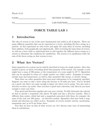
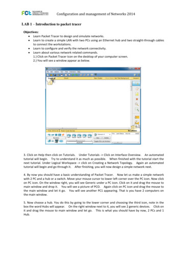
Installing LogixPro1. Place the LogixPro CD in the CD-ROM drive.2. The installation should start automatically.3. Read all the instruction screens and install LogixPro.If the install does not start automatically:1.2.3.4.5.6.Make sure that the LogixPro CD in the CD-ROM drive.Click Start – Run.From the Run dialog box click Browse, then browse to the CD-ROM drive.Locate the file; install.exe on the CD and double click on it.The installation should start.Read all the instruction screens and install LogixPro.Running LogixPro Place the LogixPro CD in the CD-ROM drive. Wait for the CD to spin-up. The LogixPro software willnot open unless the CD-ROM drive has spun-up and thekey on the CD has been read. When the key has been reada small splash screen will momentarily appear as shown in Figure 1.Figure 1 After the small splash screen appears LogixPro can be started. Launch the program by double clicking on theLogixPro shortcut on your desktop or by clicking Start – Programs – TheLearningPit – LogixPro – LogixPro. Maximize the LogixPro window.Updating LogixPro Software If this is the first time you are running the LogixPro software, the software will need to be updated. Before updating the LogixPro software, make sure you areconnected to the Internet. The update will be performed overthe Internet. Drop down the Help menu and select Online – Check foravailableLogixPro updates as shown in Figure 2. Follow the prompts to update the LogixPro software.Figure 2The LogixPro Interface The LogixPro interface is very similar to the RSLogix 500 interface, so now that you have successfullycompleted the introduction to RSLogix 500 lab, you should quickly be able to become comfortable in theLogixPro environment. Figure 3 shows the LogixPro environment after the software is initially started. Note the similarities and differences to RSLogix 500. The first obvious difference is that there is asimulation where the project window should be and that there is an animated help wizard on the screen. Ifyou would like to hide the animated help wizard, right click on him and select Hide. The Online/Offline tool box has no functionality except for the Online/Offline dropdown box and thisdropdown box is not really needed. The menu bar is different because there are some functions in the RSLogix 500 software that are notneeded in the LogixPro software, and some options in the LogixPro software that are needed for it tofunction properly. One such menu is the Simulations menu. The instruction tool bar is the same as RSLogix 500 except that not all the instructions are available inLogixPro and there is an additional button in the upper right corner. This button is called the toggle button2 of 8
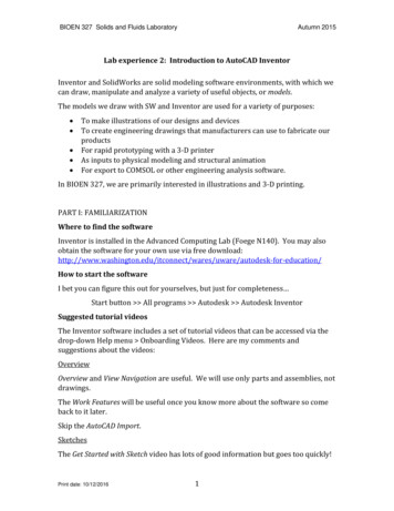
and will toggle the PLC simulator from offline to online mode. Scan through the instruction tabs andobserve what is and is not available.Menu bar, note theSimulations menuThe projectwindow is replacedwith the simulationgraphicsThe instruction toolbar is the same asRSLogix 500 withthe exception of anadded button in theupper right cornerof the tool barFigure 3 Click on the Simulations menu to drop down the menu as shown in Figure 4. Note the available simulations.These simulations will only function with the keyed version of the LogixPro software.Feel free to explore the simulations. These simulations have no function until you write PLC ladder logic tocontrol them. When you are finished exploring the available simulations select the I/O Simulator, then dragthe window pane divider to view the I/O Simulator as shown in Figure 5. Dragging the window pane dividerin LogixPro is a-bit odd and does not always act like a normalWindows application. Have patience if at first you don’t succeed. The switches wired to the input modules can be closed by moving themouse pointer over the switch until the pointer changes to a hand with apointing finger. Click the mouse button and the status of the switch willchange from open to close or close to open. The type and status of the switch can be changed by right clicking onthe switch. The switch type can be changed to a normally openpushbutton, a normally closed pushbutton, a normally open limit switcha normally closed limit switch or the normally open toggle switch thatis currently shown. The color of the output indicators can also be changed by right clickingon an indicator and selecting a color from the pop-up menu.Figure 43 of 8
Figure 5 Size the Simulator window pane to show only the first four discrete I/O modules. The thumbwheelswitches and the BCD digital display will not be needed until later in the course. To display the project window, click the close button ‘X’ of the simulator window. The close button willtoggle the window between project view and simulator view. Not all functions are available in the projectwindow. Explore what functions and options are available. User defined data files are not available inLogixPro and you do not have to configure the processor, the I/O or the communications.Enter a Rung of Ladder Logic Make the ladder editor window the active window. The very first rung of a LogixPro ladder diagram can not be dragged into the editor and dropped.To insert the first blank rung simply click the Insert Rung button in the tool bar and the new rung willappear. After the first rung is inserted, other rungs can be dragged into the editor window just like inRSLogix 500. Drag an Examine if Closed (XIC) instruction onto the rung. Drag an Output Energize (OTE) instruction onto the rung. Note that there is no target near the rightpower rail as in RSLogix 500. Simply drop the OTE at the target to the right of the XIC and it will beplaced against the right power rail. To add addresses to the instructions, double click the instruction and type the address into the inputfield. Address the XIC instruction to: I:1/0 and the OTE instruction to O:2/0.4 of 8
Instruction descriptions cannot be added but symbols can. To enter a symbol, right click on theinstruction and select Edit Symbol from the pop-up menu. Type a descriptive symbol in the input field. Atotal of 28-characters are allowed to be entered in this field. Assign any symbol you want to theinstructions. When you are finished your screen it should look similar to the one shown in Figure 6.Figure 6 Click the Toggle button in the upper right corner of the Instruction Tool Bar. The Instruction Tool Barwill change to display the PLC Panel as shown in Figure 7.Instruction Tool BarToggle buttonPLC PanelFigure 7 In order to run a program it must be downloaded to the PLC. Click the Download button in the PLCPanel. The screen will momentarily flicker to simulate that the program is being downloaded.5 of 8
Click the RUN radio button. This will place the PLC in the run mode. Click on the switch addressed to I:1/0 in the I/O Simulator. The switch should close and the indicatorlight addressed to O:2/0 should light. In the ladder logic editor, instead of the instructions being highlighted to show power flow, theaddresses will glow yellow to show power flow.Inserting a Branch Before inserting a branch, insert another blank rung above the current rung. Change to PGM mode by clicking on the PGM radio button. Click the toggle button to switch to the instruction tool bar. Change the switch connected to I:1/9 to a normally open push button and the switch connected to I:1/10to a normally closed push button.Add this rung. It isthe start of aStart/Stop circuitNote the switchtype and status.I:1/9 is a normallyopen push buttonand I:1/10 is anormally closedpush buttonFigure 8 Place two XIC and one OTE instruction on the rung. Assign the addresses: I:1/10, I:1/9 and O:4/5. Thescreen should look similar to Figure 8. A branch will be inserted around I:1/9. Inserting a branch in LogixPro is slightly different thaninserting a branch in RSLogix 500. In LogixPro the branch handle cannot be dragged to where the branchshould end; instead, insert the branch and then drag the instructions onto and into the branch. Insert abranch as shown in Figure 9. Drag the instruction addressed to I:1/9 into the branch.Figure 10 depicts the Start PB being dragged into the branch and Figure 11 show the Start PB in thebranch. Insert an XIC instruction on the branch and address it to O:4/5.6 of 8
Figure 9Figure 10 The ladder logic should now look like Figure 11. Click the toggle button to return to the PLC Panel.Figure 11 Download the program to the PLC.7 of 8
Change to RUN mode and run the program. Clicking on the Start PB should energize O:4/5 and clickingon the Stop PB should de-energize O:4/5. The circuit should work exactly as if being attached to a realPLC.Try It On Your OwnExperiment with the simulator on your own. Get as creative as you like and have fun.Some Quarks About LogixProLogixPro has some quarks that the user needs to be aware of. Following is a list of some known quarksTwo or more coils can be placed in series and the program will still run. This is not allowed in RSLogix500 and should not be done in LogixPro.A rung that is not complete will not affect the operation of the LogixPro program. An example would bea rung with an XIC instruction on it but no output coil. This situation would cause an error in RSLogix 500.Remove all unfinished or un-necessary rungs from the LogixPro program just as a matter of aesthetics.Timers and counters can be placed in series and the program will still run. When two or more timers areplaced in series and the rung is true, all series timers will be running. When two or more counters are placedin series and the rung is transitioned from false to true, the accumulator of all series counters will eitherincrement or decrement depending upon if the counter is a CTU or CTD. Timers and counters are outputinstructions and should not be put in series. Always place output instructions in parallel using branches.Timer and counter preset and accumulators are 32-bit unsigned positive values and will not overflow orunderflow as they do in RSLogix 500. The values of the preset and the accumulator can be 0 to 231 – 1 or 0 to2,147,483,647. When this maximum value is achieved the counter will simply stop counting.Math instructions perform 32-bit math. The arithmetic status bits do not function and the math register isnot available. Be careful when using the math instructions because things like divide by zero will not create afault or generate an error.If you close LogixPro without saving your work, your work will be lost. LogixPro will not prompt youto save any unsaved work.If LogixPro is closed and then restarted you might get a message asking for the CD Key and that the trialperiod has expired. If this happens, close LogixPro, open the CD-ROM drive that contains the LogixPro CDand then close it again. Wait for the CD to spin-up and the LogixPro startup splash screen to appear as inFigure 1, and then start LogixPro.XIC and XIO instructions that reference a normally closed switch do not always show the proper statuswhen the program is first switched from PRM mode RUN mode. To correct the problem simply operate thenormally closed switch from closed to open and back to closed. This should resolve the improper instructionstatus.8 of 8
1 of 8 Introduction to LogixPro - Lab Purpose This is a self-paced lab that will introduce the student to the LogixPro PLC Simulator software. In this lab the