Transcription
CHRISTIANA HOSPITAL2 0 1 0 P R OJ E C TNEWARK, DEThesis ProposalJoseph G. SharkeyStructural OptionFaculty Consultant: Dr. Memari
Table of ContentsExecutive Summary ----------------------------- 2Introduction ------------------------------------- 3Codes ------------------------------------------- 4Current Structural System ------------------FoundationColumnsFloor SystemLateral Force Resisting SystemRoof System555578Gravity Loading ---------------------------------- 9Problem Statement ------------------------------ 10Problem Solution --------------------------------- 10Solution Method --------------------------------- 11Breadth Topics ----------------------------------- 12Tasks & Tools ------------------------------------- 12Time Table ----------------------------------------- 14Joseph SharkeyThesis Proposal1
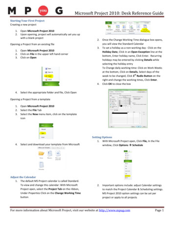
Executive SummaryThe Christiana Hospital project is a 299,000 square foot addition to theChristiana Medical Campus. This expansion, designed by architects atWilmot/Sanz, will expand the hospital’s clinical capabilities along with addinga new medical education center capable of providing this teaching hospitalwith the latest techniques and learning tools. Structurally the building hasbeen designed essentiallyinto two separate buildings.These two buildings consistof a three story educationwingusingsteelconstruction and an eightstory clinical tower .This paper is designed topropose an alternativedesign for the Christiana Hospital. The design will consist of dividing themain clinical tower into separate structures coming together at an expansionjoint to decrease the torsional effects on the lateral force resisting systemwhile still maintaining the building’s functionality and architectural appeal.Secondly the current 9½” thick two-way concrete floor system will beredesigned using post-tensioning in an attempt to decrease the slab depth.Designing the building in this manner will require a redesign of the shearwalls along with the complete redesign of the floor system. This newstructure will be compared to the original design regarding efficiency andconstructability.Along with the redesign of the Christiana Hospital’s structural system twobreadth topics will be discussed focusing in fields of constructionmanagement and mechanical engineering.Regarding constructionmanagement, the impact of the redesign on overall project cost and theconstruction schedule will be addressed. Concerning the mechanicalbreadth, air in the Christiana Hospital is currently cooled using chilled waterprovided by an outside source. I propose to research and design a chiller thatwill be capable of creating this chilled water on site and compare its cost andfunctionality to the current system.Joseph SharkeyThesis Proposal2
IntroductionThe Christiana Hospital project is a 299,000 square foot addition to theChristiana Medical Campus.The addition, designed by architects atWilmot/Sanz and the structural engineers at Cagley & Assoc., will expand thefacilities and capabilities of the hospital along with advancing this teachinghospital’s educational abilities with a new medical education center. This projectconsists of two separate types of framing. The majority of the building, an eightstory hospital tower, is designed using reinforced concrete while the adjacentconference wing is a three story steel structure.This report is designed to propose an alternate design to the hospital’s structurealong with two separate breadth topics. The main structural issue proposed issectioning the building by creating an expansion joint at grid line 66 (refer toFigure 3 on page 11). This design will hopefully reduce the torsional effects onthe shear walls and allow them to be smaller in size. Secondly a post tensionfloor slab will be designed and compared to the current 9½” two-way flat slabwith 5½” drops around the columns. This slab will most likely allow for a smallerslab depth allowing a higher ceiling height or extra room in the ceiling for MEP.Joseph SharkeyThesis Proposal3
C o d esCodes Used for Original Design International Building Code – 2000 ASCE 7-98, American Society of Civil Engineers – Minimum DesignLoads for Buildings and Other Structures ACI 318-99, American Concrete Institute – Building CodeRequirements for Structural Concrete ACI Manual of Concrete Practice – Parts 1 through 5 – 1997 Manual of Standard Practice – Concrete Reinforcing Steel Institute AISC Manual of Steel Construction – Allowable Stress Design, NinthEd., 1989 AISC Manual of Steel Construction – Volume II Connections – ASDNinth Ed./LRFD First Ed. AISC Detailing for Steel Construction American Welding Society – Structural Welding Code ANSI/AWSD1.1-96 Steel Deck Institute – Design Manual for Floor Decks and RoofDecks Drift Criterion – h/400Codes Used for Thesis Design International Building Code – 2003 ETABS Model – International Building Code – 2000 ETABS Model – ASCE7-98 Wind Loads – ASCE7-02 AISC Manual of Steel Construction – Load and Resistance FactorDesign, Third Ed., 2005 Drift Criterion – h/400Joseph SharkeyThesis Proposal4
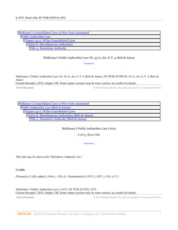
Current Structural SystemFoundation:The building consists of two separate types of foundations. In the concretetower area the building rests on a 42” thick mat foundation. This mat isreinforced with #9’s at 12” o.c. each way, top and bottom, with additionalreinforcing added where needed.In the area of the conference wing, steel columns rest on concrete spreadfootings. These footings range in size from 4’x4’x 15” deep up to 16’x16’x 48”deep. The allowable soil bearing pressure for this site is 4000 psf.ApplicationsConcrete Strengths (f’c)Footings4000 psiMat Foundation6000 psiGrade Beams4000 psiSlab-On-Grade3500 psiColumns:In the tower area a majority of the columns are 24”x24” reinforced concretecolumns with only a few occurrences of 12”x24” columns. At the eighth floornearly all the concrete columns stop and off of them W8 steel columns areposted. The 3 story conference wing is composed of W10 and W12 steelcolumns.ApplicationsMaterialSteel ColumnsConcrete Columns(Below Third Floor)Concrete Columns(Above Third Floor)ASTM A992, Grade 504000 psi5000 psiFloor System:Throughout the tower, spans are accomplished using 9½” thick two-way flatslabs with typical 5½” drops or shear caps at each column. Reinforcementfor the slabs varies throughout the building.The conference area uses a completely separate type of floor system. Heresteel girders span between columns in one direction while beams, spanning inJoseph SharkeyThesis Proposal5
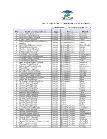
the opposite direction, frame into the girders. This steel framework works incomposite action with the floor slab placed on top. The slab is constructed of3¼” lightweight concrete over a 2” deep x 18 gage galvanized compositemetal deck. The slab is then reinforced with 6x6-W2.1xW2.1 WWF. Thebulk of the spans vary anywhere from 20 to 40 feet. Although, running acrossthe middle, is a large 63 foot span made possible using W30x90 beams andthe composite action.Steel WingConcrete TowerJoseph SharkeyThesis Proposal6
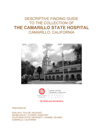
Lateral Force Resisting System:The lateral forces acting on thebuilding are resisted differentlyin the two areas of the building.In the concrete portion of thebuilding, lateral forces areresisted by reinforced concreteshear walls which run the entireheight of the building until theyare replaced by concentricallybraced frames at the eighthfloor (Figure 1). These shearwalls are placed in specificareas to also oppose the torsioneffect that the lateral loadsplace on the building due to itsL-shape.In the conference wing lateralloads are taken care of with theuse of concentrically bracedframes (Figure 2).Theseframes are constructed usingrectangular HSS steel. Thisframing is field welded togusset plates. These gussetplates are attached in thefabrication shop, by means of aweld, to select beams.Figure 1 Shear WallsFigure 2 Concentrically Braced FramesJoseph SharkeyThesis Proposal7
Roof System:The framing of the roof is done entirely with steel and metal decking. Thedecking used is a 1½” deep, wide rib, 20 gage galvanized metal deck. On topof the decking is a one hour fire rated roof construction. This consists of a 45mill fully adhered roofing membrane on tapered insulation on 5/8” exteriorgypsum board. The metal decking is also sprayed with a fireproofing at thesoffits.Joseph SharkeyThesis Proposal8
Gravity LoadingFloor Live LoadsOccupancy or UseUniform Live Load (psf)Assembly Space100Typical Hospital Floor60Corridor80Mechanical Rooms150Stair100Roof15Partition20Floor Dead LoadsOccupancy or UseDead LoadReinforced Concrete150 pcfSteel MembersVariesFloor Superimposed15 psfRoof Superimposed15 psfItemSnow LoadingValueGround Snow Load (Pg)25 psfExposure CategoryBRoof ExposurePartially ExposedExposure Factor (Ce)1.0Thermal Factor (Ct)1.0Occupancy CategoryIVImportance Factor (Is)Flat-Roof Snow Load1.2Pf 0.7CeCtIsPgJoseph SharkeyThesis Proposal21 psf9
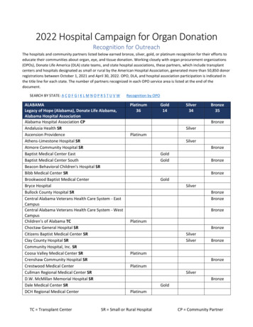
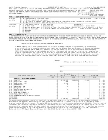
Problem StatementThrough the analysis of the gravity and wind force resisting systems done intechnical assignments numbers 1 and 2 it is clear that the system chosen bythe design teams is currently the most efficient possible. The use of a 9½”two-way flat slab with 5½” drops around the columns allows for a shallowfloor system and makes the unique geometries and column layouts possible.The current shear walls and their layouts are also very efficient in keeping thedeflection of the building low and resisting the torsional forces caused by thebuildings geometry.Because the current system performs so well it is a difficult job to try andimprove or make beneficial changes to the building. With this in mind I willattempt to redesign the floor system checking to see if it is possible to createa shallower floor thickness along with sectioning the building to reduce thetorsional forces on the shear walls.Problem SolutionFloor System:The proposed floor system is one which utilizes the strength capacity of posttensioning. This floor system will potentially create a shallower floor depthalong with the possibility of creating larger spans by reducing the amount ofcolumns required. Column sizes may also be capable of being decreased dueto the reduced self weight of the new floor system.Lateral Force Resisting System:To reduce the torsional loading effects created by the building’s geometry onthe shear walls sectioning the building with the use of an expansion joint isproposed. This expansion joint will be investigated further but currently thebest location for this joint appears to be on column line 66 (Figure 3). Thiswill essentially separate the main medical tower of the building into twoseparate buildings acting independently of one another. By this being doneshear walls will potentially be capable of being designed smaller in size whichcould result in a cost savings.Joseph SharkeyThesis Proposal10
Figure 3 Expansion joint located on grid line 66Solution MethodFloor System:The design of the post-tensioned slab will be completed in accordance withACI 318-05 chapter 18 with help from a computer model created using RAMConcept. The slab will be designed using the loadings stated on page 9 ofthis paper. After obtaining this new slab, column load takedowns will beperformed to acquire the new vertical loads imposed on the columns andchecked using a computer model created in ETabs. With these new loads thecolumns will then be redesigned.Lateral Force Resisting System:With the building now being divided into two separate structures, shear wallswill be reviewed by adding, subtracting, or moving them to new locations thatwill serve the new design more effectively. With these shear walls now inplace both seismic and wind loads will be placed on the building using handJoseph SharkeyThesis Proposal11
calculated loads in accordance with ASCE7-02 and distributed to the shearwalls with the help of an ETabs model. Finally the shear walls will bedesigned for the new loads imposed on them.Breadth TopicsTopic 1:The first topic which will be covered is in the field of constructionmanagement. With these new designed being implemented I will make acomparison between the costs and schedules of the actual design to myproposed design. This information will then be used to determine whether ornot the proposed design is beneficial or detrimental in comparison to theactual design.Topic 2:The second topic to be covered will be in the field of mechanical engineering.Currently the Christiana Hospital creates its cool air with the use of chilledwater that is supplied by an outside source. I propose to design a chiller forthe building that will be capable of creating the chilled water for coolingpurposes in house. With this design a cost comparison will be performed tosee if money can actually be saved by having a chiller on site or if pumping inchilled water, as is currently done, is more cost effective.Tasks & ToolsPhase I: Post-tensioned Floor System AnalysisTask 1: Determine LoadingTask 2: Design SlabA) Determine minimum slab thicknessB) Find applied momentsC) Check capacity of slabD) Check deflectionsPhase II: Redesign ColumnsTask 1: Determine loadingTask 2: Take into consideration any columns that may not be requiredJoseph SharkeyThesis Proposal12
Task 3: Design columns in accordance with ACI with help from theprogram PCA ColumnPhase III:Task 1:Task 2:Task 3:Task 4:Redesign Shear Walls for new Expansion Joint DesignDetermine most efficient locations for shear wallsFind wind and seismic loads on building using ASCE7-02Distribute loads to shear walls using ETabs modelDesign WallsPhase IV: Breadth StudiesTask 1: Construction ManagementA) Compare costs and schedules of the actual design to theproposed design.Task 2: Mechanical EngineeringA) Design ChillerB) Compare costs to run chiller as opposed to pumping inchilled water from outside sourceJoseph SharkeyThesis Proposal13
Time TableWeek 1Week 2Week 3Week 4Week 5Week 6Week 71/14 - 1/201/21 – 1/271/28 – 2/32/4 – 2/102/11–2/172/18–2/242/25 – 3/3Research post-tensioningCreate RAM ConceptModelDesign post-tensioningfloorNew column DesignsDetermine shear walllocationsCreate ETabs ModelDetermine wind/seismicloadingDistribute lat. forces anddesign shear wallsBreadth 1- ConstructionManagementBreadth 2 - MechanicalEngineeringCreate final reportCreate final presentationPresent to facultyResearch post-tensioningCreate RAM ConceptModelDesign post-tensioningfloorNew column DesignsDetermine shear walllocationsCreate ETabs ModelDetermine wind/seismicloadingDistribute lat. forces anddesign shear wallsBreadth 1- ConstructionManagementBreadth 2 - MechanicalEngineeringCreate final reportCreate final presentationPresent to facultyJoseph SharkeyThesis ProposalWeek 8Week 9Week 10Week 11Week 12Week 13Week 143/4 - 3/103/11 – 3/173/18 – 3/243/25 – 3/314/1–4/74/8–4/144/15 – 4/21SPRINGBREAK14
Thesis Proposal Executive Summary The Christiana Hospital project is a 299,000 square foot addition to the Christiana Medical Campus. This expansion, designed by architects at Wilmot/Sanz, will expand the hospital's clinical capabilities along with adding a new medical education center capable of providing this teaching hospital