Transcription
Journal of Rehabilitation in Civil Engineering 1-2 (2013) 80-89journal homepage: http://civiljournal.semnan.ac.ir/Static and Dynamic Analyses of Micropiles toReinforce the High Railway Embankments on LooseBedsM. Esmaeili 1 , M. Gharouni Nik 1 and F. Khayyer 2*1. Assistant Professor, School of Railway Engineering, Iran University of Science and Technology, 16846 Iran,Tehran, Narmak.2. M.Sc., School of Railway Engineering, Iran University of Science and Technology, 16846 Iran, Tehran,Narmak.* Corresponding author: f k@engineer.comARTICLE INFOArticle history:Received: 17 November 2012Accepted: 26 May 2013Keywords:MicropilesNumerical modelingEmbankmentLoose bedsBearing capacityABSTRACTConstruction of railway embankments on loose beds withoutusing any methods of soil improvement (e.g. stone columnsin silt and clay beds, deep soil mixing method, jet groutingand also using micropiles individually or in groups form)leads toreduction of embankment slope gradient, whichsignificantly increases the volume of soil operation.Generally, micropile as a reinforcing element with the alproperties of soil, is a proper methodology for the aim ofimproving loose earth with low bearing capacity andintensive settlement characteristics. This paper exploresnumerical models of non-reinforced and reinforced railwayembankments (with the height of 10 to 25 m) rested on loosebeds that simulated and analyzed by SLIDE software. Itshould be considered that in order to reinforce theembankments using different arrangements of micropiles. Inaddition, the non-reinforced and reinforced embankmentswere analyzed against different load combinations thatconsist of railway operational load, permanent weight of therail line and intense earthquake load. It should be mentionedthat LM71 standard load was used as operational load duringthe simulations. The main purpose of this paper is finding theoptimum arrangement of micropiles to reinforce the highrailway embankments on loose beds. Therefore, accordingnumerical analyses procedure, it was resulted that the use ofmicropiles exactly between toe and 1/3 to 1/2 length of theembankment slope is the optimal way to reinforce theembankments on loose beds.
M. Esmaeili et al./ Journal of Rehabilitation in Civil Engineering 1-2 (2013) 80-891. IntroductionGenerally, geotechnical engineers are facingtwo options in dealing with problematic soilssuch as loose soils with low bearing capacityor high consolidation, liquefied soils,remoulded soils, and so on:A. Use of load bearing elements in the soil totransfer the applied loads to a deeper, morecompetent or stable stratum;B. Improvement and modification of physicaland mechanical properties of soil mass.Each of these solutions has its ownspecifications, which have been greatlydeveloped over many years. Some of theinnovative techniques have a nature combinedof both methods (with the advantages of both),among which the use of micropilesindividually or reticulated (in groups form) canbe noted [1].Micropiles refer to the lightly reinforced andgrouted piles with a diameter smaller than 30cm. Micropile not only acts as a load bearingelement resistant against applied loads, butalso improves the mechanical properties of thesurrounding soil because of the cementgrouting [2].Before using micropile as a way to reinforcethe high embankments in the site conditions,the numerical and experimental investigationsare necessary to prove the efficiency of thismethod. Accordingly, several numericalstudies have been conducted by engineerscommunity during the recent years thatexpress the applicability of micropiles in thisway. For instance, Cantoni and Collotta [3]investigated the reticulated micropilesstructures to reinforce the slopes againstsliding. Dam stabilization with micropiles wasstudied by Haider et al. [4]. In another work,Bruce et al. [5] designed a micropile wall tostabilize a railway embankment in theenvironment of Flac-2D software. In addition,Wang et al. [6] analyzed micropile foundationin subgrade by using finite element method.Finally, Howe [7] examined the efficiency of81micropiles for slope stabilization by usingfinite element and equilibrium point software.Accordance with the above, this paper isprepared to numerically examine themicropiles in a software environment, too. It isremarkable that the study is about theembankment with height of 10 to 25 m.It is noteworthy that in this paper, SLIDEversion 5.0 has been used to design micropilesfor reinforcing embankment slope against thesliding. By using this 2D slope stabilityanalysis software can calculate the safetyfactors for circular slope failure surfaces,based on a number of widely used limitequilibrium techniques including BishopMethod. In addition, some specifications areconsidered to select this software, which are asfollows: combination of an attractive, easy touse CAD based graphical interface with a widerange of modelling and data interpretationoptions, the similarity between the simulatedenvironment and real conditions, simplicity ofthe software environment, high capability ofmodelling the embankment, micropiles againstthe applied loads [8].The main purpose of this design is todetermine the most appropriate location ofmicropile embankment slope in order to beused in experimental modelling. The mostcritical material and geometrical conditions forthe embankment have been considered toincrease the efficiency of this investigation.Considering this issue and the realisticconditions established for this embankment,the following have been considered for theintended simulation: the dead load resultingfrom weight of the rail line pavement, the liveload resulting from the operational loads ofrail line (that's calculated based on LM71standard load), and finally the earthquake loadfor earthquake-prone areas [9].
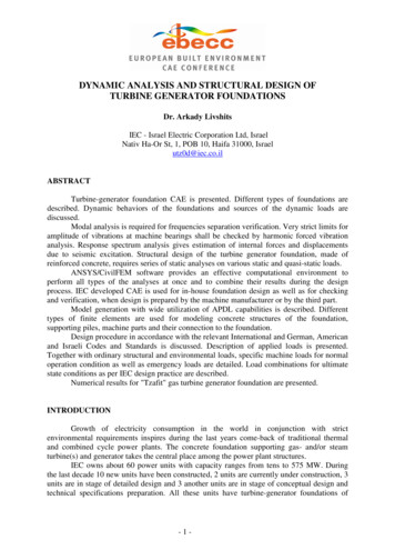
82M. Esmaeili et al./ Journal of Rehabilitation in Civil Engineering 1-2 (2013) 80-892. Inputs of SLIDE Software forDesigning MicropilesAs mentioned before, to examine theefficiency of micropiles to reinforce theembankments and determine the optimumarrangement of them, the numerical models ofnon-reinforced and reinforced embankmentssimulated by SLIDE software that theAnalysis MethodBishop simplifiedTable 1. Analysis information of SLIDE softwareMaximum number ofNumber of slicesToleranceSurface Typeiterations250.00550Circular2.1. Determining the properties of bed andembankmentConsidering the prevalent use of highembankments for making the infrastructure ofrailway lines, moreover the stability problemsof them against the static and dynamic loadscause that the range of embankments heightselected between 10 to 25 for SLIDEsimulations. It's to be noted that the beddimensions determined based on a logicalrelative to the embankment dimensions (Table2).Height of theembankment (m)1520significant analysis information are given inTable 1. It's to be noted that SLIDE is a 2Dslope stability program for evaluating thestability of circular or non-circular failuresurfaces in soil or rock slopes. SLIDE is verysimple to use, and yet complex models can becreated and analyzed quickly and easily.External loading, groundwater and support canall be modelled in a variety of ways.Radiusincrement10According to UIC719-R code [10], thegradient of embankment slope is typicallyconsidered to be 1 to 3, 1 to 2 and 2 to 3.Obviously, if the slope gradient increases, thevolume of the soil operation in theconstruction of embankment is reduced.Consequently, because of the use of micropilefor creating economic balance, maximumslope gradient has been considered in thesimulation of embankment. In order tooptimize the paper size just shown the figuresof embankments with the height of 15 and 20m, as the pictorial outputs of SLIDE analyses(Figs 1 and 2).Table 2. The dimensions of bed and embankmentLength of theLength of theLength of theembankmentembankmentDepth of bed (m)bed sides (m)slope (m)crest (m)27156153620620Fig 1. Dimensions of a 15-m embankment simulated by SLIDE softwareDepth of themodified partof the bed (m)22
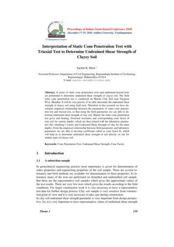
83M. Esmaeili et al./ Journal of Rehabilitation in Civil Engineering 1-2 (2013) 80-89Fig 2. Dimensions of a 20-m embankment simulated by SLIDE softwareGiven that the most critical conditions havebeen considered, the soil of bed was chosenfrom loose soils with low bearing capacity.Accordingly, the bed material was selectedfrom the SP sand [11]. Also to model theembankment and an upper 2-m layer of thebed, the properties of SC material were used(according to the soil characteristics of theimplemented embankments in the Iranianrailways after 1978) [12]. The selectedmaterial properties are given in Table 3.Table 3. The material properties of bed and embankmentPropertiesType of soilEmbankment soilBed soilStrength TypeγSoil (kN/m3)c (kPa)φ (degree)Mohr-CoulombMohr-Coulomb201820130282.2. Loading the embankmentδ 1 β α γ(2)The vertical loads that were assumed tosimulate the embankment in the SLIDEenvironment are based on permanent weight ofrail line and railway operational load. Also, toapply the earthquake load, a seismic loadcoefficient (horizontal) was assumed to beequal to 0.3 . It's to be noted that the unitweight of ballast has been supposed to be 1.9t/m3. The vertical overheads are calculatedaccording to Eq. (1).α 0.04 [V/100]2(3)Q P / (L B)(1)QL (4 37.5) / (6.4 6) 3.91 (t.m/m2)QD1 (0.3 1.9 3.65) / 6 0.347 (t.m/m2)QD2 (0.15 1.9 6) / 6 0.285 (t.m/m2)It is noteworthy that the amount of operationalload determined depending on the amount ofaxial force which is variable between 20 to37.5 ton. Furthermore, the effect of impactload is applied for vertical efforts by using theEq. (2), (3), (4) and (5).β 0.2γ γ0 . α . β(4)γ0 0.1 0.17 [V/100]2(5)V 200 (Km/h) δ 1 0.16 0.2 0.025 1.385 1.3Finally, the values of load combinations tosimulate the embankment by SLIDE, arecalculated according to the Eq. (6), (7) and (8).load combination Case 1 QD1 QD2 δ.(QD1 (6)QD2) 0.632 0.243 0.875 (t.m/m2)load combination Case 2 QL QD1 QD2 δ.(QL QD1 QD2) 0.632 3.91 1.5 5.41 (t.m/m2)(7)load combination Case 3 QE QD1 QD2 δ.(QD1 QD2)(8)It's to be noted that according to UIC719-Rcode (1994), the allowable safety factors of
84M. Esmaeili et al./ Journal of Rehabilitation in Civil Engineering 1-2 (2013) 80-89embankmentstabilizationforloadcombinations Case 1, 2 and 3 are 1.5, 1.3 and1.1, respectively.2.3. DeterminingmicropilesthepropertiesofThe material properties of micropilesWater cement ratio and the characteristics ofreinforcing steel can be considered as the mostElasticity modulus ofcement grout (MPa)31000important material properties of micropiles.According to FHWA guidelines (2000), watercement ratio was considered between 0.45 to0.6. In addition, the elasticity modulus ofcement grout and reinforcing steel (for steelbar and casing pipe) were assumed to be equalto 31 and 200 Gpa (standard wrought steel),respectively (Table 4).Table 4. The material properties of micropilesCompressive strength ofWater cement ratiocement grout (MPa)34.50.45 to 0.6Recent research suggests, however, that incertain conditions and for certain micropilearrangements, the micropiles are principally,directly, and locally subjected to bending andshearing forces, specifically near the slidingsurface [13]. Accordingly, to simulate themicropiles in the environment of SLIDEsoftware, the amount of allowable shearstrength of micropile is used, that has beenconsidered to be 0.55 fˊc πR2, where fˊc isthe compressive strength of the cement grout.In addition, an equivalent steel section ofmicropiles was used (Eq. (9)) to calculate theElasticity modulus ofreinforcing wire (MPa)200000shear strength according to the Eq. (10)(Figure 4) (ACI 318 [14]).ESteel I1 EGrout I2 ESteel I3 EGrout I4 EGrout I(9)200 5.15 31 31038.04 200 8717.59 31 267035.38 31 (πR4/ 4)R 25.92 (cm)FS 0.55 fˊc πR²(10)FS 0.55 34500 0.211 21.555 (kN)Fig 3. Representation of LM71 standard load (Ehteshami et al., 2004)Fig 4. Cross-section of the micropile with a diameter of 15 cm
M. Esmaeili et al./ Journal of Rehabilitation in Civil Engineering 1-2 (2013) 80-8985D. Number of micropiles: total number ofmicropiles increased as trial and error untilachieving the allowable safety factor ofembankment slope stability; andE. Micropiles spacing: it was also reduced astrial and error until achieving the allowablesafety factor of embankment slope stability.It should be considered that this item wasvariable in two orientations, lateral andlongitudinal spacing that the first is thedistance between distributed micropilesalong the length of embankment slope, andthe second is the distance betweenmicropiles along the length of embankment(FHWA, 2000).It's to be noted that by using therecommendations of UIC719-R code (1994)about the location of micropiles in theembankment slope can reduce the steps ofdesigning in trial and error method.Accordingly, in this paper all the micropilesarrangements were based on the bothrecommended case of UIC719-R code (1994)(Figure 5).The geometrical parameters of micropilesDetermining the geometrical parameters ofmicropiles are important to simulate reinforcedembankment which were assumed as Table 5.A. Length of micropiles: to reduce theoperation of trial and error method in orderto obtain optimum arrangement ofmicropiles, constant values have beenconsidered for the length of micropiles,which assumed to be 10 to 25 m for the 10to 25-m embankments, respectively;B. Angle of micropiles relative to the verticalaxis: the angle of micropiles has beenselected between 0 to 30 degree relative tothe vertical axis. According to the deepfailure of embankment slope and theselected length of micropiles, the angleswere selected such a way that themicropiles cross the sliding surfacecertainly;C. Diameter of micropiles: to reduce thenumber of micropiles for savings infinancial costs of construction process, thediameter was considered to be themaximum dimension, equal to 30 cm;Table 5. The geometric parameters of micropiles arrangementParametersLMP (m)θ(degree)DMP (cm)NSectionSLateral(m)SLongitudinal(m)No. 1150 to 3030400.5No. 21503046.750.5No. 315 to 2503046.750.5No. 4No. 5No. 6No. 715151515000153030303033444.54.53310.50.50.5No. 8200 to 3030600.5No. 920030660.5No. 1020 to 30030660.5No. 11No. 12No. 13No. rrangement numberLength of theslope thatreinforcedToe of theembankmentslopeWhole thelengthWhole thelength1/3length1/3length1/3length1/3lengthToe of theembankmentslopeWhole thelengthWhole thelength1/2length1/2length1/2length1/2 length
86M. Esmaeili et al./ Journal of Rehabilitation in Civil Engineering 1-2 (2013) 80-89Fig 5. Recommendations of UIC719-R code (1994) about the location of micropiles in the embankmentslope3. Designing the micropiles toreinforcethehighrailwayembankments on loose bedsFirst, the embankment stability was examinedin a non-reinforced condition, then it would bereinforced with different arrangement ofmicropiles; and the analysis procedurecontinued as a trial and error method, untilachieving the allowable safety factor ofembankment slope stability.- Lateral loads like earthquake load are moreeffective for creating sliding on theembankments slope; and- Lateral loads are more effective on the highembankments.non-reinforcedB. The embankments wasn't even close to themoment of failure against the loadcombinations Case 1 and 2 (Figures 6(a)and 7(a)), while deep sliding occurs in theembankments slope against the loadcombination Case 3 (Figures 6(b) and 7(b));andResults of the analysis procedure on nonreinforced embankments with the height of 10to 25 m are as follows:C. The main reason of deep sliding in theembankments slope was the lateralmovement of layers of loose beds (Figures6 and 7).3.1.AnalysingembankmentstheA. As was expected, the load combinationCase 3 was more critical than the loadcombinations Case 1 and 2, the reasons forwhich are as follows :According to the Figures 6 and 7, theembankments failure just appeared againstthe load combination Case 3. Accordingly,all the followed numerical simulationswould be done based on this loadcombination.Fig 6. (a) The stability of non-reinforced embankment with the height of 15 m against the load combinationCase 2 (FS 1.54 1. 3), and (b) its failure against the load combination Case 3 (FS 1.02 1. 1)
87M. Esmaeili et al./ Journal of Rehabilitation in Civil Engineering 1-2 (2013) 80-89Fig 7. (a) The stability of non-reinforced embankment with the height of 20 m against the load combinationCase 2 (FS 1. 46 1. 3), and (b) its failure against the load combination Case 3 (FS 0. 93 1. 1)3.2. Analysis of embankments reinforcedwith micropilesTo examine the efficiency of micropiles toreinforce the embankments, 10 to 25-membankments reinforced with differentarrangements of micropiles were studied; andthe output results of the research are given inTable 6.Results of numerical analyses on theembankments with the height of 10 to 17 m:A. Using the micropiles exactly in the toeof 10 to 17-m embankments slope wasnot very effective in order to prevent thesliding due to the high altitude ofembankments; and failure still occurredin the upper part of the embankments.B. The distribution of micropiles along thewhole length of slope for theembankments with the height of 10 to17 m, was effective only by using themicropiles with very long and nonstandard length in order to cross thesliding surface.C. The micropiles distribution between thetoe and 1/3 length of slope was the mosteffective and appropriate location toreinforce the slope of embankmentswith the height of 10 to 17 m.Results of numerical analyses on theembankments with the height of 17 to 25 m:A. Using the micropiles exactly in the toeof 17 to 25-m embankments slope evenwith long length couldn't stabilize theslope.B. The distribution of micropiles along thewhole length of slope for theembankments with the height of 17 to25 m, was effective only by using themicropiles with very long and nonstandard length in order to cross thesliding surface.C. The micropiles distribution between thetoe and 1/2 length of slope is the mosteffective and appropriate location toreinforce the slope of embankmentswith the height of 17 to 25 m.According to the above mentioned, it'sobserved that the optimum arrangements ofmicropiles to reinforce the embankments withthe height of 15 and 20 m are arrangementsNo. 6 and 13, respectively (Figure 8 and 9).Table 6. The results of analyses procedure for the reinforced embankmentsNumber 7No.8No.9No.10No.11No.12No.13No.14Safety 81.101.10
88M. Esmaeili et al./ Journal of Rehabilitation in Civil Engineering 1-2 (2013) 80-89Fig 8. The results of analysis procedure on 15-membankment reinforced with micropilesarrangement No. 6 (FS 1. 1)4. ConclusionIn this paper, high railway embankmentswhich are rested on loose beds, have beensimulated and analyzed against the standardload combinations by SLIDE software todetermine the optimum arrangement ofmicropiles.To this end, in the first step, the non-reinforcedhigh embankments on loose beds weresimulated in order to investigate the slopestability, then the embankments reinforcedwith different arrangements of micropiles toexamine the efficiency of this methodology.Finally, the optimum arrangement ofmicropiles was determined.Based on the research, it was resulted that thebest location of micropiles to reinforce thehigh railway embankments is between the toeand middle of embankments slope; moreover,by using the maximum diameter of micropilescan reduce the number of them to minimizethe financial costs of construction process. Itshould be considered that the optimumarrangement of micropiles has beendetermined in a trial and error method, and toreduce the steps of this method can assume theamounts of some geometrical parameters suchas length and angle, constantly. Finally, theamounts of other parameters obtained duringthe software analysis.Fig. 9. The results of analysis procedure on 20-membankment reinforced with micropilesarrangement No. 3 (FS 1. 1)Based on the results obtained, the use ofmicropiles exactly between the toe and 1/3 to1/2 length of embankment slope is the optimalway to reinforce the embankments on loosebeds by modifying the physical andmechanical properties of bed soil, sewing itsloose layers together, and transferring theapplied load to a deeper, more competent orstable stratum.NotationB: width of loading area (width of embankmentcrest) (m);c: cohesion of soil (kpa);DMP: micropile diameter (cm);EGrout: elasticity modulus of cement grout (Gpa);ESteel: elasticity modulus of reinforcing steel (Gpa);FS: shear strength (KN);fˊc: compressive strength of the cement grout(MPa);I: moment of inertia of the equivalent steel section(cm4);I1: moment of inertia of area 1 (cm4);I2: moment of inertia of area 2 (cm4);I3: moment of inertia of area 3 (cm4);I4: moment of inertia of area 4 (cm4);L: length of loading area (length of embankmentcrest) (m);LMP: micropile length (m);N: number of micropiles;NSection: number of micropiles in embankmentsection;P: operational load or permanent weight of rail line(t.m) ;
M. Esmaeili et al./ Journal of Rehabilitation in Civil Engineering 1-2 (2013) 80-89Q: applied distributed constant load on theembankment crest (orientation: vertical) (t.m/m2);QD1: ballast overhead (t.m/m2);QD2: sub-ballast overhead (t.m/m2);QE: earthquake load (seismic load coefficient 0.3);QL: distributed operational load (based on LM71standard load Fig. 3.) (t.m/m2);R: radius of the equivalent steel section(cm);SLateral: lateral micropile spacing (transversedistance between micropiles) (m);SLongitudinal: longitudinal micropile spacing (m);V: velocity (Km/h);α, β, γ : velocity factors (non-dimensional);δ: impact factor (non-dimensional);φ: angle of internal friction (degree);γSoil: soil density (kN/m2); andθ: angle of micropile relative to the vertical axis(degree).REFERENCES[1] Esmaeili, M., Gharouni Nik, M., Khayyer, F.(2010),“Improvementtherailwayembankments with micropiles”. M.S. thesis,School of Railway Engineering of IranUniversity of Science and Technology,Tehran, pp. 50-100.[2] FHWA, (2000). “Micropile design andconstruction guidelines”. Report No.FHWA-SA-97-070,UnitedStatesDepartment of Transportation, pp. 31-200.[3] Cantoni, R., Collotta, T., Ghionna, V.N.,Moratti, P.V. (1989). “Design method forreticulated micropiles structures in slidingslopes”. Ground Engng, Elsevier Ltd., Vol.22, No. 4, pp. 41-47.[4] Haider, T.F., Byle, M.J., Horvath, R.E. (2004).“Dam stabilization with micropiles”.Proceedings of Sessions of Geo‐Denver2000, ASCE, Denver, Colorado.[5] Bruce, J., Ruel, M., Janes, M., Ansari, N.(2004). “Design and construction of amicropile wall to stabilize a railwayembankment”. Proceedings of the 29thAnnual Conference on Deep Foundations,Vancouver, British Columbia, Canada"Emerging Technologies", DFI, pp. 1-11.[6] Wang, Z., Met, G., Cai, G., Yu, X. (2009).“Dynamic finite element analysis of89micropilefoundationinsubgrade”.Proceedings of Selected Papers from the2009 GeoHunan International Conference,ASCE, Changsha Hunan, China, pp. 139144.[7] Howe, W.K. (2010). “Micropiles for slopestabilization”. Proceedings of the 2010Biennial Geotechnical Seminar, ASCE,Denver, Colorado.[8] Azami, A., Charbonneau, K., Corkum, B.,Sinnathurai, V. (2003). “SLIDE version 5.0Tutorial Manual”. Rocscience Inc., Toronto,ON, Canada.[9] Ehteshami, M., Esmaeil Pour, E., Esmaeili,A.M. (2004). “Earth works for railway linesgeneral technical specifications, Manual No.279”,ManagementandPlanningOrganization Office of Deputy for TechnicalAffaires of Iran, Tehran, pp. 6-12.[10] UIC719-R, (1994). “Earthworks and track-bedlayers for railway lines”. UIC719-R-SecondEdition, International Union of Railways,pp. 85-100.[11] Das, B.M. (2005), “Principles of geotechnicalengineering”. The University of Texas at ElPaso, pp. 50-150.[12] Zakeri, J.A., Shahroudi, M.M. (2006).“Investigating the effect of increasing axialload on the railway subgrade”. M.S. thesis,School of Railway Engineering of IranUniversity of Science and Technology,Tehran, pp. 151-153.[13] Pearlman, S.L., Campbell, B.D., Withiam,J.L. (1992). “Slope stabilization using insituearth reinforcements”. Proceedings of theASCE Specialty Conference on Stability andPerformance of Slopes and Embankments-II,Berkeley, California.[14] ACI 318, (2005). “Building code requirementsfor structural concrete and commentary”.ACI 318R-05, American Concrete Institute,Farmington Hills, pp. 438-450.
express the applicability of micropiles in this way. For instance, Cantoni and Collotta [3] investigated the reticulated micropiles structures to reinforce the slopes against sliding. Dam stabilization with micropiles was studied by Haider et al. [4]. In another work, Bruce et al. [5] designed a micropile wall to stabilize a railway embankment .