Transcription
SG-500 SMARTP OWERCUBE LINEAR P OWER AMPLIFERUser’s ManualSGC, 13737 SE 26th Street Bellevue, WA 98005 USA Ph: 425-746-6310, Fx: 425-746-6384, Email: sgc@sgcworld.comwww.sgcworld.comSGC RESERVES THE RIGHT TO CHANGE SPECIFICATIONS WITHOUT NOTICE Copyright SGC 2007
Table of ContentsWarning and Safety GuidelinesPage 11.0 IntroductionPage 22.0 SpecificationsPage 23.0 CautionsPage 33.1 DC Power Supply ConsiderationsPage 33.2 Safety ConsiderationsPage 34.0 Antenna Feedline TipsPage 44.1 Antenna CharacteristicsPage 44.2 Transmission Feed LinesPage 44.2.1 Coaxial Cable and Routing Tips5.0 Power SuppliesPage 5Page 55.1 Battery Power SuppliesPage 55.2 Alternative Power SourcesPage 56.0 Front Panel DescriptionPage 66.1 RF Out and RF In JacksPage 66.2 Power On/Off SwitchPage 66.3 Power LEDPage 66.4 Power ConnectorPage 66.5 Status LED DescriptionsPage 76.6 Access ConnectorPage 87.0 Amplifier Operation7.1 Test TransmissionPage 9Page 97.2 PTT KeyingPage 107.3 Mobile InstallationPage 107.4 SG-500 and SG-235 InterconnectionPage 107.5 Domestic vs. ExportPage 118.0 Troubleshooting GuidePage 128.1 Fault AnalysisPage 128.2 Troubleshooting GuidelinesPage 12Test ProcedurePage 13SGC, 13737 SE 26th Street Bellevue, WA 98005 USA Ph: 425-746-6310, Fx: 425-746-6384, Email: sgc@sgcworld.comwww.sgcworld.comSGC RESERVES THE RIGHT TO CHANGE SPECIFICATIONS WITHOUT NOTICE Copyright SGC 2007
SGC SG-500 SmartPowerCube User’s Manual, Page 1Warning!Safety First!The SG-500 SmartPowerCube is a high power amplifier capable of producing output power levelswhich can cause serious RF burns to anyone coming in contact with exposed antenna or feedline duringtransmission. These RF power levels can also cause fire, explosion, injury or even death resulting fromimproper or unsafe operation or installation. Observe all rules and precautions of electrical safety andadhere to the operating and installation guidance provided in this manual.Never operate the unit with hits protective cover removed, nor attempt to modify its original circuitdesign and construction. Doing so may cause malfunctions and void the warranty. Ensure that any workperformed on the unit be done in the presence of another person who is thoroughly trained in first aidtechniques, including CPR.Power Supply Warning!SGC strongly advises against the use of any switched-mode or analog regulated power supply with theSG-500 amplifier, and doing so may void the product warranty. Regulated analog supplies not designedfor use in the high RF fields may experience regulator circuit instability, producing damaging overvoltage conditions, or oscillation between supply and amplifier.To remedy the power supply issue, SGC recommends the use of an unregulated 14 VDC, 50 Amp supply.A lower cost option is to use a 100-Ah lead-acid automotive/RV battery floated with a low cost charger.SGC, 13737 SE 26th Street Bellevue, WA 98005 USA Ph: 425-746-6310, Fx: 425-746-6384, Email: sgc@sgcworld.comwww.sgcworld.comSGC RESERVES THE RIGHT TO CHANGE SPECIFICATIONS WITHOUT NOTICE Copyright SGC 2007
SGC SG-500 SmartPowerCube User’s Manual, Page 21.0 IntroductionThe SGC SG-500 SmartPowerCube is a professional grade HF amplifier designed to provide a maximumof 500 watts PEP RF output when driven from virtually any HF transceiver – up to 150 W PEP input.This provides on the air signal levels within 3 dB of a full kW amplifier at a much lower cost. The unithas an operational frequency range of 1.6 to 24 MHz (to 30 MHz for Export version). This amplifier isthe result of extensive research and design to create an affordable unit, which provides dependableoperation with a minimum of controls and operator interface.The SG-500 is ‘bullet-proof’ – fully protected by microprocessor control. This circuitry dynamicallymonitors all amplifier parameters and provides adjustments and protection against high VSWR, undervoltage, over-current, and high-temperature conditions. Amplifier status is visible from a row of LEDindicators on the front panel. Professional-grade design and construction is utilized through the unit, withall circuit assemblies encased within the massive die-cast alloy chassis/heatsink.PTT Keying Mode and Band Output Filter Selection can be enabled automatically, or by manual control.Band switching time is typically 15 msec or less. This automated capability is ideal for remote orunattended operating site applications. SGC’s conservatively rated amplifier design uses 8 final powertransistors for full power output with minimal component stress. The small case dimensions (less than 1cubic foot) and footprint size allow convenient desktop, mobile, and maritime installation. When usedwith the matching SG-235 antenna coupler, it forms the heart of an automatic all-band 500 Watt HFsystem.2.0 SpecificationsPower Output:500 W PEP SSB, 500 W CW 10 min. maximum without fan500W CW no time limit with fan (at 50% duty cycle)Frequency Range:1.6 to 24 MHz (1.6 to 30 MHz in export version)Power Input:50 to 90 Watts (auto) 150 Watts maximumBand Switching:Manual (automatic in export version)Input Voltage:14.0 VDC (input range 10.0 to 18.0 VDC)Input Current:40A average (SSB), 90A peak (CW)Cooling:Natural air convection (optional cooling fan available)T/R Switching:10 msec. nominalKeying:PTT line (manual) or RF sensed (automatic)Protection:Input overdrive, under-voltage, out-of-band frequency input, current imbalance,over-current, over-temperature, high VSWRBuilt-In Testing:Microprocessor controlled LED fault indicatorsSGC, 13737 SE 26th Street Bellevue, WA 98005 USA Ph: 425-746-6310, Fx: 425-746-6384, Email: sgc@sgcworld.comwww.sgcworld.comSGC RESERVES THE RIGHT TO CHANGE SPECIFICATIONS WITHOUT NOTICE Copyright SGC 2007
SGC SG-500 SmartPowerCube User’s Manual, Page 3Operating Modes: SSB, CW, RTTY, SITOR, ALE, SSTV, AM at 250 WDimensions:4.9” H x 12.0” D x 10.8” W(6.1” H and 13.2”D with feet)(9.75” H with optional fan kit)Case:Solid cast aluminum with matte black powder coat finishWeight:21 Pounds (9.5 Kg)3.0 Cautions and Safety ConsiderationsAlthough you are probably anxious to get your SG-500 amplifier installed into your station and operating,we highly recommend first taking a few moments to review the information presented in this manual. Itwill help familiarize you with the proper preparation, installation, and operation of your new equipment.The few minutes spent now will save you much time later when you begin the more involved process ofinstallation and getting on the air.3.1 DC Power Supply ConsiderationsThis amplifier is designed to be powered only from a high quality 14.0 VDC power supply providingadequate reserve current capability for the desired operational application. At 500 Watts RF power, highRF and DC current levels are present in and around equipment. We only recommend the use of highquality linear power supplies designed for RF applications. We strongly advise against the use of aswitched-mode power supply for high RF application. Permanent damage to the power supply or otherstation equipment may occur if an improperly designed switched-mode supply is used. It is also best touse a separate, dedicated power supply for the exciter (transceiver).A minimum of 40A, 14VDC is needed for SSB operation and 90A or better for carrier modes (AM, FM,RTTY) or high duty cycle operation. In many cases, a battery can be paralleled or “floated” with acharger or power supply for extended current reserve. However, please check with the manufacturer ofthe power supply because high-current diodes are sometimes needed to accomplish this. SGCrecommends that only a 100-Ah, deep cycle marine/RV battery be used for this application. Forcommercial or high duty-cycle operation, we recommend installing the optional SGC cooling fan kit forcontinuous operation.3.2 Safety ConsiderationsWhile all SGC equipment is designed with safety and ease of operation in mind, all safety and protectiveconsiderations need to be adhered to. Follow the recommended installation instructions outlined later inthis manual. The 500 Watt RF energy can cause a painful burn to anyone coming into contact with aradiating antenna element, whip or open transmission line. Ensure that no person or animal comes intodirect contact with the antenna or transmission line of your station.SGC, 13737 SE 26th Street Bellevue, WA 98005 USA Ph: 425-746-6310, Fx: 425-746-6384, Email: sgc@sgcworld.comwww.sgcworld.comSGC RESERVES THE RIGHT TO CHANGE SPECIFICATIONS WITHOUT NOTICE Copyright SGC 2007
SGC SG-500 SmartPowerCube User’s Manual, Page 44.0 Antenna and Feedline TipsThe quality of your transmission is directly related to how efficiently you transfer the power from theamplifier to antenna (via the transmission line), and how effectively your antenna radiates your signal intospace. Keeping those two facts in mind, we offer the following advice for your station installation.4.1 Antenna CharacteristicsConnect your station antenna to the coaxial connector marked RF OUT on the SG-500. Ensure that yourantenna is rated to handle a minimum RF power level of 500 Watts PEP or greater, and is resonant at theintended band or frequencies of operation (or being used with an appropriate coupling or tuning device tominimize VSWR). The output impedance of the SG-500 is 50 ohms. Your antenna’s characteristicimpedance should present a VSWR of 2.0:1 or less at all desired operating frequencies.When installing the SG-500, you should be absolutely certain that your antenna will handle the power.Because some antenna manufacturers over-rate their antennas, ensure your antenna system is designed forat least 1kW of power. Small antennas that are rated at 500 Watts or less are likely to fail. Also, smallantenna systems are subject to component overheating. If this occurs when using the SG-500,immediately investigate and resolve the problem.The antenna system used should have no sharp edges to reduce the possibility of corona discharge, acondition that causes the area around the antenna to glow with bluish-white light. Corona is a verydangerous condition and may lead to fire, destruction of the antenna and damage to the SG-500. Whenusing a wire or metal antenna that has pointed metal parts, please take the time to coat the portions with‘corona dope’, which is frequently used in the high voltage section of televisions where similar highvoltages can occur.The antenna (radiating) wire used with the SG-500 amplifier should be AWG # 8 or heavier, becauseduring transmission high currents exist at certain points on the antenna. These currents may exceed 20amps (depending upon the impedance at a particular point on the antenna). Electrical theory states that ifyou try to force 20 Amps through smaller diameter wire, such as AWG # 14, the wire will heat up. Heattranslates into lost power. We strongly emphasize that if you have any component heating, you mustresolve that issue in order to have the best possible signal. Heat loss signal loss.4.2 Transmission Feed LinesYou will need to construct or purchase a coaxial jumper cable to connect the transceiver output to the SG500 RF input. Use high quality 50 Ohm foam dielectric cable such as RG-8, RG-8X, or their equivalent.Standard UHF connectors (known as PL-259 plugs) need to be installed at each end. Small diameter RG58 can be used if cable runs are less than three feet. Never use 75 Ohm RG-59 (CATV) cable for thispurpose.Use feedline having the lowest loss (per foot) for your application. Although you may use RG-58 typecoax for short runs, you should use large coax for lengths over 25 feet. The smaller type of coax cableshould not be used because it is subject to the same heating losses as described above.SGC, 13737 SE 26th Street Bellevue, WA 98005 USA Ph: 425-746-6310, Fx: 425-746-6384, Email: sgc@sgcworld.comwww.sgcworld.comSGC RESERVES THE RIGHT TO CHANGE SPECIFICATIONS WITHOUT NOTICE Copyright SGC 2007
SGC SG-500 SmartPowerCube User’s Manual, Page 54.2.1 Coaxial cable selection and routing tips:A. Transmission line loss varies according to cable age, length, and the frequency of operation.Cables “age” due to time, weather, and UV exposure – all of which may cause the dielectricquality of the insulation between the center conductor and the outer conductor to degrade.Therefore, always select the highest quality coax cable. Review cable specifications and compareouter braid shielding (%), dielectric material, and dB loss per foot across the 1-30 MHz range.In general, the higher the percentage, the better the quality of the outer shield. Two commondielectric materials are polyethylene and foam, with the foam type usually offering betterspecifications. Transmission line power loss is usually stated in dB per foot, and is proportionalto the operating frequency range. The cable offering the lowest loss at 30 MHz or below is bestfor your HF installation.B. Route the cable as straight as possible, avoiding “kinks” in bends, and coiling excess cable length.Try to distance cable from AC power wiring that may be a source of noise.C. Because high power is involved, all feedline terminations at the transceiver and antenna should besecurely fastened. Use solder-type coaxial plugs (sometimes known as PL-259 or UHFconnectors) and avoid the crimp or “push-on” solderless type plugs.5.0 Power SuppliesPlease read the power supply warning at the front of the manual. The SG-500 is designed to be poweredfrom high quality 14.0 VDC power supply providing adequate reserve current capability for the desiredoperational application. At 500 Watts, high DC and RF current levels are present in and aroundequipment. We only recommend the use of high-quality linear power supplies designed for RFapplications. A minimum of 40A, 14 VDC is needed for SSB operation and 90A or better for carriermodes (AM, FM, RTTY) or high duty cycle operation. For commercial high duty-cycle operation, werecommend installing the optional cooling fan kit for continuous operation.5.1 Battery “Float” Power SupplyIn some cases, a battery can be paralleled or ‘floated’ with a charger or power supply forextended current reserve. However, please check with the manufacturer of the power supply, ashigh-current diodes in series are sometimes needed to do this.SGC recommends that only a 100-Ah, deep-cycle marine/RV type battery to be used for thisapplication. Note that the power supply may over-charge the battery if left connected when theSG-500 is not in use. Also, if an internal bleeder resistor is used in the power supply, the batterywill discharge through it. To prevent either of these situations, remove the positive ( ) batterylead when not in use.5.2 Alternative Power SourcesThe SG-500 SmartPowerCube may be used with other 14 VDC sources, such as solar and windpower units. However, please ensure that the power source can supply the necessary voltagelevel and current capacity under load. The amplifier is designed to operate at voltages down to 10VDC – below this voltage the SG-500 automatically drops ‘off-line’ and is bypassed forSGC, 13737 SE 26th Street Bellevue, WA 98005 USA Ph: 425-746-6310, Fx: 425-746-6384, Email: sgc@sgcworld.comwww.sgcworld.comSGC RESERVES THE RIGHT TO CHANGE SPECIFICATIONS WITHOUT NOTICE Copyright SGC 2007
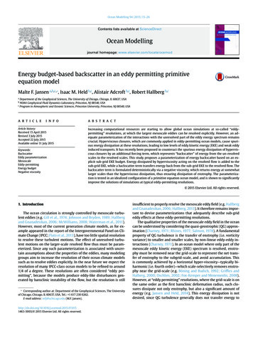
SGC SG-500 SmartPowerCube User’s Manual, Page 6‘barefoot’ transceiver operation.6.0 Front Panel DescriptionThis section describes the front panel controls and ports of the SG-500. These are described from left toright.Refer to the drawing above when reviewing the following descriptions.6.1 RF OUT & RF IN JacksConnect your station antenna, coupling or tuning device, or manual matching network to the RFOUT jack, and the coax jumper from the exciter (transceiver) to the RF IN jack.Warning: Do not operate the SG-500 without an antenna or suitable dummy load connected. Ifyou are uncertain of the antenna being used, test it at low power before applying 500 Watts to it.The SG-500 test VSWR before bringing the amplifier online. A high VSWR may preventamplifier operation.6.2 POWER ON/OFF SwitchThis powers the SG-500 on/off. When the power switch is in the off position, the amplifier isbypassed, allowing ‘barefoot’ operation.6.3 POWER LEDThis LED indicates when 14 VDC power is supplied to the SG-500.6.4 Power ConnectorSGC, 13737 SE 26th Street Bellevue, WA 98005 USA Ph: 425-746-6310, Fx: 425-746-6384, Email: sgc@sgcworld.comwww.sgcworld.comSGC RESERVES THE RIGHT TO CHANGE SPECIFICATIONS WITHOUT NOTICE Copyright SGC 2007
SGC SG-500 SmartPowerCube User’s Manual, Page 7This barrier strip with screw terminals allows DC power and RF ground connections.The top screw terminal is for 14 VDCThe middle screw terminal is for RF ground.The bottom screw terminal is for DC ground (return).Wiring TipsThe 14 VDC wiring should be #6 AWG diameter or larger, and kept as short as possible toavoid excessive voltage drop.The RF ground should be connected to suitable ground system. See other SGC publications forspecific antenna ground and counterpoise suggestions.The DC ground / return should also be #6 AWG wire diameter or larger.6.5 Status LED DescriptionThe status LEDs indicate the various amplifier parameters and any fault conditions that mayexist. There are two vertical columns of six LEDs. The left column indicates faults and transmitstatus. The right column indicates the active selected filter band. The function of the variousLED indicators are as follows:XMT – When this indicator is on, the amplifier is keyed for transmission. Normally the LED ison only when push-to-talk (PTT) is engaged.CURR – Warns that over-current condition (exceeding 100 A) exists, or if the current imbalancebetween amplifier modules exceeds 20%. When illuminated, the amplifier has tripped off-line.To reset the amplifier, power down and restart the unit.VOLT – Warns that an under-voltage condition (less than 10 VDC) exists. When illuminated, theamplifier has tripped off-line. To reset the amplifier, power down and restart the unit.IMPORTANT: A common cause of an under-voltage condition is that the power supply does nothave sufficient capacity for the power level or duty cycle. A larger power supply or battery-floatshould be employed. Voltage ‘droop’ under high current demands will not damage the SG-500,but may result in reduced output power.VOLT CURR – Invalid frequency used.VSWR - Warns that the samples VSWR has exceeded 4:1, and the power reflected back to theSG-500 is higher than acceptable. When illuminated, the amplifier has tripped off-line. To resetthe amplifier, power down and restart the unit.VSWR CURR – Input RF drive level out of range.TEMP – Warns that an over-temperature condition (greater than 55 degrees C) exists. This LEDstarts flashing at 55 degrees C, and increases in rate until it is on continuously – at which time theamplifier trips off-line. When this occurs, the amplifier has not been damaged and may beoperated again as soon as the indicator resumes flashing. Occasional flashing of this indicatorSGC, 13737 SE 26th Street Bellevue, WA 98005 USA Ph: 425-746-6310, Fx: 425-746-6384, Email: sgc@sgcworld.comwww.sgcworld.comSGC RESERVES THE RIGHT TO CHANGE SPECIFICATIONS WITHOUT NOTICE Copyright SGC 2007
SGC SG-500 SmartPowerCube User’s Manual, Page 8may occur during normal operation as the temperature of the amplifier rises.KEEP IT COOL: To avoid a high temperature condition, ensure adequate airflow aroundthe unit. Keep the cooling fins unobstructed, and do not stack other station components onthe SG-500. If the optional fan is installed, ensure it is plugged in and operating. Alsocheck the VSWR of the antenna system since a high VSWR increases the heat dissipationby the amplifier, causing faster temperature rise.ATTN – This LED indicates the input attenuator circuit is engaged. As input RF power levelincreases beyond 60-70 Watts, the attenuation increases automatically. The attenuator remainsengaged until the input drops to 30 Watts. If this happens, reduce exciter output power slightly.The LED may flash during voice peaks in SSB mode. LOW DRIVE FOR MAX POWER: Anilluminated ATTEN LED does not necessarily indicate the amplifier has tripped, or that a faultycondition exists. The SG-500 is designed to be driven to maximum output across either a low(10-60 W) or high (60-150W) input range. This is convenient for transceivers withoutcontinuously adjustable output power control. Maximum efficiency occurs when the SG-500 isdriven across the “low” input range, just below the point where the attenuator circuit is activated.ALC – ALC control provides adjustable ALC feedback voltage available via pin #3 (ALC) of theACCESS connector. This provides a positive ALC voltage range of approximately 1-5 VDC andshould not be used with transceivers utilizing negative ALC control.BAND FILTER SELECT – These LEDs indicate which of the input band-pass filters are active,as selected via manual or automatic control.BAND 1BAND 2BAND 3BAND 4BAND 5BAND 6LED is on when the 1.6 – 2.2 MHz filter is selectedLED is on when the 2.2 – 4.2 MHz filter is selectedLED is on when the 4.2 – 7.7 MHz filter is selectedLED is on when the 7.7 – 13.2 MHz filter is selectedLED is on when the 13.2 – 23.3 MHz filter is selectedLED is on when the 23.3 – 30 MHz filter is selected*Note – BAND 6 selection is disabled on US/Domestic version amplifiers. Licensed amateur andcommercial station operators may restore full coverage by following the procedure outlined in section 7.5of this manual.6.6 ACCESS ConnectorInserted into the ACCESS connector is the supplied 10 pin vertical plug which permits interfacing tocertain amplifier functions. Below this is a three pin horizontal connector controls the optional coolingfan unit (SGC part number #51-82)Access connector pins (from top to bottom) are described below:14 VDC – switched 14 VDC via the ON/OFF switch is present on this line (maximum 5A). Not to beused for powering station components drawing greater than 5A.GND – Chassis ground for control purposes available on this line.SGC, 13737 SE 26th Street Bellevue, WA 98005 USA Ph: 425-746-6310, Fx: 425-746-6384, Email: sgc@sgcworld.comwww.sgcworld.comSGC RESERVES THE RIGHT TO CHANGE SPECIFICATIONS WITHOUT NOTICE Copyright SGC 2007
SGC SG-500 SmartPowerCube User’s Manual, Page 9PTT – Push-to-talk control. This keys the amplifier circuitry when this line is grounded, and the PTTcontrol switch is set to manual.ALC – Automatic Level Control. A positive-going voltage is present on this line for use withtransceivers equipped for ALC input control. See the ALC control description.BAND 1 – BAND 6 – Bringing the appropriate line low (to ground) selects the desired input filter fordomestic operation when the front-panel FILTER SELECT switch is set to MANUAL. A simple rotaryswitch box can be constructed for this purpose. With the FILTER SELECT switch set to AUTO (forExport use), input filters are selected automatically each time you key the exciter.FAN – The optional cooling fan (SGC PN #51-82) cable plug inserts into this connector for power andfan control.7.0 Amplifier OperationThis section intends to get you on the air using your new amplifier with maximum ease. Before starting,check the following items. Ensure you are using a DC power source capable of providing at least 14 VDC at 40A or greater. Donot run the amplifier and transceiver from the same supply. Check that the power cables are firmly terminated at the power strip on both the amplifier and powersupply. The screws should be firmly tightened so that the cable lug terminals are flat against the strip forbest mechanical and electrical contact. Ensure the amplifier, transceiver (and any other station components such as the SG-235, or manualantenna coupler) are connected to a proper RF grounds.7.1 Test TransmissionStart by testing into a 50-ohm RF dummy load connected into the RF OUT jack on the SG-500. Werecommend installing a RF power meter in-line to monitor your transmitted output power.NOTE: You cannot perform this test with a 40A power supply.a. Set the PTT and FILTER select switches on the front panel to AUTO, and turn the power on. Thered LED should light.b. Select CW mode on your transceiver, and reduce the power output control to minimum. Note:other carrier modes (AM or FM) can be used if your transceiver does not have CW capability.c. Set the transceiver drive for 25W in CW mode. Turn the amplifier on and switch the radio tovoice, do a test count, and check that the power peaks on the meter. Turn the amplifier off, resetthe transceiver to 35W in CW and repeat voice test. When the voice peaks begin to activate theattenuator, you have passed the best level. Reduce the drive in 5W increments until the attenuatordoes not activate on voice peaks.d. Re-adjust the power output control just below the “break-point” (the top of the input range beforethe ATTEN circuit activates). You have now found the “sweet spot” at which you can drive theamplifier to maximum output with minimum drive. This is the recommended drive method to beused whenever practical.SGC, 13737 SE 26th Street Bellevue, WA 98005 USA Ph: 425-746-6310, Fx: 425-746-6384, Email: sgc@sgcworld.comwww.sgcworld.comSGC RESERVES THE RIGHT TO CHANGE SPECIFICATIONS WITHOUT NOTICE Copyright SGC 2007
SGC SG-500 SmartPowerCube User’s Manual, Page 10e. Now switch the transceiver to SSB, and transmit in a normal voice. The ATTEN circuit shouldnot activate, except on occasional voice peaks. (This concludes the test transmission. You cannow connect your station antenna and any other interconnections.)INPUT DRIVE LEVELS: The amplifier reduces power when the ATTEN circuit activates, and thenmust be driven through a higher input range to derive maximum output. Some 100-watt class amateurtransceivers may not be capable of producing sufficient output levels to drive the SG-500 for maximumoutput. Therefore, as stated before, we recommend using the low input range (10-50 Watts) for normaloperation.7.2 PTT KEYING: AUTO vs. MANUALThe amplifier can be keyed either manually or automatically – the best method will depend on yourpreference or application. Please note that whenever either PTT or Filter switches are changed, you mustturn the power off and back on to acknowledge the change.Manual Keying – This requires a wire connection to your transceiver; the PTT line (on the ACCESSconnector) needs to be pulled low (to ground) when your transceiver is keyed to transmit. This is thepreferred configuration to be used. Check with the documentation provided with your particulartransceiver for details on where to access this connection.Note: In manual PTT and Auto Filter mode, there will be a 10-15 msec delay while the CPUmeasures the frequency and selects the correct filter band.Automatic Keying – This uses RF sensing to detect when you transmit, and then brings the amplifier online. Although automatic keying requires no control line, a small associated delay may be encountered inSSB mode due to the “rise time” characteristic of SSB modulation.7.3 Mobile Installation of the SG-500If you are operating the amplifier mobile, please remember that the minimum size wire to be used fromthe battery to the amplifier is AWG #6. Heavier wire is preferred. The recommended way to install theamplifier in mobile installations is to install a second battery next to the amplifier.Operating HF mobile at the 500 watt level requires careful planning and understanding of RF andautomotive systems. The information needed regarding this is too expansive to be adequately dealt withhere in this manual.In response to customer inquiries, and from invaluable knowledge gained in this area by SGC researchstaff, SGC offers a highly informative publication called “Go Mobile at 500 Watts” which outlines thecomplete installation process in a variety of vehicles. This book is available for free download from ourwebsite at www.sgcworld.com.7.4 SG-500 and SG-235 InterconnectionsWhen the SG-500 is used with the SG-235 Smartuner , they form the heart of an outstanding 500 wattautomatically tuned HF system. Interconnections between the SG-500 and SG-235 permit amplifierkeying only when a proper antenna impedance match has been found. Only a few connections need to beSGC, 13737 SE 26th Street Bellevue, WA 98005 USA Ph: 425-746-6310, Fx: 425-746-6384, Email: sgc@sgcworld.comwww.sgcworld.comSGC RESERVES THE RIGHT TO CHANGE SPECIFICATIONS WITHOUT NOTICE Copyright SGC 2007
SGC SG-500 SmartPowerCube User’s Manual, Page 11made between these components, as outlined below:SG-235Coaxial cable plugYellow wireBlue wireWhite wireSG-500RF out jackPTT line (pin #4)Smartlock ProBlue wireWhite wirePlease refer to the SG-235 manual for further coupler wiring details.Remote ON/OFF Power Control: The SG-500 can be turned on/off remotely via a connector provided forthis purpose. To the left of the front panel PTT selection switch is a vertical 4-pin header. A jumpercomes installed across the top two pins, which are in series with the front-panel ON/OFF switch line. Thebottom two pins provide indicator output for a LED, and are in parallel with the front panel PWR LED.SGC provides a Remote Control box for the amplifier that can be purchased separately (Cat. #52-88).To install a custom remote on/off switch, remove the upper jumper and connect your switch leads in itsplace using a push-on connector. Likewise, a remote LED can be connected to the lower two pins ifdesired (LED ground connection on the lower pin). Leave the front panel on/off switch in the ONposition to enable your remote line in this configuration.7.5 DOMESTIC vs. EXPORT Amplifier VersionsAmplifiers manufactured for US domestic sales are disabled to operate above 24.5 MHz, Export versionsof the SG-500 do not have this restriction.Amateur radio, MARS, or CAP operators holding valid, current FCC station licenses mayoperate the SG-500 on US amateur bands above 24.5 MHz or other frequencies, limited to theoperating privileges aut
5.0 Power Supplies Page 5 5.1 Battery Power Supplies Page 5 5.2 Alternative Power Sources Page 5 6.0 Front Panel Description Page 6 6.1 RF Out and RF In Jacks Page 6 6.2 Power On/Off Switch Page 6 6.3 Power LED Page 6 6.4 Power Connector Page 6 6.5 Status LED Descriptions Page 7 6.6 Access Connector Page 8 7.0 Amplifier Operation Page 9