Transcription
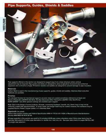
PIPE HANGERSAND SUPPORTSTHE GROUPWith 24 companies in 19 countriesWitzenmann is number 1 in the industry worldwide.Witzenmann GmbHWitzenmann Sachsen GmbHHeadquartersÖstliche Karl-Friedrich-Str. 13475175 PforzheimTelefon 49 7231 581-0Fax 49 7231 izer Straße 3808412 WerdauTelefon 49 3761 45-0Fax 49 3761 chsen.de1756uk/1/10/15/15World leaderWitzenmann is a global group specialising in the design and manufacture of flexiblemetal elements. Guided by our vision of „managing flexibility“, our company hasbecome renowned as a reliable manufacturer and as the innovative developmentpartner of choice within the industry. Today, Witzenmann offers the widest productrange worldwide for the most diverse areas of application. This enables us to offerthe correct solutions time and time again.
The details are provided to the best of our knowledge,but the contents are not legally binding.We reserve the right to make changesin the interests of technical progress.Updated 10/2015
CONTENTSGeneral information4Quality by Witzenmann4The hanger system6Planning and design8HYDRA Spring hangers/supports14VH sizes, load groups, load levels18Spring hangers20Spring supports23Double hanger with traverse26HYDRA Constant hangers/supports28Load groups, load levels32Constant hangers/supports34HYDRA Connecting elements44HYDRA Pipe clamps59Horizontal clamps62Riser clamps78Dynamic components86Installation instructions1081756uk/1/10/15/153
QUALITY BYWITZENMANNConverting our prominent development expertiseperfectly into customised product solutions that fulfilthe highest requirements - this is our standard.Durability and absolute operational reliability are essentialfor a company aiming to be the quality leader.It is not only DIN ISO 9001 / TS 16949 certification, but also awide variety of national and international approvals and certifications such as VDA 6.1, J ATEX (94/9 CE) or DESP (97/23 CE)that constitute "Hydra - Quality by Witzenmann". Our customers include major companies involved in petrochemicals,industry and plant engineering and construction, power plantoperators and suppliers in the energy sector.Calibration testsThe suitability of the hanger and its accessories for use inpower plants has been verified by suitability tests, such asthose of the VGB (Association of Major Power Plant Operators) and specified in accordance with DIN 13480. As well asthe checking of the QA system, this includes the constructionand calculation documents, the verification of suitable materials as well as comprehensive functional, load and lifespantests. The successful verification took place under the supervision of the VGB through the TÜV Süddeutschland.StandardsThe basic standards on which the design is based are the VGBguidelines R 510 L (1996), "Pipe supports", and KTA 3205.3(1989), "Mass-produced standard supports". In addition, thefollowing German and foreign regulations are also taken intoaccount:p DIN EN 13480 "Industrial pipelines"p AD datasheets for pressure vessels (D)p DIN 18800, Steel structures (D)p TRD, Technical rules for boilers (D)p ANSI B 31.1/3 (USA)p ASME, Boiler and Pressure vessel Code, Sec. III,Subsection NF (USA)p MSS SP 58p BS, British Standard (GB).Conformity in detail will be examined when needed.1756uk/1/10/15/155
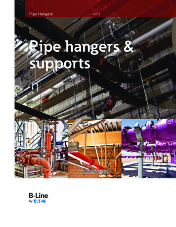
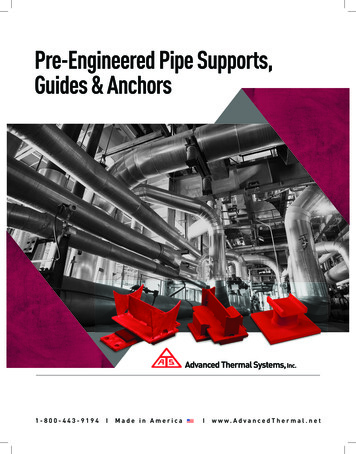
THE HANGERSYSTEMLoad chain with spring hangersand horizontal pipe clampsOur standard range of hangers, supports and accessories isdesigned, like our entire pipe support range, as a comprehensive, practically oriented, consistent system.To make planning and selection simple and reliable, we offera standard range with variants that enable rapid and inexpensive adjustment to the particular case of need.Load chainsFollowing selection of hangers and clamps, complete loadgroups can be designed.Load group withconstant hanger attachedand horizontal pipe clampStarting initially from the hanger type, the upper connectionto the load-bearing structure is defined. This is followed bythe appropriate connection to the pipe clamp, including thethreaded part. The distance between these two is bridged withthreaded rods, which may be interrupted with rod couplings.Threaded rods should be ordered with excess lengths so theycan be adapted to the real circumstances on the constructionsite by cutting.The selection of the required connecting parts has been significantly simplified by our hanger system, which classifies allconnecting parts as well as hangers and clamps load groups(LGV).Double load chain withspring hangers, traverse andhorizontal pipe clampsThe fitted measurement "E" indicated for all products simplifies adding up the entire length of the load group.CONTINUOUS LOAD GROUPSMAKE FOR RELIABLE PLANNINGThe load groups of the connecting parts assign together partsof the same nominal load FN taking into account the samethread diameter. For all spring hangers and constant hangers,the associated load group LGV is indicated and is part of thetype designation.Load group LGVNominal load FN in kNConnectionsThread diameter 300400500M 12M 16M 20M 24M 30M 36M 42M 48M 56M 64M 72M 80M 90Inch1/25/83/411⅛11/213/4221/421/223/4331/2Bolt -1511-1611-1713-1814-1916-1917-2018-2019-20Spring hangers Nominal load FN in kNVH sizeConstanthanger12Max. permissible required loadFS1) in kNpossibleCH size 2)1)15% adjustment reserve taken into account2)see Table page 32DEFINITIONSModel seriesName for a product series in the hanger range, consisting ofthree letters; it is part of every type designation.Example: FHD stands for spring hanger with double lug.Load group (LGV)Categorizing term for connecting parts, based on theassociated thread diameter. The same load group meansthe same nominal load and the same design safety factor;it is part of the type designation for hangers, supports andconnecting parts.Example: Load group 36 includes all connecting parts with orthat fit thread diameter M36; its nominal load is FN 70 kN,(see table above).VH sizeCategorizing term for spring hangers and spring supports. Thesame load size is assigned as number amount to the springhangers with a specific nominal load FN regardless of the typeseries or nominal travel; it forms part of the spring hanger typedesignation.Example: FHD 07. stands for the seventh size of springhangers with double lug, its nominal load is FN 20 kN, (seespring hanger table from page 20).CH sizeCategorizing term for constant hangers and constant supports. The same CH size is assigned as a number amountto the constant hangers with a specific CH, the product ofnominal load and nominal travel (FN · sN); it forms part of theconstant hanger type designation.Example: KHD 08. stands for the eighth size of the constanthanger, horizontal, with double lug (see constant hangertables from page 34).61756uk/1/10/15/151756uk/1/10/15/157
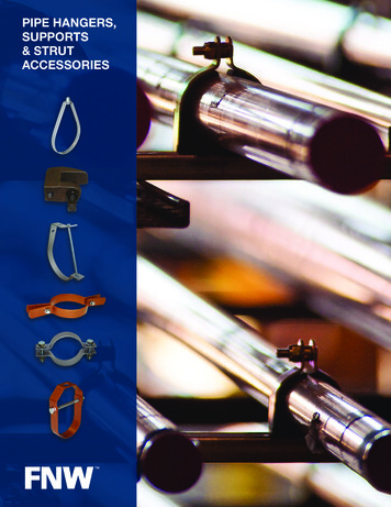
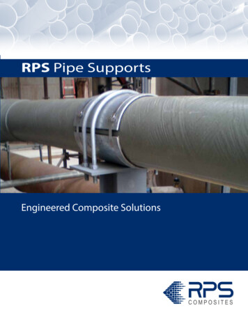
PLANNINGAND DESIGNittmFactual, 0rPeedcanlerto1)ee fiFactual, usR, topsS, upwardsHanger travel ssR, bottomConditions for the hanger and clamp layoutAlongside the special boundary conditions, such as applicable regulations, prescribed acceptances, required documentation, etc. special criteria are specified depending on thepipe supports position.Constant hangers and constant supportsLoad/Travel characteristic, tolerance limitsAdjustment rangeldTaking into account load tolerances andfriction componentsWhen calculating the pipeline systems the load tolerancesand especially the unavoidable friction components must betaken into account. No matter how small they may be; if theyare not taken into account as force components that eachapply against the movement, they can completely changethe operating behaviour of a highly flexible system comparedto the calculation. This may result in unintended positionchanges of the pipelines with the danger of condensationgathering, water hammers, unintended tension increasesand other disruptions.Factual, 0Factual, uPermitted tolerance field 1)Factual, averageLoad FThe tolerance limits prescribed in the recognised standards(e.g. VGB-R 510 L, KTA 3205.3) therefore permit maximumdeviations for spring and constant hangers of only 5% fromthe theoretical loads, as made clear in the following diagrams.In addition, load adjustment options and adequate travelreserves are required to be able to adapt the devices duringfitting of the actual loads and travels.Spring hangers and spring supportsLoad/Travel characteristic, tolerance limitsLoad F in %Real hanger behaviourTo be able to predict the later real behaviour of the pipesadequately with computer pipe analyses, the planner must beable to predict that the planned hanger will behave as plannedwithin the entire operating time.Spring travel xsR, top1) Permitted tolerances with angled load application: 6 %sS, upwardssR, bottomHanger travel sDefinitionStart load:Nominal load:Required load, cold (cold load):Required load, warm (warm load):Spring rate:Spring travel, total:Nominal travel:Required travel:Travel reserve:R FNxNFminFNFk, sFw, s xNsNsSsR1) Permitted tolerances with angled load application: 6 %FN - FminsNDefinitionNominal load:FN(Maximum load of the constant hanger)Required load:Fsset average load:Factual, averageCondition for theaverage setting:Nominal travel:Required travel:Travel reserve:81756uk/1/10/15/151756uk/1/10/15/15 Fs - Factual, average Fs 0.02sNsSsR9
DESIGN CRITERIAFLEXPERTE – DESIGN AND CALCULATIONBasic decision regarding hanger selectionBefore the detailed hanger selection, an initial decision mustbe made about whether a rigid or moveable hanger is required. Then it must be settled whether a spring hanger issufficient or a constant hanger is required. (In this respect,when hangers are discussed, supports are included in this.)p Level requirements for hanger/support arrangement (defines connection variants)p Distance available from centre of pipe to steel structure(defines design of the load chain)p Set-up type, e.g. inside building or in open air (definescorrosion protection measures)The rigid, hanging suspension element is then selected if novertical movement occurs or is authorised at the suspensionpoint; however, horizontal movement components are permitted to a limited extent.Pipe clampsHorizontal or riser clamps are specified by the orientation ofthe pipeline at the particular suspension point.Spring hangersThese components, which are cheaper than constant hangers, can then be used when the vertical movement to beabsorbed is not too large - max. 60 mm - and the suspendedpipe system with its component connections can easily bear adifferent in the loads between installation and operating state(load change); 25% of the heat load would typically be seen asa permitted load change in this respect.Constant hangersThese components, which are more complex than springhangers, are required when larger vertical movements mustbe absorbed - 60 mm and more - or when the load deviationsmay not exceed 5%, in order to avoid unpermitted loads oncomponent connections or critical pipe sections.Note:With spring hangers, a decision must be made in advanceabout whether weight forces must be compensated for in thewarm or cold state of the pipeline. In the first case, additionalpipe loads are avoided in the warm state, in the other caseinstallation is simpler, as "swimming in" of the pipe can beavoided, i.e. weight compensation is possible with disengagedconnections.Spring hangers and constant hangersp loads to be borne, taken from pipeline calculation(required load)p Self-weight of traverses, pipe shoes and hanger housingto be borne, if applicablep Vertical movements to be absorbed (required travel)p Direction of the vertical movement from cold to warm(up or down)p horizontal movement occurring at the same time(defines length or angular load of the suspension element)p Type of hanger connection to the steel structure(hanging, attached/welded, screwed, clamped)10Ever shorter development cycles call for sound design andrelevant calculation results even in the early stages of development. Up-to-date FEM programs can be used to determinemost of the important characteristics of parts by calculationas early as in the design phase. Not only the tensions, but alsofunctional characteristics such as static and dynamic rigidity,resonant frequencies and stability limits are used as the basisof service life calculations.We can furnish our customers at an early stage with CADmodels of Witzenmann products for static and dynamic FEManalyses. Thus, our customers can integrate componentsmade by Witzenmann into their calculations with all requisiteproperties and without additional effort.The selection of materials is dependent on the clamptemperature to be expected; in the process the temperaturedrop between the medium temperature and the higheststressed clamp area is to be taken into account, in order toavoid receiving unnecessarily overdimensioned clamps.(see from page 61)Through appropriate measurement of the connectablethree-bolt and grip clamp as well as the connecting lugsfor the two-bolt clamps, we have ensured that at the highestpermissible clamp temperature the temperature of theconnecting thread part (eye nut or clevis) will not be higherthan 80 C.Knowledge by WitzenmannIt is recommended that the pipe is positioned in shear pinsin rigid suspensions, in shear lugs in spring suspensions; thisapplies independently of any pipe tilt that occurs.p Operating load at support pointp Diameter of the pipep Temperature of the medium (operation, design, etc.)p Anticipated insulating thickness of the pipelinep Orientation of the pipeline (horizontal, vertical)p Spans with riser clampsp Material requirements for the pipe clamps (e.g. austenite)p Normally, additional loads are not taken into account in theselection of hangers and clamps, such
Standards The basic standards on which the design is based are the VGB guidelines R 510 L (1996), "Pipe supports", and KTA 3205.3 (1989), "Mass-produced standard supports". In addition, the following German and foreign regulations are also taken into account: p DIN EN 13480 "Industrial pipelines" p AD datasheets for pressure vessels (D)