Transcription
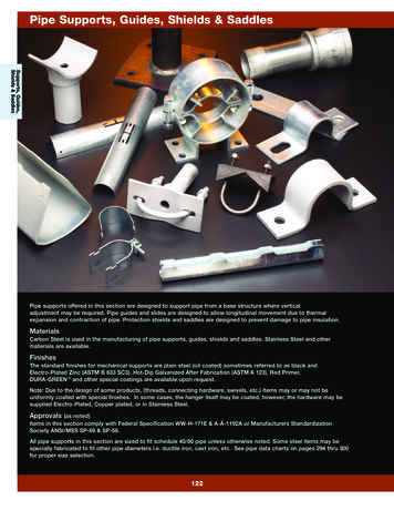
RPS Pipe SupportsEngineered Composite Solutions
Pipe SupportsTable of ContentsGeneral Notes.Page 5Pictorial IndexPipe Supports.Page 7Duct Supports.Page 12Pipe SupportsFigure S1: U-Strap W/ Shield (1” – 12” Diameter).Page 14Figure S2: U-Bolt W/ Shield (1” – 12” Diameter).Page 15Figure S4: Clevis Hanger (1” – 18” Diameter).Page 16Figure S5: Wide Clamp Hanger (1” – 18” Diameter).Page 17Figure S5: Wide Clamp Hanger (20” – 60” Diameter).Page 18Figure S7: FRP Wear Pad (1” – 12” Diameter).Page 19Figure S8: Slide Shield (1” – 12” Diameter).Page 20Figure S9: Pipe Cradle (1” – 10” Diameter).Page 21Figure S9B: Pipe Cradle (12” – 60” Diameter).Page 22Figure S10: Pipe Stand - Fixed Height (1” – 8” Diameter).Page 23Figure S11: Pipe Stand - Adjustable Height (1” – 8” Diameter).Page 24Figure S12: Flange Slide (1” – 10” Diameter).Page 25Figure S12B: Flange Slide (12” – 30” Diameter).Page 26Figure S12B: Flange Slide (36” – 60” Diameter).Page 27Figure S13: Flange Guide (1” – 10” Diameter).Page 28Figure S13B: Flange Guide (12” – 30” Diameter).Page 29Figure S13B: Flange Guide (36” – 60” Diameter).Page 30Figure S14: Flange Anchor (1” – 30” Diameter).Page 31Figure S14: Flange Anchor (36” – 60” Diameter).Page 32Figure S15: Flange Linestop (1” – 10” Diameter).Page 33Figure S15B: Flange Linestop (12” – 30” Diameter).Page 34Figure S15B: Flange Linestop (36” – 60” Diameter).Page 35Figure S16: Flange Hanger (1” – 18” Diameter).Page 36Figure S17: Flange Riser Guide (12” – 30” Diameter).Page 37Figure S17: Flange Riser Guide (36” – 60” Diameter).Page 38Figure S18: Flange Riser Support (12” – 60” Diameter).Page 392
Pipe SupportsFigure S19: Flange Riser Support W/ Guides (12” – 60” Diameter).Page 40Figure P7: Elbow Support Slide Plate (2” – 10” Diameter).Page 41Figure P7B: Elbow Support Slide Plate (12” – 24” Diameter).Page 42Figure P8: Base Slide (1” – 10” Diameter).Page 43Figure P8L: Base Slide – Low Profile (1” – 10” Diameter).Page 44Figure P9: Base Guide (1” – 10” Diameter).Page 45Figure P9L: Base Guide – Low Profile (1” – 10” Diameter).Page 46Figure P10: Base Anchor (1” – 10” Diameter).Page 47Figure P10L: Base Anchor – Low Profile (1” – 10” Diameter).Page 48Figure P13: Riser Guide (1” – 20” Diameter).Page 49Figure P13: Riser Guide (24” - 60” Diameter).Page 50Figure P14: Riser Support (1” - 10” Diameter).Page 51Figure P14: Riser Support (12” - 30” Diameter).Page 52Figure P14: Riser Support (36” - 60” Diameter).Page 53Figure P15: Double Rod Riser Hanger (1” - 10” Diameter).Page 54Figure P15: Double Rod Riser Hanger (12” – 30” Diameter).Page 55Figure P16: Riser Support W/ Guides (1” – 10” Diameter).Page 56Figure P16: Riser Support W/ Guides (12” – 30” Diameter).Page 57Figure P16: Riser Support W/ Guides (36” – 60” Diameter).Page 58Figure P17: Base Linestop (12” – 30” Diameter).Page 59Figure P17: Base Linestop (36” – 60” Diameter).Page 60Figure P18: Base Slide (12” – 30” Diameter).Page 61Figure P18: Base Slide (36” – 60” Diameter).Page 62Figure P19: Base Guide (12” – 30” Diameter).Page 63Figure P19: Base Guide (36” – 60” Diameter).Page 64Figure P20: Base Anchor (12” – 30” Diameter).Page 65Figure P20: Base Anchor (36” – 60” Diameter).Page 66Figure XL12: Extra Large Slide (66” – 108” Diameter).Page 67Figure XL13: Extra Large Guide (66” – 108” Diameter).Page 68Figure XL14: Extra Large Anchor (66” – 108” Diameter).Page 693
Pipe SupportsDuct SupportsFigure D1: Duct Clamp Hanger (20” – 60” Diameter).Page 70Figure D3: Duct Cradle Base Slide (20” – 60” Diameter).Page 71Figure D4: Duct Base Linestop (20” – 36” Diameter).Page 72Figure D4: Duct Base Linestop (42” – 60” Diameter).Page 73Figure D5: Duct Base Slide (20” – 36” Diameter). Page 74Figure D5: Duct Base Slide (42” – 60” Diameter).Page 75Figure D6: Duct Base Guide (20” – 36” Diameter).Page 76Figure D6: Duct Base Guide (42” – 60” Diameter).Page 77Figure D7: Duct Base Anchor (20” – 36” Diameter).Page 78Figure D7: Duct Base Anchor (42” – 60” Diameter).Page 79Figure D16: Duct Riser Guide (20” – 30” Diameter).Page 80Figure D16: Duct Riser Guide (36” – 60” Diameter).Page 81Figure D17: Duct Riser Support W/ Guides (20” – 30” Diameter).Page 82Figure D17: Duct Riser Support W/ Guides (36” – 60” Diameter).Page 83Support OptionsFigure O1: Variable Spring Hanger Supports.Page 84Figure O2: Slide Bearings.Page 85Figure O3: Base Plates.Page 86Figure O4: Guide Clips.Page 87Figure O5: Expansion Joint W/ Control Rods.Page 88Painting Specification.Page 894
Pipe SupportsPipe Support General Notes1)2)3)10) Support dimensions are based on typical wall thicknesses and may varydepending on the actual O.D. and load requirements (See Note 3).The following catalog support configurations are designed for thelisted allowable loads. If actual load requirements differ from thedefined allowable loads, configurations and materials can be alteredto accommodate the load requirements. The defined vertical loadsare downward in direction unless otherwise noted. Please specify allload requirements with placement of order.11) Flange support dimensions for sizes up to 24” diameter pipe arebased on ANSI B16.5 CL150 flange drilling and may vary dependingon the actual drilling class and load requirements.12) Flange support dimensions for sizes above 24” diameter pipe arebased on ASME B16.47 Series A CL150 flange drilling and may varydepending on the actual drilling class and load requirements.The defined support loads and designs are based on typical FRPand plastic pipe/duct system arrangements, design parameters andspans between supports. Support designs and configurations can bealtered to accommodate specific project needs.13) FRP flanges require a full back facing for use with flange plate supports.Allowable loads for pipe supports are based on 150 PSI rated FRPpipe wall thicknesses. Allowable loads and designs for duct supportsare based on 25 PSI rated FRP wall thicknesses. If the actual pressureratings differ, the support designs can be altered to safely distributeth
10) Support dimensions are based on typical wall thicknesses and may vary depending on the actual O.D. and load requirements (See Note 3). 11)Flange support dimensions for sizes up to 24” diameter pipe are based on ANSI B16.5 CL150 flange drilling and may vary depending on the actual drilling class and load requirements.