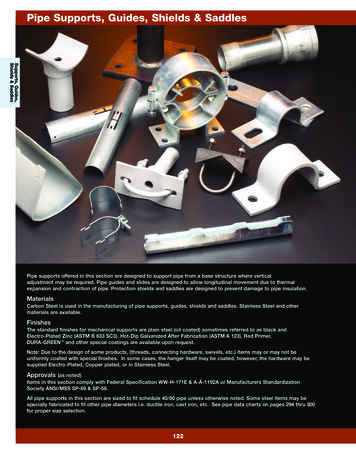
Transcription
Pre-Engineered Pipe Supports,Guides & AnchorsAdvanced Thermal Systems, Inc.1-800-443-9194IM a d e i n A m e r i c a 12Iwww.AdvancedThermal.net
Advanced Thermal Systems, Inc.www.AdvancedThermal.netGeneral Guidelines for Guiding & Supporting Pipe1. The Primary and Intermediate Guide Spacings shown are forstandard weight pipe and are satisfactory for above ground ortunnel installation. They are applicable to the following:A. Single Expansion Joints with an integral anchor or SingleExpansion Joints installed immediately adjacent to a lineanchor.B. Double Expansion Joints.2. When a single expansion joint without base is installed in thecenter (or approximate center) of a pipe run, the primary guidespacing should be modified as follows:A. Sizes 1-1/2” to 4” inclusive: Six (6) pipe diameters from eachend of the expansion joint.B. Sizes 5” to 24” inclusive: Three (3) pipe diameters from eachend of the expansion joint. To preclude the possibility of cockingthe slip of, heavier expansion joints, (sizes 6” and larger), asliding support under the expansion joint body is recommended.3. For buried conduit systems with expansion joints installed inmanholes or vaults, a guide should be installed at the terminationof the conduit pipe at the manhole wall (e.g.,gland or link seal). Inaddition, consideration should be given to providing a “Moment”guide within 10 feet of the manhole wall (not to be integrallyattached to the manhole wall). LOW FRICTION NON-METALLIC“BRONZALON ” GUIDE INSERTS SHOULD BE SPECIFIED FOR THEEXPANSION JOINT.4. GUIDE/SUPPORT SELECTION:PRIMARY GUIDES: The preferred designs are those that guide thepipe radially such as the ATS Models “GA”. For low profile systemsthe ATS Low Friction Figure 100, 101, and 101 M Series GraphiteGuides can be used, (consult factory for applications).INTERMEDIATE GUIDES: The ATS Low Friction Figure 100,101and 101 M Graphite Guides are recommended to reduce frictionforces and eliminate corrosion of the sliding components.INTERMEDIATE SUPPORTS: The ATS Low Friction Figure 200,201 and 201 M Graphite Supports are recommended to reducefriction forces and eliminate corrosion of the sliding components.5. The pipe guiding and support spacing shown in Table 1 is thesuggested maximum span as specified by the ASME/ANSI PowerPiping Code B31.1, and is applicable for horizontal straight runsof pipe without concentrated loads such as valves or heavy fittingsbetween supports. The span distance applies to standard weight orheavier pipe operating at a maximum temperature of750 F (400 C).6. LATERAL FORCES ON GUIDES:Pipe Alignment Guides and their support structure may besubjected to lateral forces in addition to the frictional forces alongthe longitudinal axis of the pipe. It is recommended that alignmentguides be designed to resist a lateral force equal to 250 lb./inch ofnominal pipe size.27. THERMALLY INDUCED CHANGES OF PIPELINES:Pipelines will always change in length as the temperature of thepipeline changes. This change must be accommodated by somemethod, either by natural flexibility of the pipeline or by use of anexpansion device. Advanced Thermal Systems “TP2” Thermal PakExpansion Joints are the ideal selection when long straight runs ofpipe are involved.Table 2 is used to determine the total change in length of the pipe runbased upon the maximum and minimum temperatures of the system.The net change in length of the pipe run per 100 ft. of piping is thealgebraic difference between the expansion constant at the highesttemperature and the expansion constant at the lowest temperature.This difference is then multiplied by the total length of the pipe rundivided by 100.EXAMPLE:Determine the total change in length of a 250 feet long pipe run that isdesigned for 300 psig saturated steam (422 F) and is being installedoutside where the ambient temperature may reach 20 F.(3.44 – 0.15) x (250 100) 8.23 in.NOTE:The minimum temperature may not be the installation temperature.Table 1: Pipe Alignment Guide and Support SpacingNOMINALPIPE SIZE(NPS)PRIMARY (1st)GUIDE FROMEND(S) OFSLIP (feet)1 1 222 1 234568101214161820241 1 222346688121216202025INTERMEDIATE GUIDESPACING (feet)PRESSURE 5859511078111216222735505560708090100PIPE SUPPORTSPACING (Feet)WATER 2730323537394212 Proudly Manufactured in the U.S.A.
Advanced Thermal Systems, Inc.1-800-443-9194Low Friction Graphite Pipe Guides and Pipe SupportsTable 2: Thermal Expansion of Steel Pipe (inches per 100 ft.)SATURATED STEAM VACUUM INHG BELOW 212 F, PRESSURE,PSIG ABOVE 212 1234627053080TEMP. FCARBON & CARBONMOLYBDENUM 6.577.007.237.457.668.108.34Pre-Engineered Pipe Supports, Guides & Anchors 12ATS QUALITY AND SERVICE FOR PROVEN RELIABILITY: Standard Designs for Welding or Bolting to support structure. 1/2” Thick Graphite on both upper and lower assemblies.Epoxy bonded for applications up to 350 F, epoxy bonded andmechanically attached for applications over 350 F.** Furnished standard with shop primer on all carbon steelcomponents. Hot-Dip Galvanized or Epoxy Paint also available. Custom designs available with additional axial and/or lateralmovement or to accommodate thicker insulation.GRAPHITE PROPERTIESCompressive Strength 2000 psiTemperature Range-20 F to 750 FCoefficient of Friction0.15Table 3: ATS Low Friction Guide and Support Selection TablePIPE SIZE(NPS)STYLEATS FIG NO.1 to 2 1 23 to 241 to 2 1 23 to 243 to 243 to 24Not InsulatedNot InsulatedNot InsulatedNot M201MAXIAL8”8”8”8” 4” 4”MOVEMENTLATERAL00 3” 3”0 3”Table 4: Available FinishesFINISHCODEFINISHTYPEPEGOne Coat Shop PrimerEpoxyHot-Dip GalvanizedORDER BY CATALOG NUMBER24” Fig. 201 W 4 8 3 A PFinish (Table 4)Graphite Mechanical Attachment:A - 350 F (omit for 350 F)Lateral Movement, in.(omit for Fig. 100, 101 and 101-M)Axial Movement, in.Insulation Thickness, in.Attachment: W - Weld, B - BoltFigure No. (Table 3)Pipe Size, NPS** Specify Maximum Service Temperature3
Advanced Thermal Systems, Inc.www.AdvancedThermal.netLow Friction Guides and Supports for Use in Hot ServiceFIG. 100-W2" MAXIMUMINSULATIONTHICKNESSPIPE MOVEMENTPIPE MOVEMENT2" MAXIMUM CINSULATIONTHICKNESSCPIPE SIZEC 1/81 "A16A1/2" 1/8CCLOWERBASEASSEMBLY1"168"C8"COLD TO HOT11"11"141414141-5211 -5211-5211 -5218"8"AXIAL MOVEMENTAXIAL D TO HOTPIPE SIZE1/2" GRAPHITE 1/2" GRAPHITEPLATES EPOXY PLATES EPOXYBONDED TO STEELBONDED TO STEELCOMPONENTS EL4"4"141414141-5211 -5211-5211 -521FIG. 200-W2" MAXIMUM2" MAXIMUMINSULATIONINSULATIONTHICKNESSTHICKNESSPIPE MOVEMENTPIPE MOVEMENTCC11"C 1/8 1/8AA1/2"1/2"1414COLD TO COLDHOT TO HOTPIPE SIZEPIPE SIZECCC11"1-5211 -5218"8"AXIAL MOVEMENTAXIAL MOVEMENTLOWER LOWERBASEBASEASSEMBLYASSEMBLY 3" LATERAL 3" LATERALMOVEMENTMOVEMENT1"1"11114411-524111 -5241UPPER UPPERT-BAR T-BARSUPPORTSUPPORTASSEMBLYASSEMBLYSTEEL STEEL1/2" GRAPHITE1/2" GRAPHITEPLATES EPOXYPLATES EPOXYBONDED BONDEDTO STEELTO STEELCOMPONENTSCOMPONENTS4"4"141411-524111 -52411-5211 -521Fig. 201-B Low Friction Support412 Proudly Manufactured in the U.S.A.
Advanced Thermal Systems, Inc.1-800-443-9194Low Friction Guides and Supports for Use in Hot ServiceFIG.100 and FIG. 200DimensionsFIG. 100-B2" MAXIMUMINSULATIONTHICKNESSPIPE MOVEMENTCCOLD TO HOTPIPE SIZE11"8"AXIAL MOVEMENT 1/8ALOWERBASEASSEMBLY1"161"210"5" DIA82 HOLES811/2" GRAPHITEPLATES EPOXYBONDED TO STEELCOMPONENTSUPPERT-BARASSEMBLY1/2"1-5211 -521414CC2"PIPE MOVEMENTC1414COLD TO HOTPIPE SIZE11"CC 1/81/2"5" DIA82 HOLES 3" LATERAL MOVEMENT1"1143"124UPPERT-BARASSEMBLYFig. 101-W Low Friction Support / GuidePre-Engineered Pipe Supports, Guides & Anchors 121-5211 -5218"AXIAL MOVEMENTLOWERBASEASSEMBLYA11 1 41 1 222 1 2DIM.(in.)A5 5 165 1 25 5 85 13 166 1 16GRAPHITEBEARING WEIGHT(lbs.)AREA(Sq. in.)999992222222222NOTES:1. See Page 2 for generalinformation pertaining to Figure100 and Figure 200 Pipe Guidesand Supports.4"FIG. 200-B2" MAXIMUMINSULATIONTHICKNESSPIPESIZE(NPS)2. Dimension “A” is for maximuminsulation thickness shown. Forapplications requiring thickerinsulation, Dimension “A” willincrease accordingly.3. Graphite is epoxy bondedto steel for applications upto 350 F, epoxy bonded andmechanically attached forapplications over 350 F.1/2" GRAPHITEPLATES EPOXYBONDED TO STEELCOMPONENTS2"4"Fig. 101M-W Pre-Insulated Low Friction Support / Guide5
Advanced Thermal Systems, Inc.www.AdvancedThermal.netWeld Down Base Low Friction Graphite Guidesand Supports for Use in Hot ServiceFIG. 101-WPIPE MOVEMENTB MAXIMUMINSULATIONTHICKNESSCOLD TO HOTCCE"EPIPSIZC" 1/88"AXIAL MOVEMENTLOWER BASEASSEMBLY1"16A1414C1/2" GRAPHITE PLATESEPOXY BONDED TOSTEEL COMPONENTSUPPER CRADLEASSEMBLYEF11 -5211 -52SUPPORTSTEELD141411 -5211 -52FIG. 201-WPIPE MOVEMENTB MAXIMUMINSULATIONTHICKNESSCOLD TO HOTCCE"IPESIZ"PAC1414C8"AXIAL MOVEMENTLOWER BASEASSEMBLY 1/811 -5211 -521/2" GRAPHITE PLATESEPOXY BONDED TOSTEEL COMPONENTSUPPERCRADLEASSEMBLYE 3" LATERAL MOVEMENTSUPPORTSTEELD141411 -5211 -52FDIMENSION (inches)PIPESIZE(NPS)ABCDE34568101214161820247 1 87 5 88 3 169 13 1610 13 1611 7 812 7 813 1 214 1 215 1 216 1 218 1 23334444444441111111212121212121212124445555555551 21 21 21 21 21 21 21 21 21 21 21 2GRAPHITE BEARING AREA(Sq. in.)161616202024242424242428FIG NO.101-WF9 1 29 1 29 1 210 1 210 1 53539404040404556NOTES:1. See Page 2 for general information pertaining to Figure 101 and Figure 201 Pipe Guides and Supports.2. Dimension “A” is for nominal insulation thickness shown (Dimension “B”). For applications requiring thicker insulation, Dimension“A” will increase accordingly.3. Graphite is epoxy bonded to steel for applications up to 350 F, epoxy bonded and mechanically attached for applications over 350 F.612 Proudly Manufactured in the U.S.A.
Advanced Thermal Systems, Inc.1-800-443-9194Bolt Down Base Low Friction Graphite Guidesand Supports for Use in Hot ServiceFIG. 101-BPIPE MOVEMENTB MAXIMUMINSULATIONTHICKNESSCOLD TO HOTCCE"PE"PIA 1/8SIZC1414C8"AXIAL MOVEMENTLOWERBASEASSEMBLY1"161/2" GRAPHITE PLATESEPOXY BONDED TOSTEEL COMPONENTSUPPERCRADLEASSEMBLYEJFD4 HOLESG DIA.H11 -5211 -52FIG. 201-BPIPE MOVEMENTB MAXIMUMINSULATIONTHICKNESSCOLD TO HOTC1414CE"PE"PIASIZCC8"AXIAL MOVEMENTUPPER BASEASSEMBLY 1/811 -5211 -52G DIA4 HOLES1/2" GRAPHITE PLATESEPOXY BONDED TOSTEEL COMPONENTSUPPERCRADLEASSEMBLYE 3" LATERAL MOVEMENTFDJHFIG NO.PIPESIZE(NPS)DIMENSION (inches)ABCDEFG34568101214161820247 1 87 5 88 3 169 13 1610 13 1611 7 812 7 813 1 214 1 215 1 216 1 218 1 23334444444441111111212121212121212124445555555551 21 21 21 21 21 21 21 21 21 21 21 22 1 22 1 22 1 23 1 43 1 43 1 43 1 43 1 43 1 43 1 43 1 435 85 85 83 43 47 87 87 87 87 87 81GRAPHITE BEARINGAREA (Sq. 01-BHJHJlbs.lbs.11 1 211 1 211 1 213131515151515151610101011 1 411 1 413131313131313 3 414 1 214 1 214 1 216161818181818181913131314 1 414 1 416161616161616 3 OTES:1. See Page 2 for general information pertaining to Figure 101 and Figure 201 Pipe Guides and Supports.2. Dimension “A” is for nominal insulation thickness shown (Dimension “B”). For applications requiring thicker insulation, Dimension“A” will increase accordingly.3. Graphite is epoxy bonded to steel for applications up to 350 F, epoxy bonded and mechanically attached for applications over 350 F.Pre-Engineered Pipe Supports, Guides & Anchors 127
Advanced Thermal Systems, Inc.www.AdvancedThermal.netPre-Insulated Graphite Guides and Supports - Weld Down BaseFIG. 101-M-WB 3/162" NOMINALINSULATIONTHICKNESSINSULATIONSUPPORT SHIELD.016" EMBOSSEDALUMINUM JACKETWITH MOISTURE BARRIERASTM A307 ZINCPLATED BOLTS.CACCDIA. 1/818"(160 PSI CALCIUM SILICATE INSUL.)ECC4" L 4"AXIAL MOVEMENTUPPER ASSEMBLYLOWERASSEMBLY1/2" GRAPHITE PLATESEPOXY BONDED TOSTEEL COMPONENTS1"161/2"FSUPPORTSTEELFIG. 201-M-WB 3/162" NOMINALINSULATIONTHICKNESSINSULATIONSUPPORT SHIELDASTM A307 ZINCPLATED BOLTS.CCDIA. 1/8CC4" L 4"AXIAL MOVEMENTLOWERASSEMBLYUPPER ASSEMBLY1/2" 3" LATERAL MOVEMENT1/2" GRAPHITE PLATESEPOXY BONDED TOSTEEL COMPONENTSFLOADPIPE 011 2 -511 -5218"(160 PSI CALCIUM SILICATE INSUL.)E.016" EMBOSSEDALUMINUM JACKETWITH MOISTURE BARRIERCAD1414DIMENSION (inches)ABCDE7 1 47 3 48 1 49 1 810 1 811 1 412 1 41314 1 815 1 816 1 818 1 811 1 212 1 213 1 214 5 817 1 819 3 821 3 822 3 824 7 826 7 828 7 832 7 88 1 89 1 810 1 811 1 413 1 415 1 217 1 218 1 220 5 822 5 824 5 828 5 8444555555555101010121212121212121214GRAPHITE BEARINGAREA (Sq. in.)121212202020202432323240SUPPORTSTEELD141411 2 -51 1 -52FIG NO.101M-WF8 1 28 1 28 1 29 1 29 1 210 1 210 1 211 1 213 1 214 1 214 1 215 1 9297117126139180NOTES:1. See Page 2 for general information pertaining to Figure 101M and Figure 201M Pipe Guides and Supports.2. Units furnished standard with split line horizontal as shown, can be furnished with split line at 45 to permit pipe nesting.3. Dimension “A” is for nominal insulation thickness shown. For applications requiring thicker insulation, Dimension“A” will increase accordingly.4. Load rating shown is based on E.H. pipe filled with water spaced in acco
Piping Code B31.1, and is applicable for horizontal straight runs of pipe without concentrated loads such as valves or heavy fittings between supports. The span distance applies to standard weight or heavier pipe operating at a maximum temperature of 750 F (400 C). 6. LATERAL FORCES ON GUIDES: Pipe Alignment Guides and their support structure may be subjected to lateral forces in addition to .