Transcription
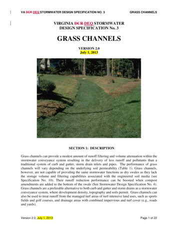
VA DCR DEQ STORMWATER DESIGN SPECIFICATION NO. 3GRASS CHANNELSVIRGINIA DCR DEQ STORMWATERDESIGN SPECIFICATION No. 3GRASS CHANNELSVERSION 2.0July 1, 2013SECTION 1: DESCRIPTIONGrass channels can provide a modest amount of runoff filtering and volume attenuation within thestormwater conveyance system resulting in the delivery of less runoff and pollutants than atraditional system of curb and gutter, storm drain inlets and pipes. The performance of grasschannels will vary depending on the underlying soil permeability (Table 1). Grass channels,however, are not capable of providing the same stormwater functions as dry swales as they lackthe storage volume and filtering capabilities associated with the engineered soil media (seeSpecification No. 10). Their runoff reduction performance can be boosted when compostamendments are added to the bottom of the swale (See Stormwater Design Specification No. 4).Grass channels are a preferable alternative to both curb and gutter and storm drains as a stormwaterconveyance system, where development density, topography and soils permit. Grass channels canalso be used to treat runoff from the managed turf areas of turf-intensive land uses, such as sportsfields and golf courses, and drainage areas with combined impervious and turf cover (e.g., roadsand yards).Version 2.0, July 1, 2013Page 1 of 22
VA DCR DEQ STORMWATER DESIGN SPECIFICATION NO. 3GRASS CHANNELSSECTION 2: PERFORMANCETable 3.1. Summary of Stormwater Functions Provided by Grass Channels 1Stormwater FunctionAnnual Runoff Volume Reduction (RR)Total Phosphorus (TP) EMCReduction4 by BMP TreatmentProcessTotal Phosphorus (TP) Mass LoadRemovalTotal Nitrogen (TN) EMC Reduction4by BMP Treatment ProcessTotal Nitrogen (TN) Mass LoadRemovalChannel & Flood ProtectionHSG Soils A and BWith CANo CA 2NA 320%HSG Soils C and DNo CAWith CA10%20%15%15%32%24% (no CA) to32% (with CA)20%20%36%28% (no CA) to36% (with CA)Partial. Use VRRM Compliance spreadsheet to calculate aCurve Number (CN) adjustment5; OR Design extra storage in the stone underdrain layer andpeak rate control structure (optional, as needed) toaccommodate detention of larger storm volumes.1 CWPand CSN (2008) and CWP (2007).CA Compost Amended Soils, see Stormwater Design Specification No. 4.3 Compost amendments are generally not applicable for A and B soils, although it may be advisable toincorporate them on mass-graded and/or excavated soils to maintain runoff reduction rates. In thesecases, the 30% runoff reduction rate may be claimed, regardless of the pre-construction HSG.4 Change in event mean concentration (EMC) through the practice. Actual nutrient mass load removedis the product of the pollutant removal rate and the runoff volume reduction rate (see Table 1 in theIntroduction to the New Virginia Stormwater Design Specifications).5 NRCS TR-55 Runoff Equations 2-1 thru 2-5 and Figure 2-1 can be used to compute a curve number2Leadership in Energy and Environmental Design (LEED ). The LEED point credit systemdesigned by the U.S. Green Building Council (USGBC) and implemented by the Green BuildingCertification Institute (GBCI) awards points related to site design and stormwater management.Several categories of points are potentially available for new development and redevelopmentprojects. Chapter 6 of the 2013 Virginia Stormwater Management Handbook (2nd Edition)provides a more thorough discussion of the site planning process and design considerations asrelated to Environmental Site Design and potential LEED credits. However, the VirginiaDepartment of Conservation and Recreation (DCR)Environmental Quality is not affiliated withthe USGBC or GBCI and any information on applicable points provided here is based only onbasic compatibility. Designers should research and verify scoring criteria and applicability ofpoints as related to the specific project being considered through USGBC LEED resources.Version 2.0, July 1, 2013Page 2 of 22
VA DCR DEQ STORMWATER DESIGN SPECIFICATION NO. 3GRASS CHANNELSTable 3.2. Potential LEED Credits for Grass Channels1CreditCredit DescriptionNo.Sustainable SitesSS5.2Site Development: Maximize Open SpaceSustainable SitesSS6.1Stormwater Design: Quantity ControlSustainable SitesSS6.2Stormwater Design: Quality Control1 Actual site design and/or BMP configuration may not qualify for the credits listed. Alternatively, theproject may actually qualify for credits not listed here. Designers should consult with a LEED AP.Credit CategorySECTION 3: DESIGN TABLEGrass channels only have one level of design, and must meet the minimum criteria outlined inTable 3.2 to qualify for the indicated level of runoff reduction.Table 3.2. Grass Channel Design GuidanceDesign CriteriaThe bottom width of the channel should be set to maintain the peak flow rate for the 1-inch stormdesign treatment volume (Tv)1 at less than 4 inches in depth and 1 ft/s velocity.The channel side-slopes should be 3H:1V or flatter.The maximum total contributing drainage area to any individual grass channel is 5 acres.The longitudinal slope of the channel should be no greater than 4%. (Check dams may be used toreduce the effective slope in order to meet the limiting velocity requirements.)The dimensions of the channel should ensure that flow velocity is non-erosive during the 2-year and 10year design storm events and the 10-year design flow is contained within the channel (minimum of 0.3feet of freeboard).1 The design of grass channels should consider the entire T of the contributing drainage area (rathervthan the TvBMP which would reflect a decrease in Tv based on upstream runoff reduction practices) inorder to ensure non-erosive conveyance during all design storm conditions.Version 2.0, July 1, 2013Page 3 of 22
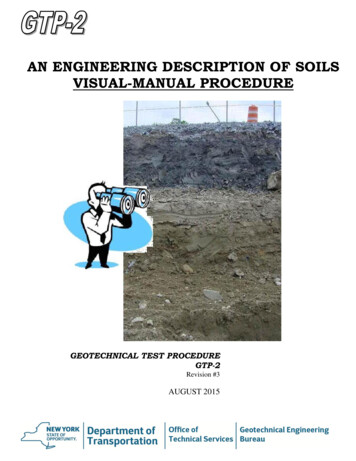
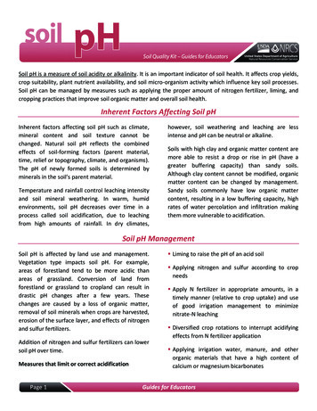
VA DCR DEQ STORMWATER DESIGN SPECIFICATION NO. 3GRASS CHANNELSSECTION 4: TYPICAL DETAILSFigure 3.1. Grass Channel – Typical Plan, Profile and SectionNOTE: NEED ORIGINAL CAD OR OTHER IMAGE – THIS ONE TRUNCATED TOP AND BOTTOMVersion 2.0, July 1, 2013Page 4 of 22
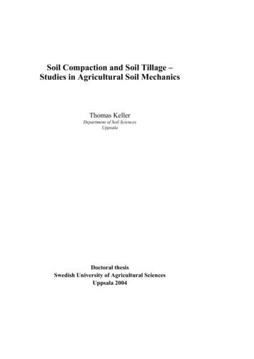
VA DCR DEQ STORMWATER DESIGN SPECIFICATION NO. 3GRASS CHANNELSFigure 3.2 Grass Channel with Check Dams – Typical Plan, Profile, and SectionNOTE: NEED ORIGINAL CAD OR OTHER IMAGE – THIS ONE TRUNCATED TOP AND BOTTOMVersion 2.0, July 1, 2013Page 5 of 22
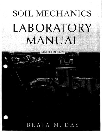
VA DCR DEQ STORMWATER DESIGN SPECIFICATION NO. 3GRASS CHANNELSFigure 3.3: Grass Channel with Compost Amendments - SectionFigure 3.4: Pretreatment I and II - Grass Filter for Sheet FlowVersion 2.0, July 1, 2013Page 6 of 22
VA DCR DEQ STORMWATER DESIGN SPECIFICATION NO. 3GRASS CHANNELSFigure 3.5: Pretreatment – Gravel Diaphragm for Sheet Flow from Impervious or PerviousFigure 3.6: Pre-Treatment – Gravel Flow Spreader for Concentrated FlowVersion 2.0, July 1, 2013Page 7 of 22
VA DCR DEQ STORMWATER DESIGN SPECIFICATION NO. 3GRASS CHANNELSFigure 3.7: Filter Path to Grass ChannelNOTE: NEED ORIGINAL CAD OR OTHER IMAGE – THIS ONE TRUNCATED TOP ANDBOTTOM. ALSO, SECTION LINE ABOVE DOESN’T REFLECT FULL SECTION BELOW.ALSO, RED “SECTION A-A” LINE ON UPPER DRAWING DOES NOT CORRECTLY DEPICTTHE SECTION SHOWN IN THE LOWER DRAWING. IN ORDER TO CORRECT THIS, THE“SECTION A-A” LINE IN THE UPPER DRAWING SHOULD CROSS THE ENTIRE DRAWING.NEED TO FIX THIS.Version 2.0, July 1, 2013Page 8 of 22
VA DCR DEQ STORMWATER DESIGN SPECIFICATION NO. 3GRASS CHANNELSSECTION 5: PHYSICAL FEASIBILITY AND DESIGN APPLICATIONSGrass channels can be implemented on suitable development sites where development density,topography and soils are suitable. The linear nature of grass channels makes them well-suited totreat highway runoff, low and medium density residential road and yard runoff (if there is anadequate right-of-way width and distance between driveways), and small commercial parkingareas or driveways. Grass channels can also provide pre-treatment for other stormwater treatmentpractices.Grass channels are not recommended when residential density exceeds more than 4 dwelling unitsper acre due to a lack of space in the front yards of lots for shallow slopes. Also, frequent drivewaycrossings along the channel create potential maintenance problems.A Dry Swale (Design Specification 10) is an alternative to the Grass Channel and will providegreater performance credit for both runoff volume and pollutant EMC reduction.Key constraints for grass channels include: Land Uses. Grass channels can be used in residential, commercial, or institutional developmentsettings. Residential uses are typically limited to densities of 4 dwelling units per acre in orderto avoid safety and nuisance conditions.Large commercial site applications may require multiple channels in order to effectively breakup the drainage areas and meet the design criteria.The linear nature of grass channels makes them well suited to treat highway or low- andmedium-density residential road runoff, if there is adequate right-of-way width and distancebetween driveways.Grass channels can be used to treat the managed turf areas of sports fields, golf courses, andother turf-intensive land uses, or to treat drainage areas with both impervious and managed turfcover (such as residential streets and yards), as long as drainage area limitations and designcriteria can be met.Contributing Drainage Area. The maximum contributing drainage area to a grass channel shouldbe 5 acres, and preferably less. When grass channels treat and convey runoff from drainage areasgreater than 5 acres, the velocity and flow depth through the channel becomes too great to treatrunoff or prevent erosion in the channel. The design criteria for maximum channel velocity anddepth are applied along the entire length, and must meet regulatory requirements (4 VAC 50-6066) at the downstream limit.Available Space. Grass channels can be incorporated into linear development applications (e.g.,roadways) by utilizing the footprint typically required for an open section drainage feature. Thefootprint required will likely be greater than that of a typical conveyance channel (VDOT orequivalent). However, the benefit of the runoff reduction may reduce the footprint requirementsfor stormwater management elsewhere on the development site.Version 2.0, July 1, 2013Page 9 of 22
VA DCR DEQ STORMWATER DESIGN SPECIFICATION NO. 3GRASS CHANNELSChannel Configuration. Grass channels are especially suited for both conveyance and waterquality treatment when applied in linear configurations parallel to the contributing imperviouscover, with runoff entering as sheet flow, such as roads and small parking areas.Longitudinal Slope. Grass channels are limited to longitudinal slopes of less than 4%. However,the limiting velocity requirements will typically require check dams to reduce the effective slope.Slopes steeper than 4% create rapid runoff velocities that can cause erosion and do not allowenough contact time for infiltration or filtering, unless check dams are used.Longitudinal slopes of less than 2% are ideal and may eliminate the need for check dams. However,channels designed with longitudinal slopes of less than 1% should be monitored carefully duringconstruction to ensure a continuous grade along the entire length of the channel, in order to avoidflat areas with pockets of standing water.Soils. Grass channels can be used on sites with any type of soils. However, grass channels situatedon Hydrologic Soil Group C and D soils will require soil amendments in order to improveperformance, as noted in Table 3.1 (Stormwater Design Specification No. 4, Soil CompostAmendment).Hydraulic Capacity. Grass channels can be designed as an off-line practice, however they aretypically an on-line practice and as such must be designed with enough capacity to convey runofffrom the 10-year design storm event within the channel banks and be non-erosive during both the2-year and 10-year design storm events. This means that the much of the surface dimensions aredriven by the need to pass these larger storm events.Depth to Water Table. Designers should ensure that the bottom of the grass channel does notintercept the seasonally high water table to ensure that the channel remains dry between stormevents.Utilities. Designers should consult local utility design guidance for the horizontal and verticalclearance between utilities and the channels. Typically, utilities can cross grass channels if theyare specially protected (e.g., double-casing) or are located below the channel invert.Hotspot Land Uses. Grass channels are not recommended to treat stormwater hotspots, due to thepotential for infiltration of hydrocarbons, trace metals and other toxic pollutants into groundwater.For a list of typical stormwater hotspots, see Stormwater Design Specification No. 8 (Infiltration).Minimum Setbacks. Local ordinances and design criteria should be consulted to determineminimum setbacks from property lines, structures, utilities, and wells. As a general rule, grasschannels should be set back at least 10 feet from building foundations, 35 feet from septic systemfields and 50 feet from private wells.Version 2.0, July 1, 2013Page 10 of 22
VA DCR DEQ STORMWATER DESIGN SPECIFICATION NO. 3GRASS CHANNELSSECTION 6: DESIGN CRITERIA6.1. Sizing of Grass ChannelsUnlike other stormwater practices, grass channels are designed based on a peak rate of flow.Designers must demonstrate channel conveyance and treatment capacity in accordance with thefollowing guidelines: The longitudinal slope of the channel should ideally be between 1% and 2% in order to avoidscour and short-circuiting within the channel. Longitudinal slopes up to 4% are acceptable;however, check dams will likely be required in order to meet the allowable maximum flowvelocities.Hydraulic capacity should be verified using Manning’s Equation or an accepted equivalentmethod, such as erodibility factors and vegetal retardance (NOVA 2007).o The flow depth for the Tv peak flow (1-inch rainfall) should be maintained at 4 inches orless.o Manning’s “n” value for grass channels should be 0.2 for flow depths up to 4 inches,decreasing to 0.03 at a depth of 12 inches (which would apply to the 2-year and 10-yearstorms if an on-line application – NOVA, 2007; Haan et. al, 1994).o Peak Flow Rates for the 2-year and 10-year frequency storms must be non-erosive, inaccordance with Table 3.3, or subject to a site-specific analysis of the channel liningmaterial and vegetation; and the 10-year peak flow rate must be contained within thechannel banks (with a minimum of 4 inches of freeboard).Calculations for peak flow depth and velocity should reflect any increase in flow along thelength of the channel, as appropriate. If a single flow is used, the flow at the outlet should beused.The hydraulic residence time (the time for runoff to travel the full length of the channel) shouldbe a minimum of 9 minutes for the Tv (1-inch rainfall) design storm (Spyridakis, Mar, andHorner, 1982; Keblin, Walsh, Malina, and Charbeneau, 1998; Washington State Departmentof Ecology, 2005). If flow enters the swale at several locations, a 9 minute minimum hydraulicresidence time should be demonstrated for each entry point, using Equations 3.1 and 3.2 below(Equations 5-1 and 5-2, NOVA 2007).The minimum length or residence time may be achieved with multiple swale segmentsconnected by culverts with energy dissipaters.The bottom width of the grass channel is therefore sized to maintain the appropriate flow geometryas follows:Equation 3.1: Manning’s EquationWhere:V n D s 1.49 2 3 1 2 𝐷𝐷 𝑠𝑠 𝑉𝑉 𝑛𝑛flow velocity (ft./sec.)roughness coefficient (0.2, or as appropriate)flow depth (ft.) (NOTE: D approximates hydraulic radius for shallow flows)channel slope (ft./ft.)Version 2.0, July 1, 2013Page 11 of 22
VA DCR DEQ STORMWATER DESIGN SPECIFICATION NO. 3GRASS CHANNELSEquation 3.2: Continuity Equation𝑞𝑞𝑝𝑝𝑝𝑝𝑝𝑝 𝑉𝑉𝑉𝑉 𝑉𝑉(𝑊𝑊 𝐷𝐷)Where:𝑞𝑞𝑝𝑝𝑝𝑝𝑝𝑝 design Tv peak flow rate (cfs) (Section 11.5.3 of Chapter 11 of the VirginiaStormwater Management Handbook (2nd Edition, 2013)A flow cross sectional area (ft2)V design flow velocity (ft./sec.)W channel width (ft.)D flow depth (ft.)(NOTE: channel width (W) x depth (D) approximates the cross sectional flow area forshallow flows.)Combining Equations 3.1 and 3.2, and re-writing them provides a solution for the minimum width:Equation 3.3: Minimum Width𝑊𝑊 (𝑛𝑛) 𝑞𝑞𝑝𝑝𝑝𝑝𝑝𝑝 1.49𝐷𝐷5 3 𝑠𝑠 1 2 Solving Equation 3.2 for the corresponding velocity provides:Equation 3.4: Corresponding Velocity𝑉𝑉 𝑞𝑞𝑝𝑝𝑝𝑝𝑝𝑝 (𝑊𝑊 𝐷𝐷)The resulting velocity should be less than 1 ft./sec. The width, slope, or Manning’s “n” value canbe adjusted to provide an appropriate channel design for the site conditions. However, if a higherdensity of grass is used to increase the Manning’s “n” value and decrease the resulting channelwidth, it is important to provide material specifications and construction oversight to ensure thatthe denser vegetation is actually established. Equation 3.5 can then be used to ensure adequatehydraulic residence time.Equation 3.5: Grass Channel Length for HydraulicResidence Time of 9 minutes (540 seconds)L 540VWhere:L minimum swale length (ft.)V flow velocity (ft./sec.)Version 2.0, July 1, 2013Page 12 of 22
VA DCR DEQ STORMWATER DESIGN SPECIFICATION NO. 3GRASS CHANNELSTable 3.3: Maximum Permissible Velocities for Grass ChannelsCover TypeBermudagrassKentucky bluegrassReed CanarygrassTall fescueBermudagrassKentucky bluegrassReed CanarygrassTall fescueGrass-legume mixture0–5ErosionResistant Soils(ft./sec.)60–553.85 – 1053.85 – 10430–55 - 104332.3Slope (%)Easily ErodedSoils (ft./sec.)4.5Kentucky bluegrassReed Canarygrass 1032.3Tall fescueRed fescue0-52.51.9Sources: Virginia E&S Control Handbook, 1992; Ree, 1949; Temple et al, 1987; NOVA, 20076.2. Geometry and Site Layout Grass channels should generally be aligned adjacent to and the same length (minimum) as thecontributing drainage area identified for treatment.Grass channels should be designed with a trapezoidal or parabolic cross section. A parabolicshape is preferred for aesthetic, maintenance and hydraulic reasons.The bottom width of the channel should be between 4 to 8 feet wide. If a channel will be widerthan 8 feet, the designer should incorporate benches, check dams, level spreaders or multilevel cross sections to prevent braiding and erosion along the channel bottom.Grass channel side slopes should be no steeper than 4H:1V for ease of mowing and routinemaintenance. Flatter slopes are encouraged, where adequate space is available, to aid in pretreatment of sheet flows entering the channel. Under no circumstances are side slopes to exceed3H:1V.6.3. PretreatmentPretreatment is recommended for grass channels to dissipate energy, trap sediments and slow downthe runoff velocity. The selection of a pre-treatment method depends on whether the channel willexperience sheet flow or concentrated flow. Several reliable options are as follows: Check dam forebays (channel flow): The most common form of pre-treatment at concentratedinflow points is a forebay formed by a check dam.Tree Check dams (channel flow): These are street tree mounds that are placed within thebottom of grass channels up to an elevation of 9 to 12 inches above the channel invert. Oneside has a gravel or river stone bypass to allow runoff to percolate through (Cappiella et al,2006).Grass Filter Strip (sheet flow): Grass filter strips extend from the edge of the pavement to thebottom of the grass channel at a slope of 5:1 or less. Alternatively, provide a combined 5 feetVersion 2.0, July 1, 2013Page 13 of 22
VA DCR DEQ STORMWATER DESIGN SPECIFICATION NO. 3 GRASS CHANNELSof grass filter strip at a maximum 5% (20:1) cross slope and 3:1 or flatter side slopes on thegrass channel.Gravel or Stone Diaphragm (sheet flow): The gravel diaphragm is located at the edge of thepavement or the edge of the roadway shoulder and extends the length of the channel to pretreat lateral runoff. This requires a 2 to 4 inch elevation drop from a hard-edged surface into agravel or stone diaphragm.Gravel or Stone Flow Spreaders (concentrated flow). The gravel flow spreader is located atcurb cuts, downspouts, or other concentrated inflow points, and should have a 2 to 4 inchelevation drop from a hard-edged surface into a gravel or stone diaphragm. The gravel shouldextend the entire width of the opening and create a level stone weir at the bottom or treatmentelevation of the channel.6.4. Check damsCheck dams may be used for pre-treatment, to reduce the effective longitudinal slope, and toincrease the hydraulic residence time in the channel. Design requirements for check dams are asfollows: Check dams should be spaced based on the channel slope, as needed to increase residence time,provide Tv storage volume, or any additional volume attenuation requirements. The pondedwater at a downhill check dam should not touch the toe of the upstream check dam.The maximum desired check dam height is 12 inches (for maintenance purposes). The averageponding depth throughout the channel should be 12 inches.Armoring may be needed at the downstream toe of the check dam to prevent erosion.Check dams must be firmly anchored into the side-slopes to prevent outflanking; check damsmust also be anchored into the channel bottom a minimum of 6 inches so as to preventhydrostatic head from pushing out the underlying soils.Check dams must be designed with a center weir sized to pass the channel design storm peakflow (10-year storm event if an on-line practice).The check dam should be designed so that it facilitates easy mowing (gravel check dams arediscouraged for this reason).Each check dam should have a weep hole or similar drainage feature so it can dewater afterstorms.Check dams should be composed of wood, concrete, stone, or other non-erodible material, orbe should be configured with elevated driveway culverts.Individual channel segments formed by check dams or driveways should generally be at least25 to 40 feet in length.6.5. Compost Soil AmendmentsSoil compost amendments serve to increase the runoff reduction capability of a grass channel. Thefollowing design criteria apply when compost amendments are used: The compost-amended strip should extend over the length and width of the channel bottom,and the compost should be incorporated to a depth as outlined in Stormwater DesignSpecification No. 4, Soil Compost Amendment.Version 2.0, July 1, 2013Page 14 of 22
VA DCR DEQ STORMWATER DESIGN SPECIFICATION NO. 3 GRASS CHANNELSThe amended area will need to be rapidly stabilized with perennial, salt tolerant grass species.For grass channels on steep slopes, it may be necessary to install a protective biodegradablegeotextile fabric to protect the compost-amended soils. Care must be taken to consider theerosive characteristics of the amended soils when selecting an appropriate geotextile.For redevelopment or retrofit applications, the final elevation of the grass channel (followingcompost amendment) must be verified as meeting the original design hydraulic capacity.6.6. Planting Grass ChannelsDesigners should choose grass species that can withstand both wet and dry periods as well asrelatively high-velocity flows within the channel. For applications along roads and parking lots,salt tolerant species should be chosen. Taller and denser grasses are preferable, though the speciesof grass is less important than good stabilization. For a list of grass species suitable for use in grasschannels, consult the Virginia Erosion Control Handbook.Grass channels should be seeded at such a density to achieve a 90 % turf cover after the secondgrowing season. Grass channels should be seeded and not sodded. Seeding establishes deeper rootsand sod may have muck soil that is not conducive to infiltration (Wisconsin DNR, 2007). Grasschannels should be protected by a biodegradable erosion control fabric to provide immediatestabilization of the channel bed and banks.6.7. Grass Channel Material SpecificationsThe basic material specifications for grass channels are outlined in Table 3.4 below.ComponentGrassCheck DamsDiaphragmErosion ControlFabricFilter Fabric(check dams)Table 3.4. Grass Channel Materials SpecificationsSpecificationA dense cover of water-tolerant, erosion-resistant grass. The selection of anappropriate species or mixture of species is based on several factors includingclimate, soil type, topography, and sun or shade tolerance. Grass species shouldhave the following characteristics: a deep root system to resist scouring; a high stemdensity with well-branched top growth; water-tolerance; resistance to being flattenedby runoff; an ability to recover growth following inundation; and, if receiving runofffrom roadways, salt-tolerance. Check dams should be constructed of a non-erosive material such as wood,gabions, riprap, or concrete. All check dams should be underlain with filter fabricconforming to local design standards. Wood used for check dams should consist of pressure treated logs or timbers,or water-resistant tree species such as cedar, hemlock, swamp oak or locust.Pea gravel used to construct pre-treatment diaphragms should consist of washed,open-graded, course aggregate between 3 and 10 mm in diameter and mustconform to local design standards.Where flow velocities dictate, biodegradable erosion control netting or mats that aredurable enough to last at least two growing seasons must be used, conforming toVDOT EC3.Filter fabric is applicable in several different capacities when construction a grasschannel with check dams and/or rip rap, etc. Designers should select an appropriatefilter fabric for the particular application based on AASHTO M288-06SECTION 7: REGIONAL & SPECIAL CASE DESIGN ADAPTATIONSVersion 2.0, July 1, 2013Page 15 of 22
VA DCR DEQ STORMWATER DESIGN SPECIFICATION NO. 3GRASS CHANNELS7.1. Karst TerrainGrass channels are an acceptable practice in karst terrain, as long as they do not treat hotspotrunoff. The following design adaptations apply to grass channels in karst terrain: Soil compost amendments may be incorporated into the bottom of grass channels to improvetheir runoff reduction capability, as noted in Table 3.1 above.Check dams are generally discouraged for grass swales in karst terrain, since they pond toomuch water (although flow spreaders that are flush with the ground surface and spaced alongthe channel length may be useful in spreading flows more evenly across the channel width).The minimum depth to the bedrock layer is 18 inches.A minimum slope of 0.5% must be maintained to ensure positive drainage.The grass channel may have off-line cells and should be tied into an adequate discharge point.7.2. Coastal PlainAlthough grass channels work reasonably well in the flat terrain and low head conditions of manycoastal plain sites, they have very poor nutrient and bacteria removal rates, and should not be usedas a stand-alone treatment system. Dry swales or wet swales are much superior options to the grasschannel, unless the soils are in the highly permeable HSG “A” group. Where HSG-A soils occur: The minimum depth from the swale invert to the seasonally high water table should be 12inches.A minimum slope of 0.5% must be maintained to ensure positive drainage.The grass channel may have off-line cells and should be tied into the ditch system7.3. Steep TerrainGrass swales are not practical in areas of steep terrain, although terracing a series of grass swalecells may work on slopes from 5% to 10%. The drop in elevation between check dams should belimited to 18 inches in these cases, and the check dams should be armored on the down-slope sidewith suitably sized stone to prevent erosion.7.4. Cold Climate and Winter PerformanceGrass swales can store snow and treat snowmelt runoff when they serve road or parking lotdrainage. If roadway salt is applied in their CDA, grass swales should be planted with salt-tolerantspecies. Consult the Minnesota Stormwater Manual for a list of salt-tolerant grass species (MSSC,2005).7.5. Linear Highway SitesGrass swales are a preferred stormwater practice for linear highway sites.Version 2.0, July 1, 2013Page 16 of 22
VA DCR DEQ STORMWATER DESIGN SPECIFICATION NO. 3GRASS CHANNELSSECTION 8: CONSTRUCTION8.1. Construction SequenceThe following is a typical construction sequence to properly install a grass channel, although stepsmay be modified to reflect different site conditions. Grass channels should be installed at a timeof year that is best to establish turf cover without irrigation. Some local agencies restrict plantingto the following periods of time: February 15 through April 15 and September 15 throughNovember 15.Step 1: Protection during Site Construction. Ideally, grass channels should remain outside thelimit of disturbance during construction to prevent soil compaction by heavy equipment. However,this is seldom practical, given that the channels are a key part of the drainage system at most sites.In these cases, temporary E&S controls such as dikes, silt fences and other erosion controlmeasures should be integrated into the swale design throughout the construction sequence.Specifically, barriers should be installed at key check dam locations, and erosion control fabricshould be used to protect the channel.Step 2. Grass channel installation may only begin after the entire contributing drainage area hasbeen stabilized with vegetation. Any accumulation of sediments that does occur within the channelmust be removed during the final stages of grading to achieve the design cross-section. Erosionand sediment controls for construction of the grass channel should be installed as specified in theerosion and sediment control plan. Stormwater flows must not be permitted into the grass channeluntil the bottom and side slopes are fully stabilized.Step 3. Grade the grass channel to the final dimensions shown on the plan.Step 4. Install check dams, driveway culverts and internal pre-treatment features as shown on theplan. The top of each check dam should be constru
VA DCR DEQ STORMWATER DESIGN SPECIFICATION NO. 3 GRASS CHANNELS Version 2.0, July 1, 2013 Page 2 of 22 SECTION 2: PERFORMANCE . Table 3.1. Summary of Stormwater Functions Provided by Grass Channels 1. Stormwater Function HSG Soils A and B HSG Soils C and D No CA 2 With CA No CA With CA Annual Runoff Volume Reduction (RR) 20% NA 3 10% 20%