Transcription
Soil Compaction and Soil Tillage –Studies in Agricultural Soil MechanicsThomas KellerDepartment of Soil SciencesUppsalaDoctoral thesisSwedish University of Agricultural SciencesUppsala 20041
Acta Universitatis Agriculturae SueciaeAgraria 489ISSN 1401-6249ISBN 91-576-6769-1 2004 Thomas Keller, UppsalaTryck: SLU Service/Repro, Uppsala 20042
AbstractKeller, T. 2004. Soil Compaction and Soil Tillage - Studies in Agricultural Soil MechanicsDoctoral dissertation.ISSN 1401-6249, ISBN 91-576-6769-1This thesis deals with various aspects of soil compaction due to agricultural field traffic, thedraught force requirement of tillage implements and soil structures produced by tillage.Several field experiments were carried out to study the mechanical impact of agriculturalmachines. It was shown that the stress interaction from the different wheels in dual andtandem wheel configurations is small and these wheels can be considered separate wheelswith regard to soil stress. Hence, soil stress is not related to either axle load or total vehicleload. At high wheel load, tyre inflation pressure affected subsoil stresses. The maximumstress at the soil-tyre interface was greater than the tyre inflation pressure. Furthermore, thedistribution of stress beneath tyres and rubber belts was highly non-uniform. This wasshown to have a great influence on stress propagation in soil. Therefore, with regard to soilcompaction modelling, a uniform stress distribution (as often used) is too poor anapproximation of the real stress distribution and can result in underestimation of soilcompaction. A model for predicting the distribution of stress below tyres using readilyavailable tyre parameters is proposed. With a more realistic approximation of the stressdistribution at the soil surface, simulated stresses generally agreed well with measuredstresses.Both field and laboratory measurements rejected the concept of precompression stress asa distinct threshold value between reversible and irreversible compressive strain.Irreversible strain was measured at applied stresses that were lower than theprecompression stress. The precompression stress was dependent on the nature of thecompression test and the method of analysis.The draught requirement of tillage implements could be related to shear vane strength forspecific soil-implement combinations. Draught force and aggregate size distributionproduced by tillage were strongly affected by soil water content, with the optimum tillageresults being produced at water contents close to the water content at the inflection point ofthe water retention curve. Specific draught was calculated for comparison of the tillageefficiency of different implements. The chisel plough often worked below its critical depth,which strongly increased the energy requirement without any benefit in terms of soil breakup. Therefore, the specific draught was higher for the chisel plough compared with the discharrow and the mouldboard plough.Keywords: aggregates, draught force, model, precompression stress, soil compaction, soildisplacement, soil strength, soil stress, soil water, tillage.Author’s address: Thomas Keller, Department of Soil Sciences, SLU, P.O. Box 7014, SE750 07 Uppsala, Sweden. E-mail: thomas.keller@mv.slu.se3
” doch d’Wält isch so perfid, dass si sech sälten oder nie nachBilder, wo mir vo’re gmacht hei, richtet ”Mani Matter in Chue am Waldrand”.but the world is so perfidious that it rarely or never acts in accordance withpictures that we’ve made of it ”Mani Matter in Cow at the Edge of the Woods4
ContentsIntroduction9Objectives10Some definitions12Methodological aspectsExperimental sites and machine propertiesWheeling experiments: measurements of stress and displacement141414Do transducers provide accurate estimates of the true stresses in soil?Methods to measure soil displacementMeasurements of draught forceMethods to measure draught forceStress propagation in soilTheoretical backgroundStress state in soilModelling stress propagation in soilMeasurements and simulations of stress in soil due to agriculturalfield traffic151617181919192022Distribution of stress at the tyre/track-soil interfaceMeasurements and simulations of stress propagation in soil2225Mechanical behaviour of soilCompressive behaviour of soil – soil precompression stress2828Influence of compression test, determination method and samplesize on precompression stressSome remarks on the use of the logarithm of applied stress forexpressing the compressive behaviour of soilSoil behaviour during wheeling in relation to precompression stressShear strength, tensile strength and penetrometer resistanceImpact of soil type and soil conditions on mechanical propertiesModelling stress-strain relationshipsCompressive behaviour of soilCritical state soil mechanicsImpacts of agricultural field traffic on soil propertiesSoil compaction modellingLimitations of the different model approachesSoilFlex – A Soil compaction model that is Flexible3133343940414142434546475
Soil tillageTillage implementsSoil break-up and implement performanceDraught force requirement and specific resistancePredicting draught forceFriability and workabilityOptimum water content for tillage49495052555757Interactions between tillage operations and soil compactionEffect of compaction on draught requirementEffect of draught force on soil stress and soil propertiesEffect of compaction on workability and friability60606162Practical solutions to reduce the risk of subsoil compaction63Conclusions and implications for future research65References67Acknowledgements746
AppendixPapers I-VIIIThis thesis is based on the following papers, which are referred to in the text bytheir Roman numerals:IArvidsson, J. & Keller, T. 2004. Soil precompression stress. I. Asurvey of Swedish arable soils. Soil & Tillage Research 77(1), 85-95.IIKeller, T., Arvidsson, J., Dawidowski, J.B. & Koolen, A.J. 2004.Soil precompression stress. II. A comparison of different compactiontests and stress-displacement behaviour of the soil during wheeling.Soil & Tillage Research 77(1), 97-108.IIIKeller, T., Trautner, A. & Arvidsson, J., 2002. Stress distribution andsoil displacement under a rubber-tracked and a wheeled tractorduring ploughing, both on-land and within furrows. Soil & TillageResearch 68(1), 39-47.IVKeller, T. & Arvidsson, J., 2004. Technical solutions to reduce therisk of subsoil compaction: Effects of dual wheels, tandem wheelsand tyre inflation pressure on stress propagation in soil. Special issueof Soil & Tillage Research on Soil Physical Quality. In pressVKeller, T. A model for prediction of the contact area and thedistribution of vertical stress below agricultural tyres from readilyavailable tyre parameters. Submitted to Biosystems EngineeringVIKeller, T., Défossez, P., Weisskopf, P., Arvidsson, J. & Richard, G.SoilFlex: A model for prediction of soil stresses and soil compactiondue to agricultural field traffic including a synthesis of analyticalapproaches. ManuscriptVIIArvidsson, J., Keller, T. & Gustafsson, K., 2004. Specific draughtfor mouldboard plough, chisel plough and disc harrow at differentwater contents. Special issue of Soil & Tillage Research on SoilPhysical Quality. In pressVIIIKeller, T., Arvidsson, J. & Dexter, A.R. Soil structures produced bytillage as affected by soil water content and the physical quality ofsoil. ManuscriptReprints are published with permission of Elsevier Science B.V.8
7
IntroductionSoil degradation is a subject that is attracting increasing concern worldwide. TheEuropean Union has realised that there is a need to protect soils and has identifiedsoil compaction as one of the main threats to soil that may result in the degradationof soils (COM, 2002).Reasons for the increasing soil degradation due to soil compaction may be foundin the increase in weight of agricultural machinery, in the more intense use ofmachinery even under unfavourable soil conditions and in bad crop rotations.Economic pressure and structural changes in modern agriculture may contribute tothis development.Soil compaction is an environmental problem (Pagliai et al., 2004). It is one ofthe causes of erosion and flooding (Horn et al., 1995; Soane & Ouwerkerk, 1995;Gieska et al., 2003). In addition, it directly or indirectly increases nutrient andpesticide leaching to the groundwater and nitrous oxide (a greenhouse gas)emissions to the atmosphere (Lipiec & Stepniewski, 1995).From an agronomic point of view, the consequences of soil compaction aredecreased root growth and plant development, and consequently, a reduction incrop yield (Håkansson & Reeder, 1994). Subsoil compaction may persist for avery long time and is hence a threat to the long-term productivity of the soil (Etana& Håkansson, 1994).Efforts to ameliorate compacted subsoil by mechanical deep-loosening areexpensive and often fail. Therefore, soil compaction must be prevented. It isbelieved that the risk of undesirable changes in soil structure can be minimised bylimiting the mechanically-applied stress to below a threshold stress (Dawidowskiet al., 2001), termed the precompression stress. While the concept ofprecompression stress as a threshold between reversible and irreversible strain(Horn & Lebert, 1994) is widely used, it has been scarcely tested in combinationwith wheeling experiments in the field. The impact of agricultural machinery onsoil properties may be simulated by means of soil compaction models, which arean important tool for developing strategies for prevention of soil compaction.Due to compaction, the soil not only becomes denser, but also stronger.Consequently, the soil is more difficult to till and its friability (i.e. ability tofragment) is decreased. As an effect of the stronger soil, draught requirement andtherefore fuel consumption for tillage are increased; this increases the release ofgreenhouse gases that may contribute to global warming. The increased energyrequirement also negatively influences the farmer’s budget: the costs for fuel arehigh compared with the income from yield, and therefore, it is very important tominimise costs for tillage in order to optimise profit. The amount of energyconsumption in tillage (especially in primary tillage) is quite high compared withother farming operations (Gill & Vandenberg, 1968; Shrestha et al., 2001).Therefore, it is interesting to study the energy requirement for different tillageimplements on different soils and at different soil conditions, and to comparedifferent tillage systems.9
In order to minimise the number of tillage operations and therefore total energyinput for a given tillage system, tillage should be performed at optimal soilconditions. The soil structures produced by tillage are strongly affected by soilmoisture. There exists a water content at which the result of tillage is optimum (i.e.the proportion of small aggregates produced is largest or, conversely, theproportion of clods produced smallest), termed the optimum water content fortillage. Dexter & Birkás (2004) showed that the proportion of clods produced bytillage at the optimum water content is larger for soils with lower soil physicalquality, i.e. for degraded soils. Not only is the result of tillage worse for adegraded soil, but also the number of workable days is smaller compared with asoil of good physical quality (Dexter & Bird, 2001).Prevention of soil compaction is a most significant measure in order to sustainor improve soil physical quality. Good soil physical quality implies good soilworkability, which is a pre-condition for minimising (energy use in) soil tillage.ObjectivesThe objectives of this thesis were:(a) Soil precompression stress and its practical significance foragricultural soil mechanics: To compare the precompression stressesobtained by different tests and different determination procedures; tostudy the stress-strain behaviour of soil in the field during agriculturalfield traffic and relate that to the precompression stress(b) Stress distribution at the soil-tyre/track interface and stresspropagation in soil: To measure the distribution of stress in the groundcontact area and the stress propagation in soil caused by differentmachines and during different field operations, and to comparemeasurements with model simulations(c) Draught requirement of different tillage implements during primarytillage: To measure the draught requirement of different implements ondifferent soils and at different water contents(d) Optimal water content for primary tillage: To measure aggregate sizedistribution produced by tillage as influenced by tillage implement, soiltype and soil moisture content10
The following chapters contain an overview of the subject of soil compaction andtillage and put the research carried out in the present study into context. Theresults presented are mainly summarised from Papers I-VIII, but some are solelypublished in the following chapters.The first chapter gives definitions of some technical terms to facilitate thereading of this thesis. The second chapter deals with methodological aspects andbriefly describes and discusses the main features of the methods used during fieldexperiments to give the reader an overview. This is followed by chapters on stresspropagation and mechanical behaviour of soil, which include a general discussionof stress measurements and simulations and a detailed discussion of soilprecompression stress and some aspects of soil compaction modelling. The nextchapter is on soil tillage including soil break-up, draught force requirement andfriability. It is followed by a chapter on interactions between tillage andcompaction. Finally, there is a chapter on practical solutions to reduce the risk ofsoil compaction. The conclusions include implications for future research.11
Some definitionsBulk density, ρρ total soil masstotal soil volumeCompaction orcompressionReduction of the volume of a given mass of soil, i.e.decrease in void ratio and porosity and, conversely,increase in bulk density.Pure compaction: the shape of a soil volumeremains unchanged.ConsolidationCompaction through the drainage of water.Dilation,expansion orlooseningIncrease in volume of a given mass of soil, i.e.increase in void ratio and porosity and, conversely,decrease in bulk density.Porosity, ηη volume of water and airtotal soil volumePrecompression stress,precompaction stress,preconsolidation stress orpreloadLargest overburden stress to which a soil has beenexposed.Referred to as a threshold stress such that loadingsinducing smaller stresses than this threshold causelittle additional compaction, and loadings inducinggreater stresses cause much additional compaction.PressureForce or thrust exerted over a surface divided by thearea of the surface. Pressure is a scalar, i.e. it isindependent of direction.Unit: 1 Pa 1 N m-2; 1 bar 100 kPa;1atm 1kp cm-2 100 kPa; 1 psi lb in-2Shear deformationChange in the shape of a soil volume.Pure shear deformation or distortion:deformation at constant volume.Specific volume, v12v total soil volumevolume of solids 1 eshear
StrainMeasure of the deformation of a body. Strains caninvolve changes in volume, shape or both. u x x1 u y u x 2 x y Normal strain, ε xx Shear strain, ε xy u Engineering shear strain, γ xy y u x x y StrengthStress at which a material fails; therefore, strengthhas the same units as stress.StressForce per unit area. Stress is a vector, i.e. it acts in acertain direction.Unit: 1 Pa 1 N m-2A stress acting perpendicular to a plane is called anormal stress; a stress acting tangential to a plane iscalled a shear stress.Note: In soil science, compressive stresses areusually defined as positive and tensile stresses asnegative; in geotechnical engineering, compressivestresses are usually defined as negative and tensilestresses as positive.TensionThe act or action of stretching; contrasted withcompressive stress.Tensile strength: Resistance to rupture undertension, i.e. the greatest tensile stress a material canbear without tearing apart.Void ratio, ee volume of voidsvolume of solids η v 11 η13
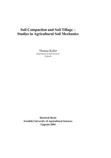
Methodological aspectsExperimental sites and machine propertiesWheeling experiments were carried out in Sweden at Billeberga (55.9 N, 13.0 E),Önnestad (56.1 N, 14.0 E), Örsundsbro (59.7 N, 17.3 E), Strängnäs (59.4 N,17.0 E), Uppsala (59.9 N, 17.6 E), Varberg (57.1 N, 12.3 E) and Tolefors(58.4 N, 15.6 E) and in Denmark at Krenkerup (54.8 N, 11.6 E) and Vallø(55.4 N, 12.1 E) in the years 2000 to 2004. The texture of the soils ranged fromsandy loam to clay. Wheeling experiments were carried out with towed trailers,wheeled and tracked tractors and sugar beet harvesters. The wheel loads were inthe range 11 to 125 kN.Tillage experiments were carried out at Ultuna and Säby in Uppsala during theyears 2001 to 2003. The texture of the soils ranged from sandy loam to clay.Draught force and aggregate size distribution produced by tillage were measuredfor autumn primary tillage operations. The implements used were mouldboardplough, chisel plough and disc harrow.Wheeling experiments: measurements of stress and displacementThe distribution of the vertical stress below the ground contact area of tyres (ortracks) was measured by (usually) five stress sensors that were buried in thetopsoil at 0.1 m depth. Each sensor (DS Europe Series BC 302) was attached to analuminium disc (diameter: 17.5 mm, height: 5.5 mm) embedded in the centre of alarger aluminium disc (diameter: 70 mm, height: 15 mm), see Fig. 1(a). The cellswere placed on a line perpendicular to the driving direction under one half of thewheel track [Fig. 1(b)]. One cell was placed below the centre of the tyre, onebelow the edge of the tyre, and the remaining cells were placed in between. Theset-up was similar for tracks.Fig. 1. (a) Stress sensor for measurements below the tyre; (b) sketch of stress measurementsbelow the tyre (plane view).14
Fig. 2. (a) Experimental set-up for stress and displacement measurements in the subsoil; (b)probe for subsoil measurements.Vertical soil stress and displacement were measured by installing probes into thesoil horizontally from a dug pit that was approximately 1.5 m long, 1 m wide and1m deep, with the walls stabilized with wooden boards [Fig. 2(a)]. The probeswere installed through drilled holes that were stabilized by inserting a steel tubehaving the same diameter (58 mm) as the hole. For each wheeling pass, threeprobes were installed, typically at 0.3, 0.5 and 0.7 m depth. The distance betweenthe pit wall and the probe head was approximately 1.1 m [Fig. 2(a)]. Stress wasmeasured by a load cell (DS Europe Series BC 302) with a diameter of 17.5 mm[Fig. 2(b)]. Determination of the displacement is based on the physical principlethat the pressure of a column of liquid (in this case silicone oil) is proportional toits height (Fig. 2). The method is described in detail in Arvidsson & Andersson(1997).Do transducers provide accurate estimates of the true stresses in soil?In this thesis, vertical stress was measured by load cells, also referred to as verticaltransducers. Vertical transducers were also used by e.g. Blunden et al. (1994) andKirby et al. (1997). Measuring only vertical stress may be a serious limitation,since it is not only vertical stresses that are of importance for soil reaction in termsof soil deformation and soil compaction, but also horizontal stresses and shearstresses. Several researchers including Bailey et al. (1988), Bakker et al. (1995),Way et al. (1995), Wiermann et al. (1999), Pytka & Dabrowski (2001), AbuHamdeh & Reeder (2003) and Horn et al. (2003) measured stresses with atransducer with six measuring faces; such a transducer is called a stress statetransducer. Gysi et al. (1999), Gysi et al. (2000) and Diserens & Steinmann(2002), measured soil stress with Bolling pressure probes (Bolling, 1987). Gysi etal. (2000) showed that the stress measured by Bolling probes is a good indicatorof the mean normal stress.Measuring stress in soil with stress transducers is accompanied by severalproblems, as discussed by Trautner (2003). A pre-condition for reliable stressmeasurements is to have a good contact between the stress transducer and thesurrounding soil. This may be difficult, especially under very dry conditions or insandy soils (Trautner, 2003). Obtaining good contact between transducer and soil15
is probably more difficult with a stress state transducer (with six faces) than with avertical transducer (with one face).The stress estimate provided by the transducer is influenced by the stiffness ofthe transducer in comparison with its surrounding soil (Kirby, 1999a, b). The sizeof the transducer is another factor affecting the measurements. Trautner (2003)observed that the measured stress was much higher when the stress sensors wereplaced on a wooden board compared with when the stress sensors were placeddirectly in the soil. According to Kirby (1999a, b), the stress sensors used heremight rather overestimate the stresses in soil, as they have a greater stiffness thanthe soil.Kirby (1999a, b) analysed the stress fields around transducers by means of FEmodelling. He concluded that absolute values of stress measurements should betreated with caution. Furthermore, he concluded that stress state transducers mayoverestimate stresses more than vertical transducers and that the magnitude of theoverestimate is not necessarily the same on each face. This implies that the derivedquantities such as the octahedral shear stress, τoct, and the mean normal stress, p,may be inaccurate not just in magnitude, but also relative to one another (Kirby,1999a, b).An idea of the accuracy of the stress measurements can be gained when thestress is measured with a high spatial resolution (in a plane parallel to the soilsurface). For the stress measured directly below a tyre, the following equationmust be satisfied:Fwheel σ v dA(1)Awhere Fwheel is the wheel load, A the contact area and σv the measured verticalstress. For the 29 combinations of loading and tyre characteristics analysed inPaper V, Fwheel was on average within 3% of the weighed wheel load. Similarresults were reported by van den Akker & Carsjens (1989).Therefore, it may be concluded that the vertical transducers used in this thesisprovide adequate estimates of the true vertical stress in soil. This is supported bythe fact that measured values can be reproduced by models for stress propagation(see section ‘Soil compaction modelling’).Methods to measure soil displacementIn this thesis, vertical soil displacement was measured as described in Arvidsson& Andersson (1997). From the measurements of vertical displacement at twodifferent depths, vertical strain may be calculated. However, we cannot measuresoil compaction, nor can it be calculated from the measurements of verticaldisplacement since we do not know how large the horizontal strains are.However, by measuring vertical soil displacement, we can observe if ‘somethingis happening’ in the soil due to field traffic. This ‘something’ may either becompressive deformation, or it may be shear deformation, or (most likely) acombination of both. Therefore, the measurement of vertical displacement may16
potentially be an indicator of a change in soil function. Finding a relationshipbetween vertical soil displacement/strain and soil function may be the subject offuture research.Gliemeroth (1953) tracked soil particles in a vertical plane parallel to the drivingdirection by filming. Kühner (1997) used a purely mechanical principle formeasuring both vertical and horizontal displacement in a similar plane. With thismethod, it is possible to observe soil shearing. Shearing may affect the quality of asoil more negatively than pure compaction, especially in the topsoil (Horn, 2003).Compaction is not measured, nor can it be calculated with this method.In order to observe compaction, it is necessary to measure displacements inthree dimensions. This was done by Way et al. (2005), who measured soil strainswith three mutually orthogonal soil strain transducers (i.e. one vertical, one lateraland one longitudinal). From these strains, volume change can be calculated.However, unless the transducers are anchored in some way, their absolutepositions and directions and their positions and directions relative to one anothermay change due to the passage of a wheel, which makes the calculation of volumechange highly erroneous.Another method for measuring displacements is to use accelerometers, as didRistolainen et al. (2003). From the measured acceleration, displacement can becalculated by two-fold integration over time. A difficulty of that method is thataccelerations due to vertical movement can a priori not be distinguished fromaccelerations due to rotation of the accelerometer.Measurements of draught forceDraught force was measured for different implements pulled by a four-wheel-drivetractor (Paper VII). The tractor had equipment to measure fuel consumption,which was calibrated so that the power at the power take-off (PTO), PPTO, couldbe calculated for any combination of fuel consumption and engine speed(revolutions per minute). A technical description of the measuring system is givenin Pettersson et al. (2002). PPTO was assumed to be the same as the poweravailable at the tractor wheels. The power available for pulling an implement, Ppull,was calculated as:Ppull PPTO (1 s ) fGvradar(2)where s is the wheel slip, f the coefficient of rolling resistance, G the weight ofthe tractor and vradar the velocity of the tractor measured by radar. Wheel slip, s,was calculated from wheel and tractor speed, respectively, whereas f was obtainedby driving the tractor without pulling any implement. From Ppull, the draught force,D, is calculated as:D Ppullv radar.(3)17
Before tillage, bulk density of the topsoil was determined by taking core samplesin the tillage layer. After tillage, a frame was inserted into the soil, and all soilloosened by tillage within the frame was collected and weighed. From the weightof the loosened soil and the bulk density, the actual average working depth (inrelation to the original soil surface), dworking, can be calculated. Specific resistance(specific draught), Dspecific (kN m-2), is then calculated as:Dspecific Dd working wimplement(4)where wimplement is the width of the implement.Methods to measure draught forceDraught force can be measured in two ways. Firstly, and most used, is the directmeasurement with (strain gauge) force transducers (e.g. Payne, 1956; Godwin etal., 1985; Hadas & Wolf, 1993; Onwualu & Watts, 1998; Aluko & Seig, 2000;Berntsen & Berre, 2002; Kheiralla et al., 2004). Secondly, as used in this thesis,draught force can be measured indirectly via fuel consumption (Paper VII). Fuelconsumption for tillage operations was measured by e.g. Serrano et al. (2003) andKheiralla et al. (2004), but they did not use the data to calculate draught force.The direct method may provide the most accurate estimates of the true draughtforce. Both horizontal and vertical forces can be measured, which may provideinteresting data on how implements perform. The set-up of transducers may beimplement-specific and different for mounted and drawn implements.The indirect method via measurement of fuel consumption may be moreflexible, since irrespective of the linkage of the implement, the measuring systemis the same for all implements. The errors that may be made in the calculation (e.g.due to power loss in transition to the wheels, tractor rolling resistance, etc.) areapproximately constant. Therefore, this method may be favourable forcomparisons of different implements and tillage systems.18
Stress propagation in soilTheoretical backgroundStress state in soilThe stress state of an infinitely small cubic soil element can be described withnormal stresses, σi (perpendicular to a plane), and shear stresses, τij (tangential to aplane) as shown in Fig. 3. The stress state can be written in a matrix, termed thematrix of the stress tensor (Koolen & Kuipers, 1983). Due to equilibrium of allforce couples (Fig. 3), the matrix of a stress tensor is always symmetrical,implying τxy τyx, τxz τzx and τyz τzy.A very important property is that there are always positions of the co-ordinatesystem that simplify the numbers in the stress tensor. For a given stress state it isalways possible to choose a co-ordinate system (ξ, ψ, ζ) in such a way that allshear stresses are zero at the same time. The stress state is then fully described bythree normal stresses, σ1, σ2 and σ3, which are referred to as major, intermediateand minor principal stress. For σ1 σ2 σ3 (isotropic compression), the stressstate does not have any shear stress components.Another property of the stress tensors is the existence of invariants. Stressesacting on a soil element can be described by mechanical invariants, which areindependent of the choice of reference axes. The three invariants, I1, I2 and I3,yield:I1 σ 1 σ 2 σ 3 σ x σ y σ z(5)I 2 σ xσ y σ xσ z σ yσ z τ xy2 τ xz2 τ yz2 σ 1σ 2 σ 1σ 3 σ 2σ 3(6)I 3 σ xσ y σ z 2τ xyτ xzτ yz σ xτ yz2 σ yτ xz2 σ zτ xy2 σ 1σ 2σ 3(7)Fig. 3. Stress tensor components (adapted from Koolen & Kuipers, 1983).19
It is useful to define stress measures that are invariant. Such stresses are theoctahedral normal stress, σoct, and the octahedral shear stress, τoct:σ oct 1(σ 1 σ 2 σ 3 ) 1 I133τ oct 13(8)(σ 1 σ 2 )2 (σ 2 σ 3 )2 (σ 1 σ 3 )2(2 2I 1 3I 29 )(9)Critical state soil mechanics terminology uses the mean normal (or isotropic)stress, p, and the deviator stress, q. Whereas p σoct [Eq. (8)], q is given as:q 12(σ 1 σ 2 )2 (σ 2 σ 3 )2 (σ 1 σ 3 )2 (I21 3I 2)(10)The shear stress, q, has the important property that it reduces to q σ1 - σ3 fortriaxial stress states with σ2 σ3.In saturated soils, total stress, σ, is divid
Soil degradation is a subject that is attracting increasing concern worldwide. The European Union has realised that there is a need to protect soils and has identified soil compaction as one of the main threats to soil that may result in the degradation of soils (COM, 2002).