Transcription
SOIL MECHA.NICSlABO
SOIL MECHANICSLABORATORY MANUALSixth EditionBraja M. DasDean, College of Engineering and Computer ScienceCalifornia State University, SacramentoNew York OxfordOXFORD UNIVERSITY PRESS2002
CONTENTSI.2.3.4.5.6.7.B.9.10. .II.12.13.14.15.16.17.lB.Laboratory Test and Report PreparationDetermination of Water Content 5Specific Gravity 9Sieve Analysis15Hydrometer Analysis23Liquid Limit Test 35Plastic Limit Test 41Shrinkage Limit Test 45Engineering Classification of Soils51Constant Head Permeability Test in Sand69Falling Head Permeability Test in Sand75Standard Proctor Compaction Test 81Modified Proctor Compaction Test 89Determination of Field Unit Weight ofCompaction by Sand Cone Method 93Direct Shear Test on Sand 99Unconfined Compression Test 109Consolidation TestI 17Triaxial Tests in Clay129References145AppendicesA. Weight-Volume Relationships· 147B.Data Sheets for Laboratory Experiments151C. Data Sheets for Preparation of Laborat ry Reports215
PREFACESince the early 1940's the study of soil mechanics has made great progress all over the world.A course in soil mechanics is presently required for undergraduate students in most four- yearcivil engineering and civil engineering technology programs. It usually includes somelaboratory procedures that are essential in understanding the properties of soils and theirbehavior under stress and strain; the present laboratory manual is prepared for classroom useby undergraduate students taking such a course.The procedures and equipment described in this manual are fairly common. For a fewtests such as permeability, direct shear, and unconfined compression, the existing equipmentin a given laboratory may differ slightly. In those cases, it is necessary that the instructorfamiliarize students with the operation of the equipment. Triaxial test assemblies are costly,and the equipment varies widely. For that reason, only general outlines for triaxial tests arepresented.For each laboratory test procedure described, sample calculation(s) and graph(s) areinCluded. Also, blank tables for each test are provided at the end of the manual for studentuse in the laboratory and in preparing the final report. The accompanying diskette containsthe Soil Mechanics LaboratoryTest Software, a stand-alone program that students can useto collect and evaluate the data for each of the 18 labs presented in the book. For this newedition, Microsoft Excel templates have also been provided for those students who preferworking with this popular spreadsheet program.Professor William Neuman of the Department of Civil Engineering at California StateUniversity, Sacramento, took inost of the photographs used in this edition. Thanks are dueto Professor Cyrus Aryarti of the Department of Civil Engineering at Califoruia StateUnIversity, Sacramento, for his assistance in taking the photographs. Last, I would like tothank my wife, Janice F. Das, who apparently possesses endless energy and enthusiasm. Not·only did she type the manuscript, she also prepared all of the tables, graphs, and other linedrawings.BrajaM Dasdasb@csus.edu
ILaboratory Test andPreparation of Report. IntroductionProper laboratory testing of soils to detennine their physical properties is an integral part inthe design and construction of structural foundations, the placement and improvement of soilproperties, and the specification and quality control of soil compaction works. It needs to bekept in mind that natural soil deposits often exhibit a high degree of nonhomogenity. Thephysical properties of a soil deposit can change to a great extent even within a few hundredfeet. The fundamental theoretical and empirical equations that are developed in soilmechanics can be properly used in practice if, and only if, the physical parameters used inthose equations are properly evaluated in the laboratory. So, learning to perfonn laboratorytests of soils plays an important role in the geotechnical engineering profession.Use of EquipmentLaboratory equipment is never cheap, but the cost may vary widely. For accurate experimental results, the equipment should be properly maintained. The calibration of certainequipment, such as balances and proving rings, should be checked from time to time. It isalways necessary to see that all equipment is clean both before and after use. Better resultswill be obtained when the equipment being used is clean, so alwa);'s maintain the equipmentas if it were your own.Recording the Data,"J " .'bIn any experiment, it is always a good habit to record all data in the proper table immediatelyafter it has been taken. Oftentimes, scribbles on scratch paper may later be illegible or evenmisplaced, which may result in having to conduct the experiment over, or in obtaining inaccurate results.1
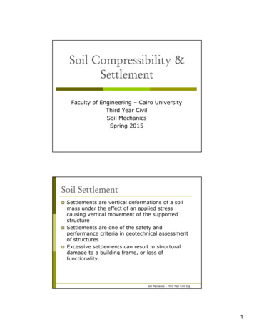
2Soil Mechanics Laboratory ManualReport PreparationIn the classroom laboratory, most experiments described herein will probably be conductedin small groups. However, the laboratory report should be written by each. studentindividually. This is one way for students to improve their technical writing skills. Eachreport should contain:1. Cover page-This page should include the title of the experiment, name, and date onwhich the experiment was performed.2. Following the cover page, the items listed below should be included in the body ofthe report:a. Purpose of the experimentb. Equipment usedc. A schematic diagram of the main equipment usedd. A brief description of the test procedure3. Results-This should include the data sheet(s), sample calculations(s), and therequired graph(s).4. Conclusion-A discussion of the accuracy of the test procedure should be includedin the conclusion, along with any possible sources of error.120r--- ---r-----'1200!:----''----'- 1;':5,--.-L-.,!25(a)Figure 1-1.(a) A poorly drawn graph fordry unit weight of soil vs.moisture content80 0!;----'--!c-5-----:;1';;-0-- 15Moisture content, w (%)(b)(b) The results'given in (a),drawn in a more presentablemanner
Soil Mechanics Laboratory Manual3Graphs and Tables Prepared for the ReportGraphs and tables should be prepared as neatly as possible. Always give the units. Graphsshould be made as large as possible, and they should be properly labeled. Examples of apoorly-drawn graph and an acceptable graph are shown in Fig. 1-1. When necessary, Frenchcurves and a straight edge should be used in preparing graphs.Table 1-1. Conversion FactorsLength.,,1 in.1ft 25.4 mm0.3048 m304.8 mm1 mm1m,.!- 1Area1 em21 in 31 ft31ft'16.387 em 30.028317 m328.3168 II em31 ftls304.8 m\ll/s0.3048 m/s5.08 mm/s0.00508 m/sI em/s1.969 ftlmin1034643.6 ftlyear1 : x 10-2 in.x 10-3 ftin.ft6.4516 x 10-4 m26.4516 em2645.16 mm2929 x 1O-4m 2929.03 em292903 mm 21 in. 2 ,l'3.9373.28139.373.281.,,--. ,:l:11 m20.155 in 21.076 x 10⁻³ 1550 in 210.76 ft2 ·. iVolume'1 iI m3. ii0.061 in.'3.531 x 10⁻⁵ ft'61023.74 in 335.315 ft3:)-,,11Velocity1 ftlmin-J,i:J,,{,i . ,;1ForeeI Ib4.448 NIN1 kN0.224821b0.22482 kipStress1 Ib/in. 2I Ib/ft26.9 kN/m 2I kN/m 247,88 N/m2O.1451b/in 22.089 x 10.2 Ib/WUnit WeightIlb/ft3157.06 N/m 31 kN/m 36.367 Ib/ft3Coefficient ofConsolidation1 in. 2/sI W/s6.452 em 2/s929.03 cm 2/sI em 2/s0.155 in?/s2.883 x 103 ft2/month1 kg2.20461b2.2046 x W-3 kipMass-
,4Soil Mechanics Laboratorv ManualUnitsIt may be necessary to express the results of laboratory tests in a given system of units. Atthis time in the United States, both the English and the SI system of units are used.Conversion of units may be necessary in preparing reports. Some selected conversion factorsfrom the English to the SI units and from SI to English units are given in Table 1-1.Standard Test ProceduresIn the United States, most laboratories conducting tests on soils for engineering purposesfollow the procedures outline by the American Society for Testing and Materials (ASTM)and the American Association of State Highway and Transportation Officials (AASHTO).The procedures and equipment for soil tests may vary slightly from laboratory to laboratory,but the basic concepts remain the same. The test procedures described in this manual maynot be exactly the same as specified by ASTM or AASHTO; however, for the .students, it isbeneficial to know the standard test designations and compare them with the laboratory workactually done. For this reason some selected AASHTO and ASTM standard test designationsare given in Table 1-2.Water contentSpecific gravitySieve analysisHydrometer alysisLiquid limitPlastic limitShrinkage limitStandard Proctor compactionModified Proctor compactionField density by sand conePermeability of granular soilConsolidationDirect shear (granular soil)Unconfined compressionTriaxialAASHTO Soil Classification SystemUnified Soil Classification SystemT-265T-IOOT-87, T-88T-87, 82D-2487I
2Determination ofWater ContentIntroductionMost laboratory tests in soil mechanics require the determination of water content. Watercontent is defined asw weight of water present in a given soil massweight of dry soil(2.1)Water content is usually expressed in percent.For better results, the minimum size of the most soil specimens should be approximatelyas given in Table 2-1. These values are consistent with ASTM Test Designation D-2216.Table 2-1. Minimum Size of Moist Soil Samples toDetermine Water Content0.4252.04.759.519.0401043/8 in.3/4 in.205010050025005
6Soil Mechanics Laboratory ManualEquipment1.2.3.Moisture can(s).Moisture cans are available in various sizes [for example, 2-in. (50,S mm) diameterand % in. (22.2 mm) high, 3.5-in. (S8.9 mm) diameter and 2 in. (50.S mm) high).Oven with temperature control.For drying, the temperature of oven is generally kept between 105 C to 110 C. Ahigher temperature should be avoided to prevent the burning of organic matter in thesoil.Balance.The balance should have a readability of 0.01 g for specimens having amass of200g or less. If the specimen has a mass of over 200 g, the readability should be 0.1 g.Procedure1.2.3.4.5.6.Determine the mass (g) of the empty moisture can plus its cap (WI)' and also record. the number.Place a sample of representative moist soil in the can. Close the can with its cap toavoid loss of moisture.Determine the combined mass (g) ofthe closed can and moist soil (Wz).Remove the cap from the top of the can and place it on the bottom (of the can).Put the can (Step 4) in the oven to dry the soil to a constant weight. In most cases,24 hours of drying is enough.Determine the combined mass (g) of the dry soil sample plus the can and its cap (W3)'Calculation1.2.3.Calculate the mass of moisture W2 - W3Calculate the mass of dry soil W3 - WICalculate the water contentW2-W3w (%) --''---'''- x 100W3 - WI(2.2)Report the water content to the nearest 1% or 0.1 % as appropriate based on the sizeof the specimen.A sample calculation of water content is given in Table 2-2.
Soil Mechanics Laboratory Manual7Table 2-2. Determination of Water ContentDescription of sOil ----"B"'-fi"'Q"'"W,u.'f7'-'S""/Z"' Vw.c!."" ,LV-----Sample No. 4'--Location -,-Tested ,, by Can No.Date423/54Mass of can, WI/73//8.92/6.07Mass of can wet soil, W2 (g)43.5252./939.43Mass of can dry soil,. W3 (g)39.8647.6/36./3Mass of moisture, W2 - W3 (g)3.664.583.30Mass of dry soil, W3 - WI (g)22.5528.6920.06/6.216.016.5Moisture content, w(%) W-W23 X 100w,- Average rnoisture content, W/6.2%General Commentsa.b.c. Most natural soils, which are sandy and gravelly in nature, may have water contentsup to about 15 to 20%. In natural fine-grained (silty or clayey) soils, water contentsup to about 50 to 80% can be found. However, peat and highly organic soils withwater contents up to about 500% are not uncommon.Typical values of water content for various types of natural soils in a saturated stateare shown in Table 2-3.Some organic soils may decompose during oven drying at 110 C. An oven dryingtemperature of n 0 may be too high for soils containing gypsum, as this materialslowly dehydrates. According to ASTM, 'a drying temperature of 60 C is moreappropriate for such soils.Cooling the dry soil after oven drying (Step 5) in a desiccator is recommended. Itprevents absorption of moisture from the atmosphere .
8Soil Mechanics Laboratory ManualTable 2-3. Typical Values of Water Contentin a,Saturated StateLoose uniforll sandDense uniform sandLoose angular-grained silty sandDense angular-grained silty sandStiff clay ,Soft claySoft organic clayGlacial till25-3012-1625152030-5080-13010
3Specific Gravity ofSoil SolidsIntroductionThe specific gravity of a given material is defined as the ratio of the weight of a givenvolume of the material to the weight of an equal volume of distilled water. In soil mechanics,the specific gravity of soil solids (which is often referred to as the specific gravity of soil) isan important parameter for calculation of the weight-volume relationship. Thus specificgravity, G" is defined asG unit weight (or density) of soil solids only,unit weight (or density) or waterorG, W, IV,pzW,(3.1)V,p"where . W, mass of soil solids (g).V, volume of soil solids (cm3)Pw density of water (glcm3 ).The general ranges of the values of G, for various soils are given in Table 3-1. . Theprocedure for determination of specific gravity, G" described here is applicable for soilscomposed ofparticles smaller than 4.75 mm (No.4 U.S. sieve) in size.9
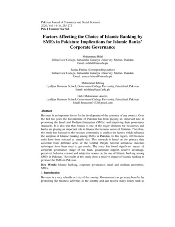
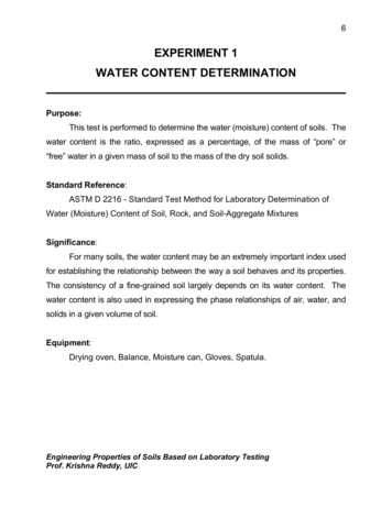
-10Soil Mechanics Laboratorv ManualTable 3-1. General Ranges of Gs for Various SoilsSandSiltsClay and silty clayOrganic soil2.63-2.672.65-2.72.67-2.9less than 2Equipment1. Volumetric flask (500 ml)2. Thermometer graduated in O.soC division scale3. Balance sensitive up to 0.01 g4. Distilled water5. Bunsen bumer and a stand (and/or vacuum pump or aspirator)6. Evaporating dishes7. Spatula8. Plastic squeeze bottle9. Drying ovenThe equipment for this experiment is shown in Fig. 3-1.Figure 3-1. Equipment for conducting specific gravity test.!
Soil Mechanics Laboratory 15.16.Clean the volumetric flask well and dry it.Carefully fill the flask with de-aired, distilled water up to the 500 ml mark (bottomof the meniscus should be at the 500 ml mark).Determine the mass of the flask and the water filled to the 500 ml mark (Wi)'Insert the thermometer into the flask with the water and determine the temperatureof the water T Ti DC.Put approximately 100 grams of air dry soil into an evaporating dish.If the soil is cohesive, add water (de-aired and distilled) to the soil and mix it to theform of a smooth paste. Keep it soaked for about one-half to one hour in theevaporating dish. (Note: This step is not necessary for granular, i.e., noncohesive,soils.)Transfer the soil (if granular) or the soil paste (if cohesive) into the volumetric flask.Add distilled water to the volumetric flask containing the soil (or the soil paste) tomake it about two-thirds full.Remove the air from the soil-water mixture. This can be done by:a. Gently boiling the flask containing the soil-water mixture for about 15 to 20minutes. Accompany the boiling with continuous agitation of the flask. (Iftoo much heat is applied, the soil may boil over.) Orb. Apply vacuum by a vacuum pump or aspirator until all of the entrapped airis out.This is an extremely important step. Most ofthe errors in the results of this testare due to entrapped air which is not removed.Bring the temperature of the soil-water mixture in the volumetric flask down to roomtemperature, i.e., Ti DC-see Step 4. (This temperature of the water is at room temperature.)Add de-aired, distilled water to the volumetric flask until the bottom of the meniscustouches the 500 m1 mark. Also dry the outside of the flask and the inside of the neckabove. the meniscus. Determine the combined mass of the bottle plus soil plus water (W2).Just as a precaution, check the temperature of the soil and water in the flask to see ifitis Ti D. 1DC or not.Pour the soil and water into an evaporating dish. Use a plastic squeeze bottle andwash the inside of the flask. Make sure that no soil is left inside.Put the evaporating dish in a oven to dry to a constant weight.Determine the mass of the dry soil in the evaporating dish (W,).Calculation1.Calculate the specific gravityG Smass of soil, W,mass of equal volume of soil
12whereSoil Mechanics Laboratory Manualmass of soil Wsmass of equal volume of water, Ww (WI Ws)-W2So(3.2)Specific gravity is generally reported on the value of the density of water at 20 C. SoG;(at20 c) Gs(atljoq [ Pw "r,Oq]Pw(at20 C)(3.3) G, " Tl"q A(3.4)Pw density of water.The values of A are given in Table 3-2.Table 3-2. Values of A [Eq. 860.99830.99800.99770.9974At least three specific gravity tests should be conducted. Fot correct results, these valuesshould not vary by more than 2 to 3%. A sample calculation for specific gravity is shownin Table 3-3.
Soil Mechanics Laboratory Manual13Table 3-3. Specific Gravity of Soil SolidsDescription of soilLight brown sandy SiltVolume of fiask at 20"C 500 mlTemperature of testSample No.23 "C23A0.9993(Table 3-2)Location .,--Tested by689Mass of flask water filled to mark, WJ (g)666.0674.0652.0Mass of flask soil water filled to mark,W2 (g)722.0738.3709.93Mass of dry soil, Ws (g)99.0103.092.0Mass of equal volume of water as the soilsolids, Ww (g) (WI Ws ) - W237038.734.072.682.662.702.682.662.70Volumetric flask No.· I·. · ·· . Datem.·.I*(2.68 2.66 2.70) 2.683Average Gs -c-
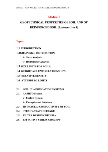
4Sieve AnalysisIntroductionIn order to classifY a: soil for engineering purposes, one needs to know the distribution of thesize of grains in a given soil mass. Sieve analysis is a method used to deter mine the grainsize distribution of soils. Sieves are made of woven wires with square openings. Note that.as the sieve number increases the size of the openings decreases. Table 4-1 gives a list of theU.S. standard sieve numbers with their corresponding size of openings. For all practicalpurposes, the No. 200 sieve is the sieve with the smallest opening that should be used for thetest. The sieves that are most commonly used for soil tests have a diameter of 8 in. (203 mm).A stack of sieves is shown in Fig. 4.-1.The method of sieve analysis described here is applicable for soils that are mostlygranular with some or no fines. Sieve analysis does not provide information as to shape ofparticles.Table 4-1. U.S. Sieve 4020027040015 O.o?50.0530.038
16Soil Mechanics Laboratory ManualFigure 4-1. A stack of sieves with a pan at thebottom and a cover on the top.Equipment1.2.3.4.5.Sieves, a bottom pan, and a coverNote: Sieve numbers 4, 10, 20, 40, 60, 140, and 200 are generally used for moststandard sieve analysis work.A balance sensitive up to 0.1 gMortar and rubber tipped pestleOvenMechanical sieve shakerProcedure1.2.3.Collect a representative oven dry soil sample. Samples having largest particles of thesize of No . 4 sieve openings (4.75 rnm) should be about 500 grams. For soils havinglargest particles of size greater than 4.75 rnm, larger weights are needed.Break the soil sample into individual particles using a mortar and a rubber-tippedpestle. (Note: The idea is to break up the soil into individual particles, not to breakthe particles themselves.)Determine the mass ofthe sample accurately to 0.1 g CW).
Soil Mechanics Laboratory Manual17Figure 4-2. Washing of the soil retained on No. 200 sieve.4.Prepare a stack of sieves. A sieve with larger openings is placed above a sieve withsmaller openings. The sieve at the bottom should be No. 200. A bottom pan shouldbe placed under sieve No. 200. As mentioned before, the sieves that are generallyused in a stack are Nos. 4, 10,20,40,60, 140, and 200; however, more sieves can beplaced in between.5. Pour the soil prepared in Step 2 into the stack of sieves from the top.6. Place the cover on the top of the stack of sieves.7. Run the stack of sieves through a sieve shaker for about 10 to 15 minutes.8. Stop the sieve shaker and remove the stack of sieves.9. Weigh the amount of soil retained on each sieve and the bottom pan.10. If a considerable amount of soil with silty and clayey fractions is retained on the No.200 sieve, it has to be washed. Washing is done by taking the No. 200 sieve with thesoilretained on it and pouring water through the sieve from a tap in the laboratory(Fig. 4-'-2).When the water passing through the sieve is clean, stop the flow of water. Transfer the soilretained on the sieve at the end of washing to a porcelain evaporating dish by back washing(Fig. 4-'-3). Put it in the oven to dry to a constant weight. (Note: This step is not necessaryif the amount of soil retained on the No. 200 sieve is small.)Determine the mass of the dry soil retained on.No. 200 sieve. The difference betweenthis mass and that retained on No. 200 sieve determined in Step 9 is the mass of soil that haswashed through.
18Soil Mechanics Laboratory Manuali-- Figure 4-3. Back washing to transfer the soil retained onNo. 200 sieve to an evaporating dish.Calculation1.Calculate the percent of soil retained on the nth sieve (counting from the top) 2.w,.mass retained,x 100 Rntotal mass, W (Step 3)(4.1)Calculate the cumulative percent of soil retained on the nth sievej"",n(4.2) LRn; 13.Calculate the cumulative percent passing through the nth sievei n percent fmer 100 -L Rn(4.3)1 1Note: If soil retained on No.200 sieve is washed, the dry unit weight determined afterwashing (Step 10) should be used to calculate percent finer (than No. 200 sieve). The weightlost due to washing should be added to the weight of the soil retained on the pan.
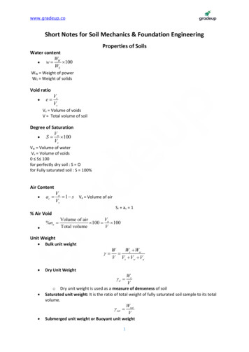
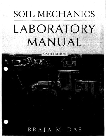
Soil Mechanics Laboratory ManualI19A sample calculation of sieve analysis is shown in Table 4-2. i.UTable 4-2. Sieve AnalysisDescription of soil e",,5,--Sample No. 2,,----Mass of oven dry specimen, W····1·.·.·/'500gLocationTested byDate, /6.924.975.1300.60050.210.034.965. 498.3Mass loss during sieve analysisGraphs W, w- w,wx 100 0.34% (OK.if less than 2%)tJ. 13;The grain-size distribution obtained from the sieve analysis is plotted in a semi-logarithmicgraph paper with grain size plotted on the log scale and percent finer plotted on the naturalscale. Figure is a grain-size distribution plot for the calculation shown in Table 4--2.
20Soil Mechanics Laboratory Manual100r---"".""80lJ 60'""gI'""1\ 40\1\200101-\J .Grain size, D (mm)0.1.,-,Figure 4-4. Plot of percent finer vs. grain size from thecalculation shown in Table 4-2.The grain-size distribution plot helps to estimate the percent finer than a given sieve sizewhich might not have been used during the test. .Other CalculationsI.2.Determine D IO , D 30 , and D60 (from Fig. 4-4), which are, respectively, the diameterscorresponding to percents finer of 10%, 30%, and 60%.Calculate the uniformity coefficient (Cu ) and the coefficient of gradation (Cc ) usingthe following equations:C D60U11D10(4.4)7 - .\D.\;J,As an example, from Fig. 4-4,(4.5)D60 0.46 mm,D30 Soc u0.460.098 4.690.21 mm, and L10 0.098 mm.
, -Soil Mechanics Laboratory Manual21and C,(0.21)2(0.46)(0.098) 0.98General CommentsThe diameter, DID' is generally referred to as effective size. The effective size is used forseveral empirical correlations, such as coefficient of permeability. The coefficient ofgradation, Cu , is a parameter which indicates the range of distribution of grain sizes in agiven soil specimen. If Cu is relatively large, it indicates a well graded soil. If Cu is nearlyequal to one, it means that the soil grains are of approximately equal size, and the soil maybe referred to as a poorly graded soil.Figure 4-5 shows the general nature of the grain-size distribution curves for a wellgraded and a poorly graded soil. In some instances, a soil may have a combination of two ormore uniformly graded fractions, and this soil is referred to as gap graded. The grain-sizedistribution curve for a gap graded soil is also shown in Fig. 4-5.The parameter Cc is also referred to as the coefficient of curvature. For sand, if ;; isgreater than 6 and Cc is between I and 3, it is considered well graded. However, for a gravelto be well-graded, Cu should be greater than 4 and Cc must be between I and 3.The DIS and Dss sizes are used for design of filters. The DSD size is used for correlationof the liquefaction potential of saturated granular soil during earthquakes.
22Soil Mechanics LaboratoryManualWell gradedPoorly gradedGap gradedGrain size (log scale)Figure 4-5. General nature of grain-size distributionof well graded, poorly graded and gap.graded soil.
i'5'Hydrometer AnalysisIntroduction-Hydrometer analysis is the procedure generally adopted for determination of the particle-sizedistribution in a soil for the fraction that is finer than No. 200 sieve size (0.075 mm). Thelower limit of the particle-size determined by this procedure is about 0.001 mm.In hydrometer analysis, a soil specimen is dispersed in water. In a dispersed state in thewater, the soil particles will settle individually. It is assumed that the soil particles arespheres, and the velocity ofthe particles can be given by Stoke's law as'U Ys-Y" D2(5.1)181)whereu velocity (cm/s)y s specific weight of soil solids (g/cm3 )y w unit weight of water (g/cm 3) ,11 viscosity of water(: )D diameter of the soil particleIf a hydrometer is suspended in water in which soil is dispersed (Fig. 5-1), it willmeasure the specific gravity of the soil-water suspension at a depth L. The depth L is calledthe effective depth. So, at a time t minutes from the beginning of the test, the soil particles'that settle beyond the zone of measurement (i.e., beyond the effective .depth L) will have adiameter given by,L (cm)(Ys-Yw) g/cm 3t (min) x 60181)(: )23
24Soil Mechanics Laboratory ManualHydrometeroMeniscuscorrection 601-1rL1Figure 5-1. Hydrometer suspended in water inwhich the soil is dispersed.L(cm)t (min)1800'1'\(S.2)30'1'\where A 1 - - - - " - - 60(Y8 -Yw)(S.3)In the test procednre described here, the ASTM 152-H type of hydrometer will be used.From Fig. S-1 it can be seen that, based on the hydrometer reading (which increases fromzero to 60 in the ASTM 152-H type of hydrometer), the value of L will change. The mag.nitude of L can be given asL LI1(L -AVB)- -22c(S.4)
Soil Mechanics Laboratory Manual25where LI distance between the top of hydrometer bulb to the mark for a hydrometerreading. For a hydrometer reading of zero, LI 10.5 cm. Also, for a Hydrometer reading of 50 glliter, LI 2.3 cm. Thus, in general, for a given hydrometer readingLI (cm) 10.5 - (0.55 2.3) x (hydrometer reading)1L2 14cmVB volume of the hydrometer bulb 67.0 cm3Ac cross-sectional area of the hydrometer cylinder 27.8 cm2Based on Eq. (5.4), the variation of L with hydrometer reading is shown in Table 5-1.For actual calculation purposes we al o need to know the values of A given by Equation(5.3). An example of this calculation is shown below.where Gs specific gravity of soil solidsThusA 3011(5.5)(Gs -l)y"For example, if the temperature of the water is 25 b C,11 0.0911 X 10⁻⁴(; )and Gs 2.7A 30(0.0911 X 10⁻⁴) ' 0.0127 .(2.7 -1)(1)The variations of A with Gs and the water temperature are shown in Table 5-2.
26Soil Mechanics Laboratory ManualTable 5-1. Variation of Lwith hydrometer readingASTM 152-H 9The ASTM 152-H type of hydrometer is c:alibrated up to a reading of 60 at a tem- peratureof20oe for soil particles having a Gs 2.65. A hydrometer reading of, say, 30 at a given timeof a test means thatthere are 30 g of soil solids (Gs 2.65) in. suspension per 1000 cc of soilwater mixture at a temperature of20oe at a depth where the specific gravity of the soil-watersuspension is measured (i.e., L). From this measurement, we can determine the percentageof soil still in suspension at time t from the beginning of the test and all the soil particles willhave diameters smaller than D calculated by Equation (5.2). However, in the actualexperimental work, some corrections to the observed hydrometer readings need to be applied.They are as follows:
Soil Mechanics Laboratory Manual27Table 5-2. Variation of A with emperature correction (FT)-The actual temperature of the test may not be 20 C.The temperature correction (F T) may be approximated asF T -4.85 0.25T(for Tbetween 15 C and 28 C)2.3.(5.6)where F T temperature correction to the observed reading(can be either positive or negative)T temp
Most laboratory tests in soil mechanics require the determination of water content. Water content is defined as weight of water present in a given soil mass w weight of dry soil (2.1) Water content is usually expressed in percent. For better results, the minimum size of the most soil specimens should be approximately as given in Table 2-1.