Transcription
PDHonline Course M409 (3 PDH) HVACPsychrometric Analysis to AvoidMoisture ProblemsInstructor: Fred W. Dougherty, P.E., B.A.E., M.M.E.2011PDH Online PDH Center5272 Meadow Estates DriveFairfax, VA 22030-6658Phone & Fax: 703-988-0088www.PDHonline.orgwww.PDHcenter.comAn Approved Continuing Education Provider
www.PDHcenter.comPDHonline Course M409www.PDHonline.orgHVAC Psychrometric Analysis to AvoidMoisture ProblemsFred W. Dougherty, P.E., B.A.E., M.M.E.COURSE CONTENT1.ScopeThis course reviews the application of psychrometrics to the analysis andselection of HVAC cooling systems. At this stage of the design process, heatingand cooling loads will have been computed for the project, and an initial selectionof heating and cooling apparatus will have been made. Thus, the building roomloads and cooling coil capacities are known. Psychrometric analysis is applied tothe cooling system because the cooling system is the source of moisture problemsand “sick buildingsyndrome”. Afterpsychrometricanalysis, it may benecessary to repeatthe selection processto avoid moistureproblems revealed.2.The DesignIterationPsychrometricanalysis is only onestep in the process ofDX cooling systemdesign and equipmentselection. Thisprocess is shown as aflow chart in figure 1.Steps 1 through 5follow the process offinding a 2011 Fred W. DoughertyPage 2 of 30
www.PDHcenter.comPDHonline Course M409www.PDHonline.orgmanufacturer, model, and size to match the total and sensible capacity with thecalculated loads. Once a match is found, step 6, psychrometric analysis isrequired to ensure that the selected equipment can supply conditioned air that willfollow the room load process line. How this is done is explained in this course.3.DefinitionsThe following terms will be used throughout this course.A building is a roofed and walled structure with controlled environment, built forhuman occupation and use.A ceiling plenum is a cavity within the pressure envelope that is above a roomand that is formed by a dropped lay-in ceiling and floor or roof structure above.Room walls do not necessarily extend above the dropped ceiling to the structureabove.The pressure envelope is the primary air barrier of the building, which is sealedto provide the greatest resistance to air leakage from the unconditionedenvironment. One or more zones may be within a building pressure envelope.Return air is the portion of the supply air that is recirculated to thecooling/heating apparatus after being collected by the return grilles in the zone.A return air plenum is a ceiling plenum with an unobstructed path to an airhandler return, and that contains no flammable materials or surfaces.A room is the part of a space bounded by walls and a ceiling that is usuallyroutinely occupied and served by grilles and registers to supply and recirculate orexhaust conditioned air. The term room may denote zone on the psych chart.A space is a single room, with or without a ceiling plenum.Supply air is the all of the air delivered by the cooling/heating apparatus to thesupply air diffusers in the zone.The supply air critical state is the maximum temperature and dew point of thesupply air that will satisfy the zone design temperature and relative humidity atdesign air flow and cooling load. 2011 Fred W. DoughertyPage 3 of 30
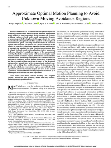
www.PDHcenter.comPDHonline Course M409www.PDHonline.orgVentilation air, also called outdoor air, is air from outdoors that may be mixedwith return air before passing into the cooling/heating apparatus, may beintroduced to the apparatus directly before entering a zone, or in certain rarecircumstances, may be introduced un-tempered into a zone.A zone is a group of spaces or rooms within the thermal and pressure envelopeswhich are served by a single air handling system.4.The Psychrometric ChartThis course is about applying psychrometrics to actual air conditioning projects.It is assumed that the student is already familiar with psychrometric processes.The following brief refresher will hopefully help brush away any cobwebs.The psychrometric chart maps two primary and six secondary properties of air.The primary properties are dry bulb temperature and water vapor concentration.All of the properties are expressed as concentrations in dry air. Thepsychrometric chart shown below has two principle axes – the horizontal axis isdry bulb temperature, tdb, in C or F, and the vertical axis is water vaporcontent, usually labeled as humidity ratio, W, expressed in IP units as pounds ofmoisture per pound of dry air (lbs H2O/lb) or grains of moisture per pound of dryair (gr/lb). There are 7000 grains to one pound.On the saturation line, all of thewater vapor in the air hascondensed to liquid. There is nostable state to the left of thesaturation line.The six secondary properties are:wet bulb temperature twb – The lowest temperature that can be reached bythe evaporation of water only.relative humidity, rh – the amount of water vapor in air at a giventemperature as a percentage of the total amount of water vapor in saturatedair at the same dry bulb temperature. Also, the vapor pressure of the air 2011 Fred W. DoughertyPage 4 of 30
www.PDHcenter.comPDHonline Course M409www.PDHonline.orgwater vapor mixture as a percentage of the vapor pressure of saturated airat the same dry bulb temperature.dew point temperature, tdp – the temperature to which an air-water vapormixture must be cooled for the water vapor to condense into liquid water.enthalpy, h – the specific energy of the moist air, expressed in IP units asBtu/lb of dry air.specific volume, v – the total volume of dry air and water vapor in units ofcubic feet per pound of dry air (ft3/lb). This is the reciprocal of the densityof the air/water vapor mixture, lb/ft3.water vapor pressure, Vp - the pressure exerted by the molecules of watervapor in a saturated mixture of water vapor and dry air at a giventemperature and at standard pressure for the altitude of the chart.The Psychrometric Chart, IP UnitsNote that these are “secondary” because they are all fully defined by dry bulbtemperature and humidity ratio alone. However if any two of the nine propertiesare known, all of the others can be found by reading from the chart or performing 2011 Fred W. DoughertyPage 5 of 30
www.PDHcenter.comPDHonline Course M409www.PDHonline.orga calculation. Also, dew point and vapor pressure are both defined by horizontallines that intersect the vertical axis, so that for any humidity ratio (vertical axis),there is a unique value of tdp and Vp.The curved line bounding the left of the chart is the saturation line. On thesaturation line, the dry bulb temperature is the dew point and wet bulbtemperature, and relative humidity is 100%. Thus, on the saturation line:tdb tdp tdb twb and rh 100%Any point on the psychrometric chart is a state point because it defines thethermodynamic state – the temperature and humidity ratio - of the air at thatpoint. If the air at a given state is acted upon by an external process such asheating, mechanical cooling, or humidification it will be changed to another state.The path between the initial and final states is a process line.If any two properties of air are known, then all of the others can be found byreading from the chart or making a computation. For example, if outdoor airtemperature and relative humidity are known, say 90 F and 70% rh, that pointcan be plotted on the chart above, thus fully defining all of the properties of theoutdoor air at that point, including wet bulb temperature, dew point, enthalpy, andspecific volume.Air conditioning cooling load is defined in terms of sensible heat load and totalheat load. Likewise, a mechanical cooling coil, DX or chilled water, is definedin terms of sensible heat capacity and total heat capacity. A change in thesensible heat of a mass of air creates a measurable change in its dry bulbtemperature, tdb. A change in the latent heat creates a measurable change in thehumidity ratio, W. Total heat is the sum of the latent heat and sensible heat of amass of air. A change in the total heat of a mass of air is equivalent to a changein its enthalpy, h. These changes are quantified by the following formulas: Qs tdb * Cc * rho * cp * min/hr Ql W * Cc * rho * QLV * min/hr Qt h * Cc * rho * min/hr Qs Qlwhere (IP units) Qs is the change in sensible heat of the flowing air (Btu/hr) Ql is the change in latent heat of the flowing air (Btu/hr) Qt is the change in total heat of the flowing air (Btu/hr)Cc is the air flow rate (ft3/min) 2011 Fred W. DoughertyPage 6 of 30
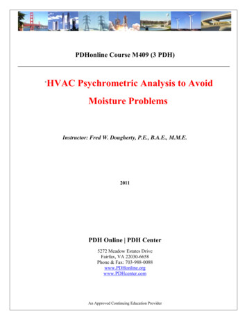
www.PDHcenter.comPDHonline Course M409www.PDHonline.orgrho is the average air density of the flowing air (lb/ft3)cp is the specific heat of air (Btu/lb/ F)QLV is the latent heat of vaporization of water (Btu/lb H2O)for air at standard conditions:rho .075, cp .24, QLV 1076 Qs tdb * Cc * 1.08 Ql W * Cc * 4840 Qt h * Cc * 4.5(1)(2)(3)In this course, loads and capacity will be expressed in terms of sensible heat andtotal heat, because that is how most air conditioner system published performancedata is expressed.Paper psychrometric charts suitable for plotting are often available from HVACmanufacturer’s representatives. 50 sheet pads of charts similar to the ones usedfor this course are available from the ASHRAE bookstore. Also, there arenumerous software programs for plotting psychrometric analysis which may befound on the web. This course was developed using the ASHRAE PsychrometricAnalysis Program, available from ASHRAE on CD. A blank chart is included atthe end of the course that can be printed out for plotting exercises.5.Cooling System Psychrometric State PointsIn this course, psychrometric state points will be identified as follows:1 – room air1A – supply air critical state point – not a physical point2 – outdoor air3A – mixed air entering heat pipe or pre-cool coil, where applicable3 – mixed air entering cooling coil4 – air leaving cooling coil4A – air leaving heat pipe or reheat coil, where applicableFigure 2 – DX Cooling System Schematic 2011 Fred W. DoughertyPage 7 of 30
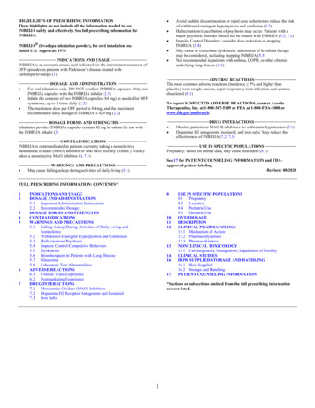
www.PDHcenter.comPDHonline Course M409www.PDHonline.orgFigure 2 is a schematic representation of a cooling system, showing the locationsof the state points except for point 1A, which is a calculated, not a physical, point.Figure 3 is a typical psychrometric chart with important parameters labeled. Thecooling design point shown is for a five ton rooftop unit serving a small officezone. (The term “room” can be taken to mean all of the rooms in the zone.)Room air at 76 and 57% relative humidity is mixed with outdoor air at 94 drybulb and 78 wet bulb. The mixed air passes over a cooling coil, where it iscooled to 59.6 at 91% rh and then delivered to the room (zone) to carry awaycooling load heat and moisture.The most important elements of the psychrometric cycle, from the standpoint ofthe engineer, are room and coil sensible heat ratio, room dew point, and apparatusdew point. Plotting these on a psych chart, will quickly tell you whether a simplesystem will do the job, or whether additional components and capabilities will beneeded.Process LinesThe lines on a psychrometric chart we will call “process” lines. Referring tofigure 3, line 1-1A is the “room process line”. Point 1A is the supply air criticalFREOFPERTEMATION-BSATURPY.016COIL60SUPPLY AIR CRITICAL STATE 1A65%901 ROOM AIR700.0021009085807570656055504540.004IRYVE HUMIDIT10% RELATI512.35.006ARY13.ODB/OWB 95.0/78.0,RDB/RWB76.0/65.04540%SUPPLYAIR 2050 CFM, OA 250 CFM4030%35 EDB/EWB 78.2/66.7 LDB/LWB 59.5/57.9REDB/REWB 59.9/58.420%10.008DLB.ERT. P%5050513.454035.010.FCUEUMOL%ROOM42,400 Btuh55%COOLING LOADS: TOTAL60SENSIBLE 36,300 Btuh5015.0123 MIXED AIR8060 ROOM455COIL LEAVING%20.014706595THAL75700V14.EN2 OUTDOOR AIRATUDUNPOTUPER30.018514.Office System Psychrometric Chart2575- DR35HUMIDITY RATIO, LBS MOISTURE PER LB DRY AIRYAIR80.00015 BULB TEMPERATURE DEGREES2FAHRENHEIT0DRYENTHALPFIGURE 35 TON PACKAGED AC, SENSIBLE COOLING CAPACITY 41,960 Btuh, TOTAL COOLING CAPACITY 57,430 BtuhCOIL COOLING LOADS: SENSIBLE 41,300 Btuh, TOTAL 55,600 Btuh 2011 Fred W. DoughertyPage 8 of 30
www.PDHcenter.comPDHonline Course M409www.PDHonline.orgstate point and represents the maximum state of the supply air that will satisfythe room load. As the supply air cools and dehumidifies the room, it will followthe slope of the room process line. Thus, the air leaving the cooling apparatusmust be at the same or lower temperature and dew point than point 1A or thedesired room temperature and relative humidity cannot be maintained at designconditions. Line 3-4 is the coil process line. Supply air at the flow rate (cfm) ofthe cooling apparatus enters the coil at state point 3 and leaves the coil at statepoint 4, where it is introduced into the room, picks up the sensible and latent load,and then is returned to the cooling apparatus for reprocessing.For a cooling system to be able to satisfy the design conditions of the room andoutdoor air loads, the coil process line must satisfy two conditions. First, the coilleaving air temperature, point 4 or 4A, must be low enough to significantlydehumidify the air, generally under 60 F. Second, the coil process line mustcross the room process line so that the supply air dew point and dry bulbtemperature is less than point 1A. That is, point 4 must be cooler and drier thanpoint 1A, as shown on Figures 3 and 4. These conditions may be difficult to meetwith ordinary DX cooling systems. If either condition is not met, then additionalprocesses may be necessary, such as outdoor air pre-treatment, mixed air precooling, or coil leaving air reheat. These processes must be tailored to cause thesupply air, point 4 or 4A, to end up on or below and cooler than point 1A.Plotting Points on the Psychrometric ChartTo do psychrometric analysis, it is necessary to use known data to calculate theunknown points. Referring to Figure 3, the known data are as follows:odb tdb2
The psychrometric chart maps two primary and six secondary properties of air. The primary properties are dry bulb temperature and water vapor concentration. All of the properties are expressed as concentrations in dry air. The psychrometric chart shown below has two principle axes –