Transcription
Expanded “Cookbook” Instructions for the TeradyneIntegra J750 Test SystemFinal ReportTeamMay 07-12ClientECpE DepartmentFaculty AdvisorDr. WeberTeam MembersMurwan Abdelbasir, EEBrent Hewitt-Borde, EEJonathan Brown, EEPaul Jennings, EERobert Stolpman, EEREPORT DISCLAIMER NOTICEDISCLAIMER: This document was developed as a part of the requirements of anelectrical and computer engineering course at Iowa State University, Ames, Iowa.This document does not constitute a professional engineering design or a professionalland surveying document. Although the information is intended to be accurate, theassociated students, faculty, and Iowa State University make no claims, promises, orguarantees about the accuracy, completeness, quality, or adequacy of the information.The user of this document shall ensure that any such use does not violate any laws withregard to professional licensing and certification requirements. This use includes anywork resulting from this student prepared document that is required to be under theresponsible charge of a licensed engineer or surveyor. This document is copyrighted bythe students who produced this document and the associated faculty advisors. No partmay be reproduced without the written permission of the senior design coursecoordinator.Date Submitted05/02/2007
Contents1 Introductory material1.1 Executive summary . . . . . . . . . . . . . .1.1.1 Project requirements . . . . . . . . .1.1.2 Actual project activities . . . . . . .1.1.3 Final results . . . . . . . . . . . . . .1.1.4 Recommendations for follow-on work1.2 Acknowledgement . . . . . . . . . . . . . . .1.3 Problem statement and solution . . . . . . .1.3.1 Problem statement . . . . . . . . . .1.3.2 Problem solution . . . . . . . . . . .1.4 Operational environment . . . . . . . . . . .1.5 Intended user and intended use . . . . . . .1.5.1 Intended user . . . . . . . . . . . . .1.5.2 Intended use . . . . . . . . . . . . . .1.6 Assumptions and limitations . . . . . . . . .1.6.1 Assumptions . . . . . . . . . . . . . .1.6.2 Limitations . . . . . . . . . . . . . .1.7 Expected end-product and other deliverables.2 Approach and product design results2.1 Approach used . . . . . . . . . . . . . . . . . . . . .2.1.1 Functional requirements . . . . . . . . . . . .2.1.2 Design constraints . . . . . . . . . . . . . . .2.1.3 Technical approach considerations and results2.1.4 Testing approach considerations . . . . . . . .2.2 Detailed design . . . . . . . . . . . . . . . . . . . . .2.2.1 Overview of the project design . . . . . . . . .2.2.2 IG-XL and Teradyne J750 functionality . . . .2.2.3 Device selection . . . . . . . . . . . . . . . . .2.3 Implementation process . . . . . . . . . . . . . . . . .2.3.1 Channel mapping and device mating . . . . .2.3.2 Template creation . . . . . . . . . . . . . . . .2.3.3 Cookbook maintenance and improvements . .2.4 End-product testing . . . . . . . . . . . . . . . . . .2.5 Project end results . . . . . . . . . . . . . . . . . . 2326
3 Resources and schedule3.1 Personal effort requirements3.2 Other resource requirements3.3 Financial requirements . . .3.4 Project schedule . . . . . . .4 Closure materials4.1 Project evaluation . . . . . . . . . . . . . . . . .4.1.1 Project milestones for evaluation . . . .4.1.2 Evaluation criteria . . . . . . . . . . . .4.1.3 Project evaluation . . . . . . . . . . . .4.2 Commercialization . . . . . . . . . . . . . . . .4.2.1 Commercialization cost . . . . . . . . . .4.2.2 Potential market . . . . . . . . . . . . .4.3 Additional work . . . . . . . . . . . . . . . . . .4.3.1 Ongoing Teradyne project . . . . . . . .4.3.2 Additional sections for cookbook . . . .4.4 Lessons learned . . . . . . . . . . . . . . . . . .4.4.1 What went well . . . . . . . . . . . . . .4.4.2 What did not go well . . . . . . . . . . .4.4.3 Technical knowledge gained . . . . . . .4.5 Non-technical knowledge gained . . . . . . . . .4.6 Risk management . . . . . . . . . . . . . . . . .4.6.1 Predicted risks . . . . . . . . . . . . . .4.6.2 Identified risks encountered . . . . . . .4.6.3 Unidentified risks encountered . . . . . .4.6.4 Changes in risk management as a resultpated risks . . . . . . . . . . . . . . . . .4.7 Project team information . . . . . . . . . . . . .4.7.1 Client information . . . . . . . . . . . .4.7.2 Faculty advisor information . . . . . . .4.7.3 Team members' information . . . . . . .4.8 Closing summary . . . . . . . . . . . . . . . . .4.9 References . . . . . . . . . . . . . . . . . . . . . . . . . . . . . . . . . . . . . . . . . . . . . . . . . . . . . . . . . . . . . . . . . . . . . . . . . . . . . . . . . . . . . . . . . . . . . . . . . . . . . . . . . . . . . . . . . . . . . . . . . . . . . . . . . . . . . . .of unantici. . . . . . . . . . . . . . . . . . . . . . . . . . . . . . . . . . . . . . . . . . 46.47474747484849A Data sheet for AD82350B Data sheet for OP3750ii
C Data sheet for AD789250D Data sheet for AD747050E Data sheet for AD5440/AD544750iii
List of Figures12345678910111213Teradyne J750 tester . . . . . . . . .ESD wristband . . . . . . . . . . . .Lock/Unlock switch on J750 tester .ZIF DIP Socket . . . . . . . . . . . .TSSOP to DIP socket converter . . .Test procedures dialog . . . . . . . .Test procedure flow chart dialog . . .Teradyne pinout chart . . . . . . . .Final TSSOP to ZIF converter . . . .Problem definition Gannt chart . . .Technology selection Gannt chart . .Project reporting Gannt chart . . . .End project deliverables Gannt chartiv.16612131718242531323334
List of Tables12345678910Total personal efforts . . . . . . . . . . .Estimated additional resources . . . . . .Revised estimated additional resources .Final revised project costs . . . . . . . .Milestones and grading weights . . . . .Estimated design evaluation functionalityMilestone completion scoring rationale .Project evaluation . . . . . . . . . . . . .Commercialization Cost . . . . . . . . .Contact information . . . . . . . . . . .v. . . . . . . . . . . . . . . .chart. . . . . . . . . . . . .28292930354040414248
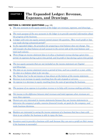
List of DefinitionsADC - Analog-to-digital converterASIO - Analog signal I/O boardCSG - Computer Support GroupDAC - Digital-to-analog converterDIB - Device interface boardDSIO - Digital signal I/O boardDSP - Digital signal processingDUT - Device under testECpE - Electrical and computer engineeringESD - Electrostatic dischargeGND GroundI/O - Input and outputIG-XL - A windows based software that utilizes Microsoft Excel and VisualBasic to develop programs for the Teradyne J750IMD - Inter-modulation distortionISU - Iowa State UniversityKbps Kilo-bits per second or 1000 bits per second.Mbps Mega-bits per second or 1000000 bits per second.MSPS Mega-samples per secondMHz Mega-HertzMSO - Mixed-signal option testing that uses analog and digital simultaneouslyPSI - Pounds per square inch, a unit of measurement for pressure exertedon a known surface areaPLCC Plastic leadless chip carrierSNR - Signal to noise ratioTDR - Time domain reflectometryTSSOP Thin shrink small outline packageTeradyne J750 - A tester donated to ISU that is used for testing printedcircuit boards and integrated circuits as shown in the figure below.ZIF Zero insertion forcevi
Figure 1: Teradyne J750 tester1Introductory materialThis section introduces the project, abstract, acknowledgements, problemstatement and solution, operating environment, intended users and uses, limitations and assumptions, expected end product and other deliverables.1.1Executive summaryThis section gives a general overview of the project requirements, plans, andactivities.1.1.1Project requirementsThe scope of this project is to expand upon previous Teradyne J750 cookbooks of instructions, which are in a manual format for the ISU Departmentof Electrical and Computer Engineering. At present the current cookbook instruction set is missing a mixed-signal option section and the present projectteam members fills this gap by reviewing, citing previous cookbooks to meetthe mixed-signal testing requirements requested by the ECpE departmentto create an extended cookbook. The team will setup and test a ten bit1
ADC, a twelve bit ADC, a ten bit DAC, a twelve bit DAC, and a 10 MHzor faster op-amp using the Teradyne J750 and document each scenario forsupport. The test scenarios and documentation have been used to create thismixed-signal cookbook.1.1.2Actual project activitiesThe project activities are outlined as follows for both semesters below.Fall 2006: Problem Definition (completed) MSO labs with vocoder chip (completed) IG-XL software code development (not completed) Technology Selection (completed) Project Reporting (completed) Weekly Email Repots, Website Updates (completed) Project Plan Development, Design Report Development (completed)Spring 2007: IG-XL code development for DAC (at present, de-bugging code) IG-XL code development for ADC (in-progress) IG-XL code development for 100 MHz Op-amp (in-progress) Poster (competed) Pin and channel maps for ADC's and DAC's (completed) Pin and channel map for 100 MHz op-amp (in-progress) DAC, ADC testing (in- progress) Overall project documentation (in-progress)2
1.1.3Final resultsThe final results are the fulfillment of the requirements in terms of documentation that has been turned in to the senior design co-coordinator. The pinand channel mapping for the ADC's and DAC's has also been completedand documented. The DIB socket converter interface has be made for theADC and DAC. At present the DAC is mounted and undergoing test debugging. The project at present is stalled due to IG-XL licensing error that haslocked the software disabling any other code development. The issue beforethe present IG-XL issue was a bad circuit breaker from since last semesterwhich caused the computer motherboard to be replaced. At present a newair-conditioner was installed enabling testing at the required temperature toresume, once the computer is fully operational.1.1.4Recommendations for follow-on workAfter consultation during our team meetings with Dr. Weber, Dr. Smith,and members of the Cyclone team at Teradyne, it was proposed to turn theTeradyne cookbook project into an ongoing project. This would take theform of a phase with outlined tasks with additional support in the form oftraining sessions for using the tester and IG-XL code development, to possiblyhave one or two students certified to do software and hardware upgrades tothe tester as well as the IG-XL software package.One important recommendation the team would strongly want to seeimplemented is for the J750 tester and its supporting equipment to be movedto a reliable room of Dr. Weber's choice so as to prevent any damage due tothe ongoing construction and upgrade to the ECpE building which will enteranother phase very soon. At present, the construction has caused powerinterruptions, computer hardware failure and disruption to the operationalenvironment within the Teradyne lab.1.2AcknowledgementThe team members extend great appreciation and would like to this opportunity to thank Dr. Robert Weber for the advisory role and being verycommitted to the team and this project through out its duration. The teamalso would like to acknowledge and thank Jason Boyd for the training andon site supervision for the first scheduled month after the initial meeting3
with Dr. Weber of the project as well as the Department of Electrical andComputer Engineering at Iowa State for use of the Teradyne J750 and theTeradyne Company for the J750 tester. Also the team would like to thankalso Dr. Smith for his assistance and guidance as well as the Cyclone teamat Teradyne, whose support is greatly appreciated. Lastly, the team wouldlike to acknowledge the previous senior design teams for the documentationthat is left in the lab to be used as a source of reference on this project.1.3Problem statement and solutionThis section gives a general outline and an overview of the proposed problemsolution.1.3.1Problem statementThe success of any product for the market after the planning and fabrication phases relies heavily on some form of testing and experimentation. Theproduct must undergo some form of rigorous tests for different scenarios before release to ensure that it is functioning according to specifications andthe client expectations. Universities and colleges which are research orientedprovide a cost effective way of testing such products for companies and investors.Iowa State is no exception and with the donation of the Teradyne IntegraJ750 tester from the Teradyne Corporation, the Iowa State Department ofElectrical and Computer Engineering has the opportunity to achieve this costeffective way of testing and building devices.This is important because the research conducted can create new methodsof testing and also increase or build upon the productivity of the equipmentdonated and the devices under test. The associated cost of obtaining afully functional tester is beyond the university's operating budget and thepresent Teradyne J750 does not have the capability at present to performmixed-signal testing.The two past groups have already designed, tested and implemented digital circuits as well as a wireless circuit for testing along with the originalfunction of the J750 to test analog circuits. The present team must test theserequired components of ten- and twelve-bit ADC's and DAC's as well as a10 MHz or greater op-amp via the Teradyne with the specific hardware andsoftware configuration to have the capability to test mixed-signal IC circuits.4
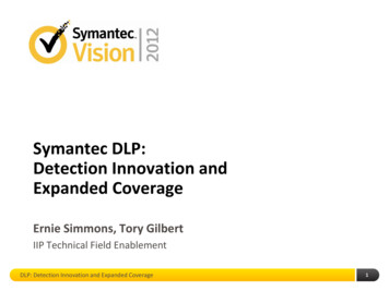
The results are to be included as another phase onto the existing Teradynecookbooks that past senior design groups have produced.1.3.2Problem solutionThe team has created a way to interface the required mixed-signal components with the Teradyne J750 via a socket and software test templateswritten using the IG-XL software that is compatible with the three differenttypes of devices required to test: a DAC, ADC, and a high speed operationalamplifier. The testing procedures along with the results will then be broughttogether in one concise package to be added on to the current Teradyne J750cookbook and will show users how to setup and test mixed-signal devicesusing the machine with the documented support.1.4Operational environmentOperation of the circuits has to occur indoors within a temperature rangeof 27 C to 33 C because of the sensitivity to temperature of the TeradyneJ750. Since the equipment itself is worth over 500,000 US dollars, a preventative process needs to be followed before operating the machine. Thus, theDepartment of Electrical and Computer Engineering will only operate andtest the various circuits for mixed-signal in a temperature regulated room.The presence of a human body presents the opportunity for the distribution of charge and voltage to any form of circuitry (i.e. ESD electrostaticdischarge), which can have an adverse affect on the equipment, perhaps causing permanent damage. It is required that every person that is present in theroom who is in direct contact with the Teradyne J750 wear ESD wrist bandswhen using the tester. This ESD wrist band is shown below in Figure 2.The vacuum pump and the lock portion of the lock/unlock switch areto be activated as shown in Figure 3 below before any form of testing canbe done. The purpose of the vacuum pump is to hold the DIB and thetester surface together firmly with approximately four PSI of pressure. Thepressure ensures that both interfaces are locked together so the other devicesthat need to be mounted are held in a stable position for the process oftesting.5
Figure 2: ESD wristbandFigure 3: Lock/Unlock switch on J750 tester6
1.5Intended user and intended useThis section defines who the intended users are and what the intended usesare for the project.1.5.1Intended userThe potential users for this project will be any student or faculty memberof the Department of Electrical and Computer Engineering who requires thetesting of the mixed-signal option devices. It can also be used as a laboratoryexperiment to re-enforce the concepts learned in various ECpE classes thatrelate to mixed-signal theory and industry applications.The user must possess knowledge of IC circuits, digital logic, signals,and digital communication; and have an understanding of the operation theTeradyne J750 for conducting tests. The user must be able to synchronizethe frequency that controls clock cycle along with the rest of setup and beable to follow the reference manual developed by the design team.1.5.2Intended useThe intended use of the project is to allow mixed-signal testing using theTeradyne J750 tester and to develop and test various scenarios for two different ADC's and DAC's (one ten-bit and one twelve-bit in both instances) aswell as for a 10 MHz or greater op-amp. This mixed-signal option providesan innovative approach to these microcontroller mixed-signal devices similar to the present industry testing capabilities and using the IG-XL softwareprovided is able to efficiently record the results from the tests so as to achievethe goals of the Electrical and Computer Engineering department.1.6Assumptions and limitationsThis section outlines the expected assumptions and limitations for the endproduct where any additional assumptions and limitations to be includedprior to team or advisor consultations about specifics of the project.1.6.1AssumptionsThis section provides the relevant details of the user and system assumptions.7
1.6.1.1 User assumptions This section outlines the assumptions aboutthe intended user: Willing and can follow basic instructions during training to use theequipment so as to follow all necessary safety precautions. User has read and understood the Teradyne J750 instructional manual. A suitable background in electrical and/or computer engineering. Previous experience in circuit testing with the Teradyne J750. User is knowledgeable of the electrical hazards the equipment can distribute and what the user is at risk of transferring to the machine. User treats and operates all equipment in a timely and professionalmanner. User is familiar with technical English as all documentation at presentis/will be written in English. User is knowledge about mixed-signal operation and concepts. User is able to tolerate the noise caused by the vacuum pumps.1.6.1.2 System assumptions This section outlines the assumptions aboutthe overall system: All instruments are operational and calibrated. No expired licenses or copyright material that the team does not havepermission to use. Present IG-XL codes can be modified for the required objectives. The vacuum pumps are always operational. Testing of DUT's are limited to one at a time. Teradyne J750 can interface with the IC devices to be tested. Reliable building power supply. No computer hardware failure.8
1.6.2LimitationsThis section will provide details of the limitations identified with the project: The Teradyne J750 is sensitive to temperature fluctuations and mustoperate within 3 C of the calibrated temperature. The current system is set for 30 C. The IG-XL software shall be used in writing the test code for the Teradyne J750. User has undergone some form of industry standard training as provided by Teradyne including the various training modules that are usedas reference materials. Modules on MSO are lengthy and can be regarded as a combinationof DSP, high speed testing, communication and signals, VLSI coursestaught presently at ISU all packed into one. Present IG-XL code exists for a 16-bit vocoder which is a combinedADC and DAC and no code exists for the required single ADC, DAC,and op-amp chips. Computer software issues with licensing for updated IG-XL software. Computer hardware problems issues due to failing components. Circuit breaker problems within the lab. Slow response time from CSG at ISU which introduces operationaldelay for testing the devices.1.7Expected end-product and other deliverablesThis section outlines the details of the expected end-product and other deliverables. The team expects to meet some of the specific tasks required in theform of the Expanded Cookbook Instructions for the Teradyne Integra J750Test System. The system developed to test the chosen devices are presentlynot on schedule and a demonstration test of one device will be done via thedeveloped cookbook for future users to test.At the conclusion of the spring 2007 semester, this project will produce:9
An expanded Teradyne J750 cookbook which documents mixed-signalIC circuits. A demo test of the finished 10-bit and 12-bit DAC device using theTeradyne J750.If the present computer software licensing issue is resolved this week, the10-bit and 12-bit ADC will also be added to the demo test.2Approach and product design resultsThe following section provides a detailed description of the end product design, approach and design results.2.1Approach usedThe following section contains details pertaining to the design objective,functional requirements, design constraints, technical approach considerations and results, and testing approach considerations.2.1.1Functional requirementsThe following section describes the functional requirements of the end product. The cookbook will be written on a level that the uninformed test engineer can understand The testing instructions will address two ADCs, two DACs, and anOp-amp faster than 10 MHz. Only one DUT will be tested at a time. A test program will be developed for each of the devices using IG-XLand will allow new devices of similar constraints to be added. Upon successful testing and mating of the devices a cookbook will bemade to allow future users to test these devices. If the project fails, proper documentation will be provided such thatone can look over potential problems and issues.10
2.1.2Design constraintsThe following section describes the design constraints for the end product. Limited to one software type on the Teradyne J750. The Teradyne J750uses IG-XL, which is essentially a Visual Basic and Excel platform. Theteam is limited to drawing user interfaces only in Basic. The operating conditions are limited to 30 C 3 C. As per the specification of the operating temperature, the lab temperature will be heldbetween 27 C and 33 C. The budget for the project is limited to 200.00. Since the cost of a new daughterboard is beyond the budget of thisproject, all the devices must fit in the 24-pin PDIP or 28-pin PLCCsockets currently available. The size of the daughterboard makes operation above 100 MHz highlysusceptible to capacitance and other transmission line effects. The Teradyne lab is only accessible by selected faculty members andstudents. Due to department rules and regulations, the team will only be ableto provide this product to selected faculty members and students whohave access to the Teradyne lab in 2129 Coover Hall. The user is aware of the Teradyne J750 and has used it prior to usingthis product. Also, the user will observe ESD precautions around theTeradyne J750 tester.2.1.3Technical approach considerations and resultsThe following section presents several possible technological alternatives analyzed during the design of this system along with their respective advantagesand disadvantages. In addition to this, the following section presents thetechnology selected for the final design as well as the technology used anddevices constructed by the May07 team.11
Figure 4: ZIF DIP Socket2.1.3.1 DIB mating The team has a daughter board with a 24-pin DIPsocket already wired in from a previous year's senior design team (Figure 4). Additionally, there is a daughter board that was included with Teradyne's Mixed-Signal Option (MSO) training program outfitted with two28-pin PLCC sockets.These daughter boards are used to mate the device under test to the DIB.Because of time and cost constraints, it was preferable to find a solutionusing the above devices. Listed below are some of the major advantages anddisadvantages of using the current daughter boards. The chips would be more expensive. This could become costly if a goodnumber of them burn out during tests. A great deal of time would be saved since there is no need for a newdaughter board or interface. One of the ZIF sockets is a 24-pin DIP. This configuration limits thechips to a maximum sampling rate of 700 MSBS, which might maketesting a slower process. The 28-pin PLCC socket enables much faster sampling rates, but mostof the devices in this package are obsolete, hard to obtain, and functionally limited. If a chip burns out it would be very easy to replace, thus saving time.12
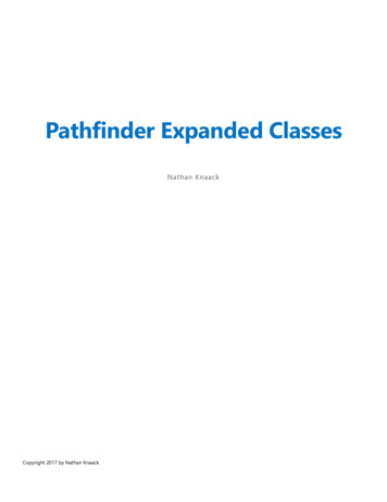
If the package were not considered, there would be a very wide varietyof devices available for test. This would include devices with much fastersampling times and many other unique options. There were three mainoptions for making the device compatible with the ZIF:Make a new daughter board Making a new daughter board wouldhave allowed much more flexibility in device selection. It would also haverequired a decent amount of time to assemble and would have cost significantly more than any of the other options. However, it is by far the cleanestand most durable choice.Create a printed circuit board that mates with the ZIF Depending on the design of the PCB it could have been very time consuming,but would have been cheaper than using a socket converter. De-solderingand re-soldering burned-out chips would have been a slow and potentiallydestructive process. However, a socket could have been used on the PCB,making switching chips easy. This option would not work with high-speeddevices because of design and manufacturing considerations for high-speedPCB's. There would have been almost absolute freedom in the choice ofdevices. This solution would not have worked with the PLCC sockets.Use a socket converter The socket converter was the fast and easysolution. The expense was still within the team's budget and was bothcheaper than creating a new daughter board and less time consuming thancreating a new interface.Figure 5: TSSOP to DIP socket converter13
A 24-pin TSSOP to DIP converter (Figure 5) was selected because almostall of the required devices were found in the 24-pin TSSOP package, thussimplifying testing and reducing the overall cost of the project. The twoop-amps that were found were compatible with the ZIF socket currentlyattached to a daughter board and the ADCs and DACs were all found in24-pin TSSOP packages. The only 24-pin TSSOP converter that could befound would only mate with a 600 mil ZIF socket and as a result, anotherZIF socket was purchased and installed on the double wide daughter board.2.1.4Testing approach considerationsThe testing plan consisted of two different approaches. The ADC and DACcircuits were to be tested for simple signal conversion with single- and multitone signals. Additionally, additional tests were to be done for linearity.The results were to be compared to the information given on the data sheet.The op-amps were also to be tested against various statistics given on thedata sheet, including but not limited to the -3dB bandwidth, the outputsaturation voltage, and transient response.Upon completion of the expanded cookbook, its effectiveness was to betested by allowing inexperienced undergraduate students to follow it to andperform a test on one of the devices. After this proof of usability, Dr. Weberwas to follow the cookbook and determine the effectiveness of the cookbook.The tests were all to be conducted in the Teradyne lab in Coover Hall.2.2Detailed designThe detailed design section of this report features a thorough description ofthe design of the IG-XL parameters, the DIB connections, and the deliverabledocumentation.2.2.1Overview of the project designAs previously stated, the purpose of this project was to create an expandedcookbook suitable for mixed signal testing, and to provide test scenariosand documentation for several common mixed signal devices. In order toaccomplish this, several specific design concepts were considered: IG-XL and Teradyne J750 functionality14
Device selection– Op-amp– ADC– DAC Deliverable documentation2.2.2IG-XL and Teradyne J750 functionalityThe IG-XL software is used to issue input and output commands to theTeradyne J750, in addition to providing signal generation and processingfunctions. The entire process is complicated but can be broken down into aset of simpler procedures.2.2.2.1 Channel and pin mapping Each of the pins on the DUT mustfirst be entered into the IG-XL software via the pin map worksheet. Eachpin must be given a name and assigned a type such as I/O, Analog, GND,or Power. This information can be found on the data sheet for each device.Descriptions of the pin types can be found in the Teradyne documentation.Next, each pin must be mapped to the channel to which it is connectedso that IG-XL can send or receive the appropriate data. The correct channelfor a given pin is entirely dependent on the design of the daughterboard andthe way the DUT connects to it.2.2.2.2 Specification sheets Each IG-XL program must have three different specification sheets: global, DC, and AC. Each sh
May 02, 2007 · Expanded “Cookbook” Instructions for the Teradyne Integra J750 Test System Final Report Team May 07-12 Client ECpE Department Faculty Advisor Dr. Weber . B Data sheet fo r OP 3 7 5 0 ii. C Data sheet fo r AD7 8 9 2 5 0 D Data sheet fo r A D 7 4 7 0 5 0 E Data sheet fo r