Transcription
file:///C fBuy: www.ValinOnline.com Phone 844-385-3099 Email: CustomerService@valin.com
MotortronicsTable of contents1About the Motortronics TE-RTD12 Relay Device . 21.1General . 21.2Dimensions and Mounting . 31.3General Wiring Diagram . 41.3.1Wire Size and Tightning Torque . 51.3.2CT Connection: Core Balance Connection . 51.3.3Ct Connection: Summing Method . 61.4Keypad . 71.4.1Layout and Description . 71.4.2Navigation . 81.5Quick Start-Up . 92Parameters . 112.1Parameters Overview .11-172.2Parameters Detailed Explanation . 182.2.1RTD Settings.18-272.2.2Digital Inputs . 282.2.3Analog Inputs . 292.2.4Analog Output . 322.2.5Device Setting . 3332.2.6Differential CTs . 332.2.7Relay Settings . 342.2.8Communication . 35Real Time Clock. 362.2.92.2.10 Display .37-382.2.11 Relay Configuration .38-392.2.12 System Settings . 392.2.13 Device Information . 403Fault History and Event Records . 413.1Fault History. 413.2Fault Code Table . 423.3Event Records . 434MODBUS RTU Communication . 444.1Serial Connection / Wiring . 444.2Serial Communication Settings . 454.3MODBUS RTU Message Structure .45-484.4Main Registers .49-544.5Monitor Registers. 55APPENDIX A: TECHNICAL SPECIFICATIONS . 56WARRANTY INFORMATION . 57Page 1Buy: www.ValinOnline.com Phone 844-385-3099 Email: CustomerService@valin.com
Motortronics1 About the Motortronics TE-RTD12 Relay Device1.1GeneralThe TE-RTD12 Relay device adds advanced RTD (Resistor Temperature Detector) and differential currentmonitoring capability to your new or existing motor system. The TE-RTD12 Relay device offers 12 built-in RTDinputs, 3 programmable output relays (5A), 2 isolated analog inputs (4-20mA), 1 isolated analog output (420mA), 3 isolated digital inputs and differential current feedback monitoring.Additionally, an RS485 (2 wire) communication port is available for use with a master device (PLC / SCADA /Operator Interface) for the purpose of programming and/or monitoring.Programmable relay outputs are provided that can be configured for a system function or for use as a globalAlarm or Trip based on temperature readout, which can be entered in ºC or ºF.A built-in event recorder stores fault history of past events with data points including Alarm / Trip Code, Current /Temperature value, Analog input value and Date / Time Stamp.The TE-RTD12 Relay device can be mounted on a back panel using the mounting bracket or DIN-Rail mount.NOTES -Page 2Buy: www.ValinOnline.com Phone 844-385-3099 Email: CustomerService@valin.com
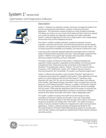
MotortronicsDimensions and .9)(225.0)(7.4)(133.3)(157.2)8.86” x 6.19” x 3.06” (H x W x D)225mm x 157.2mm x 77.7mm (H x W x D) (mm)MountingUse the designated mounting holes to mount the TE-RTD12 in the designated area of your system.Page 3Buy: www.ValinOnline.com Phone 844-385-3099 Email: CustomerService@valin.com
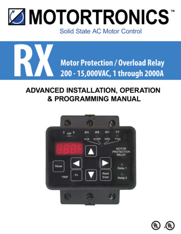
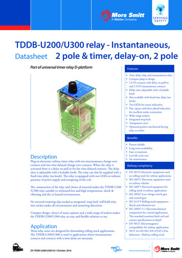
MotortronicsGeneral Wiring Diagram1.3The following figure shows the general wiring diagram for the TE-RTD12 Relay Device.The terminal blocks are removable (pluggable) for ease of wiring.Connector RJ45 Pin OutPinFunction4A 5A7ISO 5V thru 560Ω Resistor8ISO GndNote: Pin 7 and 8 can be used by the master device todetect the presence of a connected unit.CONTROLPOWER INPUT110 - 240 Vac1Ø 50 / 60 HzRELAY 1ECLNRELAY 2CN.O. N.C.CN.O. N.C.RJ45N.O. N.C.2345678910111223 456GND12ISOLATED4 – 20 mAOUTPUTISOLATED4 – 20 mAINPUTSISOLATEDDIGITALINPUTSRELAY 311Refer to section 4 fordetailed connections.IN1 COM 3IN2-OUT OUT-7897 81RS485COM PORT23456TB2TB1OKRefer to table 1. forrecommended terminaltorque values.ALARMRelay 1Note:TRIPRelay 2Relay 3ResetFn·RS485 and Digital Inputshave a common ground·All 4-20mA I/O share acommon ground that isisolated from the RS485and Digital I/O ground.EnterTE-RTD12 RelayTB712 A34 -5 B61-7C234GND GND S7 RET 7581RTD 11237TB489GND GND S8 RET 89RTD 8RTD 7DIFFERENTIALCT INPUTSTB364GND GND S1 RET 152TB5671112GND GND S9 RET 91109GND GND S2 RET 23101112GND GND S3 RET 3RTD 3234GND GND S10 RET 1051114234GND GND S4 RET 4RTD 4678GND GND S11 RET 1191012GND GND S12 RET 12RTD 11RTD 10RTD 98RTD 21055TB66712RTD 128GND GND S5 RET 5RTD 51196101112GND GND S6 RET 6RTD 6RTD TypicalConnectionsTE-RTD12 Relay Device General Wiring DiagramCAUTION: DO NOT CONNECT INPUT POWER TO TB2, TB3, TB4, TB5, TB6 or TB7ONLY CONNECT INPUT POWER TO TB1 TERMINAL N AND L (110 - 240Vac)Page 4Buy: www.ValinOnline.com Phone 844-385-3099 Email: CustomerService@valin.com
Motortronics1.3.1 Wire Size and Tightening TorqueTightening TorqueAWGTightening TorqueRecommended in-LbTB1, TB2, TB730 - 124.424.42TB3, TB430 - 142.212.21TB5, TB630 - 141.772.21ConnectorWire SizeMaximum in-LbTable 11.3.2 CT Connection: Core Balance ConnectionTB7123456DIFFERENTIALCT INPUTS AABC B CA PhaseMotorB PhaseC PhasePage 5Buy: www.ValinOnline.com Phone 844-385-3099 Email: CustomerService@valin.com
Motortronics1.3.3 CT Connection: Summing MethodTB7123456DIFFERENTIALCT INPUTS A B CABCA PhaseA PhaseMotorB PhaseB PhaseC PhaseC PhasePage 6Buy: www.ValinOnline.com Phone 844-385-3099 Email: CustomerService@valin.com
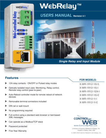
Motortronics1.4Keypad1.4.1 Layout and DescriptionThe Keypad for the TE-RDT12 Relay incorporates an 8 digit LED display, a membrane keypad forprogramming, data entry and data retrieval. There are also 6 LED status indicators.OKALARMRelay 1TRIPRelay 2Relay 3ResetFnEnterTE-RTD12 RelayTE- RTD12 KeypadKeypad DescriptionKeysDisplayLEDResetResets the device after the conditions that cause anALARM or TRIP have been clearedFnEnter program mode (view event log)Up and Down ArrowsMonitor Navigation / increase or decrease valueRight and Left ArrowsEach key press shifts the active (flashing) digit to the rightor left by one position, allowing you to change highervalues of functions without waiting to Auto-step throughlarge numbers.EnterRead and save parameter changes8888 8888Two 4-digit 7-segment LED displaysOK (Green)ON: Indicates that there are no Alarms or Trips.(Yellow and Red LED’s are OFF)ALARM (Yellow)ON: An ALARM is activeTRIP (Red)ON: A TRIP has occurredRelay 1 (Yellow)Relay 2 (Yellow)ON: Relay is activatedRelay 3 (Yellow)Table 2Page 7Buy: www.ValinOnline.com Phone 844-385-3099 Email: CustomerService@valin.com
Motortronics1.4.2 NavigationPower UpSelectManual SelectProgram ModeEvent Log ModeFnMain Monitor#1 Hottest Stator RTD # (id)#2 Hottest Stator RTD temperature#3 Hottest Non-Stator RTD # (id)#4 Hottest Non-Stator RTD temp.#5 RTD #1 (default name: Stator #1)#6 RTD #2 (default name: Stator t / Switch# and ValueEnter . See parameter F094SelectAuto-Scroll#15#16 See parameter F094ResetFault/AlarmPage 8Buy: www.ValinOnline.com Phone 844-385-3099 Email: CustomerService@valin.com
MotortronicsQuick Start-up1.5Follow these steps to setup your TE-RTD12 device.Step 1: Connect Power SupplyWith the power-supply turned OFF connect a single phase power supply 110 – 240 Vac Nominal to terminal TB1(1 Ground, 2 N, 3 L) to power the TE-RTD12. See wiring diagram for connections.CONTROLPOWER INPUT110 to 240 Vac1Ø 50 / 60 HzTB1RELAY 1Earth GndE1CLN2RELAY 2N.O. N.C.CRELAY 3CN.O. N.C.N.O. N.C.3TB1Important: Use fuse protection of 2A 240VAC 5kA RK5 or equivalent fuse for the input power supply.CAUTION: DO NOT CONNECT INPUT POWER TO TB2, TB3, TB4, TB5, TB6 or TB7ONLY CONNECT INPUT POWER TO TB1 TERMINAL N AND L (85 265Vac)Step 2: Connect RTD Inputs (only if used)-Turn power-supply OFFWith the power-supply turned OFF connect the RTD inputs to terminal block TB3, TB4, TB5 and TB6according to the wiring diagram.-TB4TB317234GND GND S7 RET 7586789109GND GND S8 RET 812GND GND S9 RET 9RTD 8RTD 711110234GND GND S10 RET 105611GND GND S11 RET 11RTD 11234GND GND S1 RET 1526910121112GND GND S12 RET 12RTD 12TB6TB518RTD 11RTD 10RTD 9778GND GND S2 RET 2RTD 291031112GND GND S3 RET 3RTD 314234GND GND S4 RET 4RTD 456578GND GND S5 RET 5RTD 591061112GND GND S6 RET 6RTD 6RTD TypicalConnectionsNOTE: The stator RTD’s have to connected consecutively from RTD #1 and up. The number of stator RTD’s hasto be entered in parameter F049.Page 9Buy: www.ValinOnline.com Phone 844-385-3099 Email: CustomerService@valin.com
MotortronicsStep 3: Program Unit- Turn on power-supply.- Set parameter F049 to # of used stator RTD’s.- To use temperature setting/readout in Fahrenheit, enter level 2 password (F102) 2000, then setparameter F095 to ‘1’ (default Fahrenheit).- Set Real-time clock Date and Time, parameter F088 to F093.- Enable RTD inputs 1 - 12 if used parameter F001, F005, F009, F013, F017, F021, F025, F029, F033,F037, F41 and F45.- Set Alarm and Trip levels for RTD inputs F003, F004.F007, F008.F011, F012.Page 10Buy: www.ValinOnline.com Phone 844-385-3099 Email: CustomerService@valin.com
Motortronics2.0 Parameters2.1 Parameter OverviewGrpRTD#Fn#FunctionF001 STATOR PHASE A1 TYPEF002 RTD # 1 DESCRIPTIONRTD11. RTD Settings.RTD2RTD3RTD4Adj. Range0-4 [0: OFF; 1: 100 Ohm Pt; 2: 10 Ohm Cu;3: 100 Ohm Ni; 4: 120 Ohm Ni.]0 –10: Stator #1 (StA1)1: RTD #1 (rt 1)STATOR PHASE A1F003 ALARM0-464,[0-240 (C); 32-464 (F)], OFFTEMPERATURESTATOR PHASE A1 TRIPF0040-464,[0-240 (C); 32-464 (F)], OFFTEMPERATURE0-4 [0: OFF; 1: 100 Ohm Pt; 2: 10 Ohm Cu;F005 STATOR PHASE A2 TYPE3: 100 Ohm Ni; 4: 120 Ohm Ni.]0 –1F006 RTD # 2 DESCRIPTION0: Stator #2 (StA2)1: RTD #2 (rt 2)STATOR PHASE A2F007 ALARM0-464,[0-240 (C); 32-464 (F)], OFFTEMPERATURESTATOR PHASE A2 TRIPF0080-464,[0-240 (C); 32-464 (F)], OFFTEMPERATURE0-4 [0: OFF; 1: 100 Ohm Pt; 2: 10 Ohm Cu;F009 STATOR PHASE A3 TYPE3: 100 Ohm Ni; 4: 120 Ohm Ni.]0 –1F010 RTD # 3 DESCRIPTION0: Stator #3 (StA3)1: RTD #3 (rt 3)STATOR PHASE A3F011 ALARM0-464,[0-240 (C); 32-464 (F)], OFFTEMPERATURESTATOR PHASE A3 TRIPF0120-464,[0-240 (C); 32-464 (F)], OFFTEMPERATURE0-4 [0: OFF; 1: 100 Ohm Pt; 2: 10 Ohm Cu;F013 STATOR PHASE A4 TYPE3: 100 Ohm Ni; 4: 120 Ohm Ni.]0 –1F014 RTD # 4 DESCRIPTION0: Stator #4 (StA4)1: RTD #4 (rt 4)STATOR PHASE A4F015 ALARM0-464,[0-240 (C); 32-464 (F)], OFFTEMPERATURESTATOR PHASE A4 TRIPF0160-464,[0-240 (C); 32-464 (F)], 1011OFF11OFF1Note: See parameter Fn95 first to change between ºC and ºF.Page 11Buy: www.ValinOnline.com Phone 844-385-3099 Email: CustomerService@valin.com
MotortronicsGrpRTD#Fn#FunctionF017 STATOR PHASE A5 TYPEF018 RTD # 5 DESCRIPTIONRTD51. RTD Settings.RTD6RTD7RTD8Adj. Range0-4 [0: OFF; 1: 100 Ohm Pt; 2: 10 Ohm Cu;3: 100 Ohm Ni; 4: 120 Ohm Ni.]0 –10: Stator #5 (StA5)1: RTD #5 (rt 5)STATOR PHASE A5F019 ALARM0-464,[0-240 (C); 32-464 (F)], OFFTEMPERATURESTATOR PHASE A5 TRIPF0200-464,[0-240 (C); 32-464 (F)], OFFTEMPERATURE0-4 [0: OFF; 1: 100 Ohm Pt; 2: 10 Ohm Cu;F021 STATOR PHASE A6 TYPE3: 100 Ohm Ni; 4: 120 Ohm Ni.]0 –1F022 RTD # 6 DESCRIPTION0: Stator #6 (StA6)1: RTD #6 (rt 6)STATOR PHASE A6F023 ALARM0-464,[0-240 (C); 32-464 (F)], OFFTEMPERATURESTATOR PHASE A6 TRIPF0240-464,[0-240 (C); 32-464 (F)], OFFTEMPERATURE0-4 [0: OFF; 1: 100 Ohm Pt; 2: 10 Ohm Cu;F025 FRONT BEARING TYPE3: 100 Ohm Ni; 4: 120 Ohm Ni.]0 –1F026 RTD # 7 DESCRIPTION0: Front Bearing (Fb)1: RTD #7 (rt 7)FRONT BEARING ALARMF0270-464,[0-240 (C); 32-464 (F)], OFFTEMPERATUREFRONT BEARING TRIPF0280-464,[0-240 (C); 32-464 (F)], OFFTEMPERATURE0-4 [0: OFF; 1: 100 Ohm Pt; 2: 10 Ohm Cu;F029 REAR BEARING TYPE3: 100 Ohm Ni; 4: 120 Ohm Ni.]0 –1F030 RTD # 8 DESCRIPTION0: Rear Bearing (rb)1: RTD #8 (rt 8)REAR BEARING ALARMF0310-464,[0-240 (C); 32-464 (F)], OFFTEMPERATUREREAR BEARING TRIPF0320-464,[0-240 (C); 32-464 (F)], 1011OFF11OFF1Note: See parameter Fn95 first to change between ºC and ºF.Page 12Buy: www.ValinOnline.com Phone 844-385-3099 Email: CustomerService@valin.com
MotortronicsGrpRTD#Fn#F033 RTD #9 TYPEF034 RTD #9 DESCRIPTIONRTD9RTD #9 ALARMTEMPERATURERTD #9 TRIPF036TEMPERATUREF035F037 RTD #10 TYPEF038 RTD #10 DESCRIPTIONRTD10RTD #10 ALARMTEMPERATURERTD #10 TRIPF040TEMPERATURE1. RTD Settings.F039F041 RTD #11 TYPEF042 RTD #11 DESCRIPTIONRTD11RTD #11 ALARMTEMPERATURERTD #11 TRIPF044TEMPERATUREF043F045 RTD #12 TYPEF046 RTD #12 DESCRIPTIONRTD12RTD #12 ALARMTEMPERATURERTD #12 TRIPF048TEMPERATURE# OF RTD’S USED FORF049STATORF050 RTD ,[0-240 (C); 32-464 (F)], OFF1OFF10-464,[0-240 (C); 32-464 (F)], OFF1OFF11OFF11010-464,[0-240 (C); 32-464 (F)], OFF1OFF10-464,[0-240 (C); 32-464 (F)], OFF1OFF11OFF11010-464,[0-240 (C); 32-464 (F)], OFF1OFF10-464,[0-240 (C); 32-464 (F)], OFF1OFF11OFF11010-464,[0-240 (C); 32-464 (F)], OFF1OFF10-464,[0-240 (C); 32-464 (F)], OFF1OFF10-6160 – 1 [0 Disabled, 1 Enabled]10Adj. RangeFunction0-4 [0: OFF; 1: 100 Ohm Pt; 2: 10 Ohm Cu;3: 100 Ohm Ni; 4: 120 Ohm Ni.]0 –10: Bearing Box (brbo)1: RTD #9 (rt 9)0-4 [0: OFF; 1: 100 Ohm Pt; 2: 10 Ohm Cu;3: 100 Ohm Ni; 4: 120 Ohm Ni.]0 –10: Ambient (Abnt)1: RTD #10 (rt10)0-4 [0: OFF; 1: 100 Ohm Pt; 2: 10 Ohm Cu;3: 100 Ohm Ni; 4: 120 Ohm Ni.]0 –10: User Defined #1 (USr1)1: RTD #11 (rt11)0-4 [0: OFF; 1: 100 Ohm Pt; 2: 10 Ohm Cu;3: 100 Ohm Ni; 4: 120 Ohm Ni.]0 –10: User Defined #2 (USr2)1: RTD #12 (rt12)1Note: See parameter Fn95 first to change between ºC and ºF.Page 13Buy: www.ValinOnline.com Phone 844-385-3099 Email: CustomerService@valin.com
MotortronicsGrpRTD#Fn#2. Digital InputsF051 Input #1 (InP1) SelectF052 Time DelayF053 Input #2 (InP2) SelectF054 Time DelayF055 Input #3 (InP3) SelectF056 Time DelayF057 Analog Input #1 NameF058F0593. Analog InputsF060F061F062F063Analog Input #1 (AnA1)4mAAnalog Input #1 (AnA1)20mAAnalog Input #1 AlarmLevelAnalog Input #1 Alarm TimeDelayAnalog Input #1 Trip LevelAnalog Input #1 Trip TimeDelayF064 Analog Input #2 NameF065F066F067F068F069Adj. RangeFunctionAnalog Input #2 (AnA2)4mAAnalog Input #2 (AnA2)20mAAnalog Input #2 AlarmLevelAnalog Input #2 Alarm TimeDelayAnalog Input #2 Trip Level0-2 [0: Disabled; 1: Normally Open; 2:Normally Closed]1-60 (Sec)0-2 [0: Disabled; 1: Normally Open; 2:Normally Closed]1-60 (Sec)0-2 [0: Disabled; 1: Normally Open; 2:Normally Closed]1-60 0-5[0: OFF;1: Analog Input #1 (AnA1);2: Oscillation #1 (oSC1);3: Air Flow #1 (AFL1);4: Speed #1 (SPd1);5: Pressure #1 (PrS1).]1OFF10-99991010-99991999910,1-9999 [0: OFF; 1-9999 trip level]1OFF11-60 (Sec)1110,1-9999 [0: OFF; 1-9999 trip level]1OFF11-60 (Sec)1110-5[0: OFF;1: Analog Input #2 (AnA2);2: Oscillation #2 (oSC2);3: Air Flow #2 (AFL2);4: Speed #2 (SPd2);5: Pressure #2 (PrS2).]1OFF10-99991010-99991999910,1-9999 [0: OFF; 1-9999 trip level]1OFF11-60 (Sec)1110,1-9999 [0: OFF; 1-9999 trip level]1OFF1Note: See parameter Fn95 first to change between ºC and ºF.Page 14Buy: www.ValinOnline.com Phone 844-385-3099 Email: CustomerService@valin.com
MotortronicsGrpRTD#Incr.DefaultSettingPSWLevel1-60 (Sec)111F071 Analog Output0-6[0: OFF;1: Hottest Stator RTD Temperature;2. Hottest Non-Stator RTD Temperature;3. Analog Input #1 (AnA1);4: Analog Input #2 (AnA2);5: Unit Internal Temperature;6: Highest Differential Phase Current. ]1OFF1F072 Analog Output 4mA0-9999101F073 Analog Output 20mA0-99990-257[1-125(C), 32-257(F),OFF]1999911501----OFF, 5-90 (% of CT Primary)5OFF11-60 (Sec)Fn#9. RTC8. Comm.7. Relay Settings6. Differential CTs5. DeviceSetting4. Analog OutputF070F074Adj. RangeFunctionAnalog Input #2 TripTime DelayUnit Internal AlarmTemperatureF075 ReservedDifferential CT AlarmF076LevelF077 Alarm Time Delay111F078 Differential CT Trip Level OFF, 5-90 (% of CT Primary)5OFF1F079 Trip Time Delay1-60 (Sec)111F080 Differential CT PrimaryDifferential CTF081SecondaryOFF, 5-2000 (A)5OFF21,5 (A)452F082 Relay 1 settingOperation # 19 only1F083 Relay 2 settingOperation # 1 – 191F084 Relay 3 settingOperation # 1 – 191F085 Communications0-2 [0 OFF;1 Enabled(11bit) communication only;2 Enabled(10bit) comm. only;]1OFF2F086 Baud Rate9.6, 19.2 and 38.4-9.62F087 Modbus Address1 - 247112F088 Year2000 - 2047F089 Month1-12F090 DayF091 HourF092 MinuteF093 Seconds19 (AnyTrip)9 (AnyAlarm)13(DigitalInput #1Trip)1111 Year-11 Month-11-311 Day-10 - 231 Hour-10 - 591 Min.-10 - 591 Sec.-1Note: See parameter Fn95 first to change between ºC and ºF.Page 15Buy: www.ValinOnline.com Phone 844-385-3099 Email: CustomerService@valin.com
Motortronics11. Relay config.10. DisplayGrpRTD#Fn#12. System SettingsIncr.DefaultSettingPSWLevelF094 Default Display0-34 [0: Auto Scroll RTD Screens; 1-34: SeeTable of this Function]112F095 Unit of Temperature0-1 [0: C Celsius; 1: F Fahrenheit.]102F096 Relay 1 Fail Safe0-1 [0 Disabled; 1 Enabled.]102F097 Relay 2 Fail Safe0-1 [0 Disabled; 1 Enabled.]102F098 Relay 3 Fail Safe0-1 [0 Disabled; 1 Enabled.]0-3[0 Disabled;1 Energize Relay #1 for 5 seconds;2 Energize Relay #2 for 5 seconds;3 Energize Relay #3 for 5 seconds;]10210210(Showencrypted code)11012-F099 Relay TestF10013. Rev.Adj. RangeFunctionParameter Lock/ Level 1 0, 001 – 999 [0 Disabled,PasswordNumber Password]0, 1 – 4 [0 Disabled;1 Clear Highest Temperature.2 Reset Factory Default Settings inSystem Clear / Factorycategory of Level 1 Password. Level 1F101 Reset (TBD) (ResetFactory Default Settings) Password required.3 Reset Factory Default Settings incategories of Level1 and Level 2 Password.Level 2 Password required.4 Reserved. ]F102 Level 2 Password2000 – 999912000(Showencrypted code)F103 Reserved---F104 RTD12 Revision #---F105 KP Revision #---F106 RTD-INF Revision #---Note: See parameter Fn95 first to change between ºC and ºF.Page 16Buy: www.ValinOnline.com Phone 844-385-3099 Email: CustomerService@valin.com
MotortronicsGrpRTD#Fn#Fault History #1, LatestFaultAlarm / Trip Level (ifF108available)F107F109 Time Stamp, Fault #114. Fault HistoryF110 Date Stamp, Fault #1Fault History #2,Previous FaultAlarm / Trip Level (ifF112available)F111F113 Time Stamp, Fault #2F114 Date Stamp, Fault #2Fault History #3, OldestFaultAlarm / Trip Level (ifF116available)F115F117 Time Stamp, Fault #3F118 Date Stamp, Fault #315. Event RecordF119Adj. RangeIncr.DefaultSetting0, 31 – 50 (Fault #: see Fault code list; 0: Nofault 0.0101.0110--00.0100.0000.0101.01FunctionPresent Event RecordNumberSelect Event RecordF120 Number[tonavigate the record]F121 Fault CodeF122Alarm / Trip Level (ifavailable)F123Time Stamp of SelectedEvent RecordF124Date Stamp of SelectedEvent RecordEST 00.00-23.59 (hh.mm)[hh 00-23; mm 00-59]01.01 – 12.31 (MM.DD)[MM 01-12; DD 01-31]0, 31 – 50 (Fault #: see Fault code list; 0: Nofault history)--EST 00.00-23.59 (hh.mm)[hh 00-23; mm 00-59]01.01 – 12.31 (MM.DD)[MM 01-12; DD 01-31]0, 31 – 50 (Fault #: see Fault code list; 0: Nofault history)--EST 00.00-23.59 (hh.mm)[hh 00-23; mm 00-59]01.01 – 12.31 (MM.DD)[MM 01-12; DD 01-31]0-447 [0: Null Rec; Others 1 – 447: Rec ofCycling Buffer. 4 parameters per Rec]1-447 [Point to the Rec in Cycling Buffer.Total 447 Rec. 4 parameters per Rec]PSWLevel2st1 parameter in Rec. (See Fault Code List forfault code definitions.)2ndrd3 : 00.00-23.59 (hh.mm)[hh 00-23; mm 00-59]th4 (last): 01.01 – 12.31 (MM.DD)[MM 01-12; DD 01-31]Note: See parameter Fn95 first to change between ºC and ºF.Table 3Page 17Buy: www.ValinOnline.com Phone 844-385-3099 Email: CustomerService@valin.com
Motortronics2.2 Parameter Detailed Explanation2.2.1 RTD SettingsF001 - STATOR PHASE A1 TYPE SELECTION (0 – 4), Default Setting: 0 - OFFSelect RTD #1 TypeSetting01234TypeOFF100 Ohm Pt (Platinum RTD)10 Ohm Cu (Copper RTD)100 Ohm Ni (Nickel RTD)120 Ohm Ni (Nickel RTD)F002 - RTD #1 DESCRIPTION SELECTIONSelect RTD Description Selection (0 – 1), Default Setting: 0 – Stator #1 (StA1)Setting01AssignmentStator #1 (StA1)RTD #1 (rt 1)F003 - RTD #1 STATOR PHASE A1 ALARM TEMPERATURE (0 – 464), Default Setting: OFFSet RTD Temperature Alarm Level. When the RTD temperature reached this level Alarm “ALAr St 1” or“ALAr rt 1” is shown on the keypad display. The Level can be programmed in Celsius or Fahrenheit dependingon the setting of F095.Range 0 – 240 Degrees Celsius (F095 0)Range 32 – 464 Degrees Fahrenheit (F095 1)F004 - RTD #1 STATOR PHASE A1 TRIP TEMPERATURE (0 – 464), Default Setting: OFFSet RTD Temperature trip Level. When the RTD temperature reached this level trip “triP St 1” or “triP rt 1” isshown on the keypad display. The Level can be programmed in Celsius or Fahrenheit depending on the settingof F095.Range 0 – 240 Degrees Celsius (F095 0)Range 32 – 464 Degrees Fahrenheit (F095 1)Page 18Buy: www.ValinOnline.com Phone 844-385-3099 Email: CustomerService@valin.com
MotortronicsF005 - STATOR PHASE A1 TYPE SELECTION (0 – 4), Default Setting: 0 - OFFSelect RTD #2 TypeSetting01234TypeOFF100 Ohm Pt (Platinum RTD)10 Ohm Cu (Copper RTD)100 Ohm Ni (Nickel RTD)120 Ohm Ni (Nickel RTD)F006 - RTD #2 DESCRIPTION SELECTIONSelect RTD Description Selection (0 – 1), Default Setting: 0 – Stator #2 (StA2)Setting01AssignmentStator #2 (StA2)RTD #2 (rt 2)F007 - RTD #2 STATOR PHASE A2 ALARM TEMPERATURE (0 – 464), Default Setting: OFFSet RTD Temperature Alarm Level. When the RTD temperature reached this level Alarm “ALAr St 2” or“ALAr rt 2” is shown on the keypad display. The Level can be programmed in Celsius or Fahrenheit dependingon the setting of F095.Range 0 – 240 Degrees Celsius (F095 0)Range 32 – 464 Degrees Fahrenheit (F095 1)F008 - RTD #2 STATOR PHASE A2 TRIP TEMPERATURE (0 – 464), Default Setting: OFFSet RTD Temperature trip Level. When the RTD temperature reached this level trip “triP St 2” or “triP rt 2”isshown on the keypad display. The Level can be programmed in Celsius or Fahrenheit depending on the settingof F095.Range 0 – 240 Degrees Celsius (F095 0)Range 32 – 464 Degrees Fahrenheit (F095 1)F009 - STATOR PHASE A3 TYPE SELECTION (0 – 4), Default Setting: 0 - OFFSelect RTD #3 TypeSetting01234TypeOFF100 Ohm Pt (Platinum RTD)10 Ohm Cu (Copper RTD)100 Ohm Ni (Nickel RTD)120 Ohm Ni (Nickel RTD)Page 19Buy: www.ValinOnline.com Phone 844-385-3099 Email: CustomerService@valin.com
MotortronicsF010 - RTD #3 DESCRIPTION SELECTIONSelect RTD Description Selection (0 – 1), Default Setting: 0 – Stator #3 (StA3)Setting01AssignmentStator #3 (StA3)RTD #3 (rt 3)F011 - RTD #3 STATOR PHASE A3 ALARM TEMPERATURE (0 – 464), Default Setting: OFFSet RTD Temperature Alarm Level. When the RTD temperature reached this level Alarm “ALAr St 3” or“ALAr rt 3”is shown on the keypad display. The Level can be programmed in Celsius or Fahrenheit dependingon the setting of F095.Range 0 – 240 Degrees Celsius (F095 0)Range 32 – 464 Degrees Fahrenheit (F095 1)F012 - RTD #3 STATOR PHASE A3 TRIP TEMPERATURE (0 – 464), Default Setting: OFFSet RTD Temperature trip Level. When the RTD temperature reached this level trip “triP St 3” or “triP rt 3” isshown on the keypad display. The Level can be programmed in Celsius or Fahrenheit depending on the settingof F095.Range 0 – 240 Degrees Celsius (F095 0)Range 32 – 464 Degrees Fahrenheit (F095 1)F013 - STATOR PHASE A4 TYPE SELECTION (0 – 4), Default Setting: 0 - OFFSelect RTD #4 TypeSetting01234TypeOFF100 Ohm Pt (Platinum RTD)10 Ohm Cu (Copper RTD)100 Ohm Ni (Nickel RTD)120 Ohm Ni (Nickel RTD)F014 - RTD #4 DESCRIPTION SELECTIONSelect RTD Description Selection (0 – 1), Default Setting: 0 – Stator #4 (StA4)Setting01AssignmentStator #4 (StA4)RTD #4 (rt 4)F015 - RTD #4 STATOR PHASE A4 ALARM TEMPERATURE (0 – 464), Default Setting: OFFSet RTD Temperature Alarm Level. When the RTD temperature reached this level Alarm “ALAr St 4” or“ALAr rt 4”is shown on the keypad display. The Level can be programmed in Celsius or Fahrenheit dependingon the setting of F095.Range 0 – 240 Degrees Celsius (F095 0)Range 32 – 464 Degrees Fahrenheit (F095 1)Page 20Buy: www.ValinOnline.com Phone 844-385-3099 Email: CustomerService@valin.com
MotortronicsF016 - RTD #4 STATOR PHASE A4 TRIP TEMPERATURE (0 – 464), Default Setting: OFFSet RTD Temperature trip Level. When the RTD temperature reached this level trip “triP St 4” or “triP rt 4”isshown on the keypad display. The Level can be programmed in Celsius or Fahrenheit depending on the settingof F095.Range 0 – 240 Degrees Celsius (F095 0)Range 32 – 464 Degrees Fahrenheit (F095 1)F017 - STATOR PHASE A5 TYPE SELECTION (0 – 4), Default Setting: 0 - OFFSelect RTD #5 TypeSetting01234TypeOFF100 Ohm Pt (Platinum RTD)10 Ohm Cu (Copper RTD)100 Ohm Ni (Nickel RTD)120 Ohm Ni (Nickel RTD)F018 - RTD #5 DESCRIPTION SELECTIONSelect RTD Description Selection (0 – 1), Default Setting: 0 – Stator #5 (StA5)Setting01AssignmentStator #5 (StA5)RTD #5 (rt 5)F019 - RTD #5 STATOR PHASE A5 ALARM TEMPERATURE (0 – 464), Default Setting: OFFSet RTD Temperature Alarm Level. When the RTD temperature reached this level Alarm “ALAr St 5” or“ALAr rt 5”is shown on the keypad display. The Level can be programmed in Celsius or Fahrenheit dependingon the setting of F095.Range 0 – 240 Degrees Celsius (F095 0)Range 32 – 464 Degrees Fahrenheit (F095 1)F020 - RTD #5 STATOR PHASE A5 TRIP TEMPERATURE (0 – 464), Default Setting: OFFSet RTD Temperature trip Level. When the RTD temperature reached this level trip “triP St 5” or “triP rt 5”isshown on the keypad display. The Level can be programmed in Celsius or Fahrenheit depending on the settingof F095.Range 0 – 240 Degrees Celsius (F095 0)Range 32 – 464 Degrees Fahrenheit (F095 1)Page 21Buy: www.ValinOnline.com Phon
Motortronics Page 1 Table of contents . 1. . system function or for use as a global Alarm or Trip based on temperature readout, which can be entered in ºC or ºF. A built-in event recorder stores fault history of past events with data points including Alarm / Trip Code, Current /