Transcription
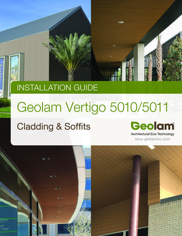
INSTALLATION GUIDEGeolam Vertigo 5010/5011Cladding & Soffitswww.geolaminc.com
Vertigo 5010WHS: Wood hybrid systemDatasheetThickness: 13 mm 1 2 inTotal width: 185 mm 7 in14Usable width: 170 mm 6 1 2 inSecondary moment lx (cm4): 0.56Secondary moment ly (cm4): 121.55Section tolerances in mm: 0.5 / - 1.5Section modulus Zx (cm3): 0.68Fire rating:Section modulus Zy (cm3): 12.81ASTM E-84 Class A / ASTM E-84 Class BCore in anodized aluminum alloy:Surfaces finish: sandedA6063S-T5Standard length: 3.65 m 12 ftCoefficient of Thermal Expansion:Or order any length from:2.45 m 8 ft to 5.48 m 18 ft(20-100 C) : 23.4 µm/m/ CWeight: 1.19 kg/lm 0.80 lb/ftModulus of Elasticity: 68.6 GPaTensile Strength: 186 Mpa minCore cross section (mm2): 371.95Colors:TeakMoleskinRosewoodEbony2
Vertigo 5011WHS: Wood hybrid systemDatasheetThickness: 13 mm 1 2 inTotal width: 130 mm 5 in18Usable width: 110 mm 4 1 3 inSecondary moment lx (cm4): 0.56Secondary moment ly (cm4): 121.55Section tolerances in mm: 0.5 / - 1.5Section modulus Zx (cm3): 0.68Fire rating:Section modulus Zy (cm3): 12.81On request before orderCore in anodized aluminum alloy:Surfaces finish: sandedA6063S-T5Standard length: 3.65 m 12 ftCoefficient of Thermal Expansion:Or order any length from:2.45 m 8 ft to 5.48 m 18 ft(20-100 C) : 23.4 µm/m/ CWeight: 0.77 kg/lm 0.52 lb/ftModulus of Elasticity: 68.6 GPaTensile Strength: 186 Mpa minCore cross section (mm2): 371.95Colors:TeakMoleskinRosewoodEbony3
Vertigo 5010 / 5011WHS: Wood hybrid systemDatasheetDrainagePlaneadvisedOUTSIDE CORNER TRIM2. Geolam boards can be mounted/ ”/ 14 mm3 mmhorizontally, vertically,or/ ”/diagonallydirectly onto the wall. Over codecompliant AVB.11281”/ 25 mm2”/ 50 mm3. Boards may be ripped (cut alongtheir length) as needed./2”/ 14 mm114. Recommended screws are stainlesssteel, with an austenitic structure andnon-magnetic. Recommended screwdiameter is 4 mm, pan head with adiameter of 8.2 mm and length of19 mm. Maximum 24”o.c.5. We recommend leaving a 3 mm (1/8”)gap between butt ends to allow forexpansion/contraction in response tochanges in temperature. However, ifyour design calls for zero-spaced buttjoints, please refer to Page 9.6. The boards may be miter-cut foroutside corners or Geolam O/Scorners may be used.6. Exposed screws on the final board maybe covered with caulking if desired orour color-matched 2-piece starter/’J’trim as shown below./8”/ 3 mm1”/ 25 mm2”/ 50 mm2-Piece Starter (J-trim) 9321J TRIM (2-PIECE STARTER STRIP)/4”/ 5 mm11 1/4”/ 30 mm/2”/ 14 mm1/4”/ 20 mmOUTSIDE CORNERTRIMOutsideCorner9322/2”/ 14 mm1/8”/ 3 mm2”/ 50 mm11”/ 25 mmMaximum 12 mm 7 16 inMinimum 3 mm 1 8 in1. Weeping of condensation and aircirculation are essential to the healthof building products. Allthough theboards can be mounted directlyonto the wall or substrate, it is goodbuilding practice to install a drainageplane and mount onto that. Do notseal the top nor bottom of the wall toallow for drainage and air circulation.3DrainagePlaneadvised/2”/ 14 mm11/8”/ 3 mm1”/ 25 mm2”/ 50 mm4
Vertigo 5010 / 5011Installation of J-trim/4”/ 5 mmPartAAof the J-trim to the wall as1. Fasten Partshown (ss screws recommended)ClipVertigoVertigo5010 5010A Part AVerPart AVertigo 532go 501011 1/4”/ 30 mm/4”/ 5 mm/4”/ 20 mm1 1/4”/ 30 mm1‘Part B’3/2”/ 14 mm/16”11 mm3/4”/ 20 mm7/2”/ 14 mm/16”11 mm71‘Clip’‘Part A’‘Part B’‘Clip’1‘Part A’1ClipPart B Part BClip2. S crew the Geolam Vertigo board throughthe J-trim into the wall every 24”Part B43. Attach the metal clips onto Part B every16” (40 cm) as shown5Part A Part APart B Part BVertigo 5010Part APart BClipPart B4. W ith a rubber mallet tap Part B into Part A5. Final assembled J-trim5
advisedadvised1. I nstall 2-Piece Starter/”J” or other trimcomponent at top and bottom of wall (A)2. I f outside corners are not mitered, installOutside Corners before cladding (F)AMaximum 12 mm 7 16 inCladding InstallationMinimum 3 mm 1 8 inVertigo 5010 / 5011B3. I nstall top course first panel and screw atmaximum 24” (B)Drainage rainagePlaneadvised6. C ut last panel as needed to fit into “J”/Starter Trim and secure (E)DrainagePlaneEadvisedGIMaximum 12 mm 7 16 Maximumin12 mm 7 16 inMinimum 3 mm 1 8 inMinimum 3 mm 1 8 inMinimum 3 mm 1 8 ininMaximum 12 mm 7 16Maximum12 mm 7 16 in4. Install adjacent panels leaving 1/8” or 3mmbetween butt jointsMaximum 12 mm 7 16 in3. S lide adjacent panels with selected jointreveal gap and secure (I)Minimum 3 mm 1 8 in Minimum 3 mm 1 8 in2. I nstall first course into trim component andsecure into place (H)DrainagePlaneadvised1. I nstall 2-Piece Starter/”J” at perimeterterminations (G)Maximum 12 mm 7 16 inDrainageadvisedMinimumPlane 3 mm 1 8 inSoffit InstallationDrainagePlaneadvisedDrainage DrainagePlanePlaneadvised advisedDrainagePlaneadvisedMinimum 3 mm 1 8 inDrainagePlaneadvisedDFH inDrainagePlane leaving 1/8” or 3mmPlanePlane5. I nstall adjacent panelsadvisedadvised advisedbetween butt joints184. I nstall next panel with selected joint revealgap and secure (C)JMaximum 12 mm 7 16 in5. C ut last panel as needed to fit into “J”/Starter Trim and secure (K)6 7 16 inK
Vertigo 5010 / 5011Cladding – Vertical OrientationWall Detail (Plan View)GEOLAM 'J' TRIM9321GYPSUM BOARDVERTIGO 5010WALL CLADDINGREVEAL CAN BEDESIGNED FROM3 mm to 12 mm***NOTE***TYPICAL WALLSECTION FORCOMMERCIALCONSTRUCTION.CONSTRUCTIONDESIGN MAY VARY.COMPLY WITH ALLLOCAL AND NATIONALBUILDING CODES.DRAINAGE PLANEADVISEDWALL BY OTHERSGeolam7VERTIGO 5010VERTICAL ORIENTATIONWALL DETAIL - PLAN VIEW08.05.20196" 1'-0"
Vertigo 5010 / 5011Cladding – Horizontal OrientationWall Detail (Plan View)GEOLAM 'J' TRIM9321GYPSUM BOARDREVEAL CAN BEDESIGNED FROM3 mm to 12 mmVERTIGO 5010WALL CLADDING***NOTE***TYPICAL WALLSECTION FORCOMMERCIALCONSTRUCTION.CONSTRUCTIONDESIGN MAY VARY.COMPLY WITH ALLLOCAL AND NATIONALBUILDING CODES.DRAINAGE PLANEADVISEDWALL BY OTHERS8GeolamVERTIGO 5010HORIZONTAL ORIENTATIONWALL DETAIL08.05.20196" 1'-0"
Vertigo 5010 / 5011Soffit (Plan View)GEOLAM 'J' TRIM 9321VERTIGO 5010WALL CLADDINGREVEAL CAN BEDESIGNED FROM3 mm to 12 mmDRAINAGE PLANEADVISEDSTRUCTURE BY OTHERS9GeolamVERTIGO 5010SOFFIT08.05.20196" 1'-0"
Vertigo 5010 / 5011Alternative butt joint - zero spacing3 boards mounted horizontallyAlternative butt joints - zero spacing3 boards mounted horizontallyPlease allowgap for boardto expand Zero spacedbutt jointHoles 2 ft apartZero spacedbutt jointEnd ViewGeneral principles 1. fix mid-point of middle board and provideoversized holes for all the other screws toallow for expansion/contraction2. Allow outer edges of the outer boards5 mm each (1/4”) for expansion either intotrim or beside an architectural feature2-pieceJ-trimOversized holes(6 mm)Fixed Point in the Middle#6 screw(Pan head with a diameter of 8.2 mm & 4 mm shaft)Oversized holes(6 mm)Outside boards expand into trim pieces or beside an architectural feature10
Vertigo 5010 / 5011Mitered cornerWarning: mitered cornersmay be sharp!11
geolam 08.05.2019 6" 1'-0" ***note*** typical wall section for commercial construction. construction design may vary. comply with all local and national building codes. gypsum board vertigo 5010 wall cladding reveal can be designed from 3 mm to 12 mm drainage plane advised wall by others geolam 'j' trim 9321 vertigo 5010 vertical orientation .
