Transcription
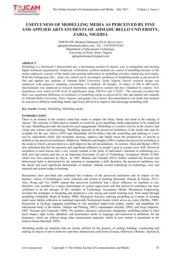
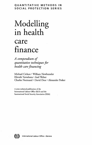
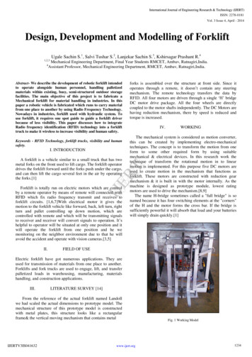
International Journal of Engineering Research & Technology (IJERT)ISSN: 2278-0181Vol. 3 Issue 4, April - 2014Design, Development and Modelling of ForkliftUgale Sachin S.1, Salvi Tushar S.2, Lanjekar Sachin S.3, Kshirsagar Prashant R.41,2,3Mechanical Engineering Department, Final Year Students RMCET, Ambav, Ratnagiri,India.Assistant Professor, Mechanical Engineering Department, RMCET, Ambav, Ratnagiri,India.4Abstract- We describe the development of robotic forklift intendedto operate alongside human personnel, handling palletizedmaterials within existing, busy, semi-structured outdoor storagefacilities. The main objective of this project is to fabricate aMechanical forklift for material handling in industries. In thispaper a robotic vehicle is fabricated which runs to carry materialfrom one place to another by using Radio Frequency Technology.Nowadays in industries, forklift used with hydraulic system. Touse forklift, it requires one spot guide to guide a forklift driverbecause of less visibility. This paper discusses how to integrateRadio frequency identification (RFID) technology into a forklifttruck to make it wireless to increase visibility and human safety.Keywords - RFID Technology, forklift trucks, visibility and humansafety.I. INTRODUCTIONIV.WORKINGThe mechanical system is considered as motion converter,this can be created by implementing electro-mechanicaltechniques. The concept is to transform the motion from oneform to some other required form by using suitablemechanical & electrical devices. In this research work thetechnique of transform the rotational motion in to linearmotion is implemented. For this purpose five DC motors areused to create motion in the mechanism that functions asforklift. These motors are constructed with reduction gearmechanism & it is built in with the motor internally. As themachine is designed as prototype module, lowest ratingmotors are used to drive the mechanism.[8,9]The name H-bridge sometimes called a "full bridge" is sonamed because it has four switching elements at the "corners"of the H and the motor forms the cross bar. If the bridge issufficiently powerful it will absorb that load and your batterieswill simply drain quickly.[1]IJERTA forklift is a vehicle similar to a small truck that has twometal forks on the front used to lift cargo. The forklift operatordrives the forklift forward until the forks push under the cargo,and can then lift the cargo several feet in the air by operatingthe forks.[1]forks is assembled over the structure at front side. Since itoperates through a remote, it doesn‟t contain any steeringmechanism. The remote technology transfers the data byRFID. All four motors are driven through a single „H‟ bridgeDC motor drive package. All the four wheels are directlycoupled to the motor shafts independently. The DC Motors arehaving reduction mechanism, there by speed is reduced andtorque is increased.Forklift is totally run on electric motors which are controlby a remote operator by means of remote will connected withRFID which fix radio frequency transmit and receives toforklift circuits. [1,6,7]With electrical motor it gives themotion to the forklift vehicle like forward, back, left turn, rightturn and pallet controlling up down motion, which arecontrolled with remote and which will be transmitting signalsto receiver and receiver will convert signals to operation. It‟shelpful to operator will be situated at only one position and itwill operate the forklift from one position and he wemonitoring on the neighbor environment due to that he willavoid the accident and operate with vision cameras.[3,5]II.FIELD OF USEElectric forklift have got numerous applications. They areused for transmission of materials from one place to another.Forklifts and fork trucks are used to engage, lift, and transferpalletized loads in warehousing, manufacturing, materialshandling, and construction applications.III.LITERATURE SURVEY [14]From the reference of the actual forklift named Landollwe had scaled the actual dimensions to prototype model. Themechanical structure of this prototype model is constructedwith metal plates, this structure looks like a rectangularframe& the vertical moving mechanism that contains metalIJERTV3IS041632www.ijert.orgFig. 1 Working Model1234
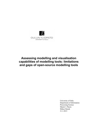
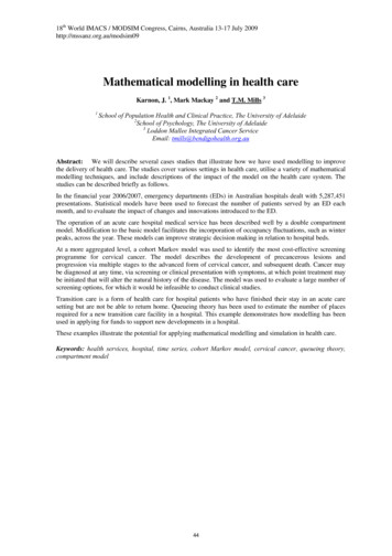
International Journal of Engineering Research & Technology (IJERT)ISSN: 2278-0181Vol. 3 Issue 4, April - 2014V.COMPONENTS[12]1.Design of driving chain and sprocket:A. Chain DriveChain drive helps to drive the system in both side (one ata time) using electric motor.Speed of motor 24 rpmTorque of motor 5kg-cm2𝜋𝑁𝑇Power (P) Driving chain: Two Sprockets with Diameter 25.07mm and49.77mm is used which have 12 and 24 teeth on it. Chain oflength 480mm and 80 links is convenient. 60 1.232 WKW Rating of the chain,𝐾𝑊 𝑡𝑜 𝑏𝑒 𝑡𝑟𝑎𝑛𝑠𝑚𝑖𝑡 Lifting chain: Two Sprockets with Diameter 25.07mm and49.77mm is used which have 12 and 24 teeth on it. Chain oflength 660mm and 110 links is convenient.B. ForkThe dimension of fork is 125x18x5 mm. The materialselected Mild steel. The max load carrying capacity is 50N.C. ShaftThe dimension of the shaft is 5mm diameter and220 mm length.The material selected is Mild steel. It is aninterconnection between primary and secondary chain drive 1.71 10 3 kW1 0.72𝑘𝑠 𝑆𝑒𝑟𝑣𝑖𝑐𝑒 𝑓𝑎𝑐𝑡𝑜𝑟 1𝑘1 𝑚𝑢𝑡𝑖𝑝𝑙𝑒 𝑠𝑡𝑟𝑎𝑛𝑑 𝑓𝑎𝑐𝑡𝑜𝑟 1𝑘2 𝑡𝑜𝑜𝑡 𝑐𝑜𝑟𝑟𝑒𝑐𝑡𝑖𝑜𝑛 𝑓𝑎𝑐𝑡𝑜𝑟 0.72Select chain no. 04-1Specification:Pitch – 6mmRoller dia – 4mmWidth – 2.8mmWeight – 0.12kgf/mDia. of driving sprocket,𝑝𝐷1 180sin ( 6𝑧1)180)13sin (E. TensionerIt is used to maintain the tension in secondary chaindrive. 25.07𝑚𝑚For driven sprocket,𝑧 𝑁13 𝑁 1 2 2F. BearingSKF 618/6 bearing is selected which is having I.D. 6mm and O.D. 13 mm. 𝑁2 12𝑟𝑝𝑚Dia. of driven sprocket,𝑝𝐷2 180G. Wheel motorIt function is to travel to and fro. There are 4 no ofmotor of 30rpm each.H. Guided Belt DriveIt is connected between two wheels at 350mm toprovide better traction in worst industrial floor condition. Thetrack width is 330mm.VI. DESIGN [12,13]The design of the mechanical assembly is derived from thescaled dimension the forklift named Landoll forklift truck ofthe Japanese company. The material selected to prepare theprototype model is Mild Steel due to its properties likemalleability as it can be hammered and pressed into any shape,ductility as it can be bent easily and versatile and in the last ismost common, cheap, strong and stiff. [2]For the electrical point of view, we had used anAT89C2051 microcontroller; the output of this controller isfed to the RF transmitter. This transmitter is designed togenerate a very high frequency of 433 MHz & it is used ascarrier frequency.[3,10]IJERTV3IS041632 𝑘𝑠𝑘 1 𝑘 21.232 10 3 1IJERTD. Geared MotorIt drives the primary chain drive at 24rpm. Thetorque is about 5 kg-cm and the power input is 12V DC.602𝜋 24 5 10𝑧 2 𝑁1sin ( 626 24𝑧2)180)26sin ( 49.77𝑚𝑚Centre distance between the sprockets should be between 30pto 50p,Assume a 30p 30 6 180𝑚𝑚Calculation of no. of links in chain,2𝑎𝑧1 𝑧2𝑧2 𝑧1 2 𝑝𝐿𝑛 () 𝑝22𝜋𝑎𝐿𝑛 80linksExact center distance,𝑝𝑧 1 𝑧 242a {[𝐿𝑛 [𝐿𝑛 𝑧 1 𝑧 22]2 8𝑧 2 𝑧 1 22𝜋} 181.07mmLength of chain,L 𝐿𝑛 𝑝 80 6 480𝑚𝑚Avg. velocity of chain,𝜋𝐷 𝑁V 1 1www.ijert.org 60𝜋 25.07 24601235
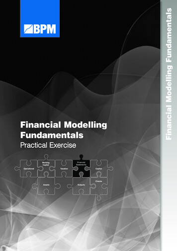
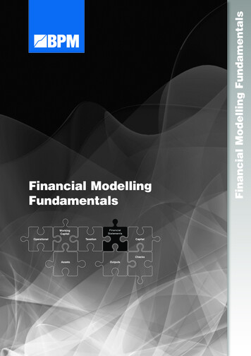
International Journal of Engineering Research & Technology (IJERT)ISSN: 2278-0181Vol. 3 Issue 4, April - 2014 31.50 𝑚𝑚 𝑠𝑒𝑐Tangential force due to power transmission,102 𝑃𝑃𝑡1 𝑉102 1.71 10 3 . 𝑃 𝑖𝑛 𝐾𝑊31.50 10 3 5.53 Kgf 55.37 NTension due to sagging of chain,𝑃𝑠1 𝑘 𝑤 𝑎 2 0.12 181.07 10 3 0.043𝐾𝑔𝑓 0.43𝑁K coefficient of slag (for 𝜃 40 ) 2w weight of chaina central distance2.𝑅2 𝑅4 78.32𝑅2 1.7 86.094 9.2 𝑅4 16.7 0 𝑅2 34.39𝑁𝑅4 43.92𝑁1.7cm7.5mm7.5cm24Pt1Pt3PS1 W31Fig. 2 Support Shaft layout47.95 NPS330.37 NDesign of lifting Chain and Sprocket:Dia. of driving sprocket,𝑝𝐷1 180sin ( 6𝑧134.39NFig. 3 Forces in vertical plane) 49.77𝑚𝑚180)26sin (43.92 N4040.64 N-mmDia. of driven sprocket,𝑝𝐷2 180sin ( 6𝑧2180)13sin () 25.07𝑚𝑚584N-mmCalculation of no. of links in chain,2𝑎𝑧1 𝑧2𝑧2 𝑧1 2 𝑝𝐿𝑛 () 𝑝22𝜋𝑎𝐿𝑛 110 linksExact center distance:𝑝𝑧 1 𝑧 242a {[𝐿𝑛 [𝐿𝑛 𝑧 1 𝑧 22]2 831.062 N-3.162NFig. 5 Forces in horizontal plane𝑧 2 𝑧 1 22𝜋a 271.21mmLength of chain,L 𝐿𝑛 𝑝 110 6 660𝑚𝑚Avg. velocity of chain,𝜋𝐷 𝑁𝜋 49.77 12V 1 1 31.27 𝑚𝑚 𝑠𝑒𝑐6060Tangential force due to power transmission,102 𝑃102 1.71 10 3𝑃𝑡3 . 𝑃 𝑖𝑛 𝐾𝑊𝑉31.27 10 3 5.57Kgf 55.7NTension due to sagging of chain,𝑃𝑠3 𝑘 𝑤 𝑎 1 0.12 271.27 10 3 0.032𝐾𝑔𝑓 0.324𝑁K coefficient of slag (for 𝑣𝑒𝑟𝑡𝑖𝑐𝑎𝑙) 1w weight of chaina central distance3.Design of shaft:[2,11,12,17]Material: - 30C8; 𝑆𝑦𝑡 400𝑁 𝑚𝑚2From fig. 3,For vertical plane,IJERTV3IS04163227.89 N Fig. 4 Bending Moment DiagramIJERTCentre distance between the sprocket should be between 30pto 50p,Assume a 45p 45 6 270𝑚𝑚528 NmmFig. 6 Bending Moment Diagram4040.64Nmm787.74NmmFig. 7 Resultant Bending Moment Diagram688.67 N-mm688.67 N-mmFig. 8 Torsional Moment DiagramForm fig. 4,Bending Moment,𝑀1 0𝑀2 34.39 1.7 58.4𝑁 𝑐𝑚 584𝑁 𝑚𝑚𝑀3 43.92 7.5 1.7 404.064𝑁 𝑐𝑚 4040.6𝑁 𝑚𝑚𝑀4 0www.ijert.org1236
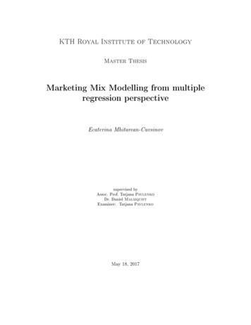
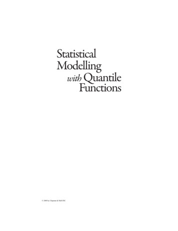
International Journal of Engineering Research & Technology (IJERT)ISSN: 2278-0181Vol. 3 Issue 4, April - 2014From fig. 5,For horizontal plane,𝑅2 𝑅4 27.9𝑅2 1.7 𝑅4 16.7 0 𝑅2 31.06𝑁𝑅4 3.162𝑁From fig. 6,Bending Moment, ( ve)𝑀1 0𝑀2 31.062 1.7 10 528𝑁 𝑚𝑚𝑀4 0From fig. 7,Resultant Bending moment,𝑀2 584.6 2 528 2𝑀2 787.74N mm𝑀3 4040.6 2 0 4040.64 N mmNow,16𝜏𝑚𝑎𝑥 𝑀𝑏 2 𝑀𝑡 2𝜋𝑑 3And𝑆0.5 � 𝑠𝑦 133.33𝑁/𝑚𝑚2𝐹𝑂𝑆1.5From fig. 8,𝑀𝑡 (𝑃𝑡1 -𝑃𝑠1 ) 𝑅 55.37 0.43 12.53 688.67N mmFrom, 𝜏𝑚𝑎𝑥 3 𝑀𝑏 2 𝑀𝑡𝜋𝑑 𝑑 5.38 6𝑚𝑚4.Deflection,𝑦𝑚𝑎𝑥 8𝐸𝐼3 9.81 12.5 8 2.1 105 0.0188 𝑚𝑚416 33125. Design of Bearing: [15,16]Axial load, Fa 0NRadial load, Fr 30NP (X Fr Y Fa )P 30NN 24rpmAssuming life of bearing is 5000 hrs.L10h 800 hrs.Life in million revolutions𝐿𝑥 60 𝑥 L10mr 10h 6103000 𝑥 60 𝑥 24 10 6 4.32 million revolutionDynamic load carrying capacity,C P x (L10mr)1/k2Design of Fork: [4]𝑊𝐿4Where, k 3 for ball bearingC 30 x (4.32)1/3 48.85 N Selected bearing is SKF 618/6IJERT16 -0.0022NmCase 1:- By considering fork as a cantilever beam with pointloading.WFig. 9Deflection on fork by point loadW 3kgBy point load,𝑀𝑥 𝑊 𝐿 -3 9.81 12.5 10 3 -0.367NmDeflection,𝑊𝐿33 9.81 12.5 3𝑦𝑚𝑎𝑥 3𝐸𝐼16 333 2.1 10512 2.5344 10 3 𝑚𝑚Fig. 11Prototype ModelVII.Case 2:- By considering fork as a cantilever beam withUDLuniform distributed loadFig. 10 Deflection on fork by UDLNow 𝑀𝑥 𝑊 𝐿22 3 9.81 12.5 10 3IJERTV3IS041632CONCLUSIONThe main advantage of using this technology is to increasethe safety of operator by operating the forklift from certaindistance. This increases the efficiency of the productivity,because human errors due to the poor visibility can beminimized. During the trail run we have tested the range &we found that the transmitter is able control the forklift from adistance of 15feet.32www.ijert.org1237
International Journal of Engineering Research & Technology (IJERT)ISSN: 2278-0181Vol. 3 Issue 4, April - 2014VIII.FUTURE SCOPEAs per the present situation considering the casualty rateswe had come up with an enhanced system of fork liftingmechanism which emphasizes over the safety features alongwith more precise working. Web-cam conciliated with sensorswill reduce exertion on operator and reduce the casualties.Way Tipper Mechanism”. International Journal of Research in AdventTechnology, Vol.2, No.4, pp. 261-265, Vol.2, No.4, April 2014. April2014E-ISSN: 2321-9637.ACKNOWLEDGMENTWe would like to thank Prof. Kshirsagar Prashant R. forhis guidance. His enthusiasm and patience, as well as histechnical expertise, were essential in helping us overcomemany obstacles. Without him this dissertation would not havebeen ][12][13][14][15][16][17]Aashishkumar L Sharnangat. "Design of Wireless Operated (On RFID)Forklift in Warehouse." “The International Journal of Engineering andScience”(IJES)published on 20th April 2013.R.P.Kumar Rompicharla – PG Student, Dr. K. Rambabu – AssociateProfessor,“Design And Analysis Of Drive Shaft With CompositeMaterials” Affiliated to Andhra University, Research ExpoInternational Multidisciplinary Research Journal Volume - II, Issue - IIJune - 2012 ISSN: 2250 -1630.Andreas JUNGK, Gerd HEISERICH and Ludger OVERMEYER,“Antenna Concepts for RFID on Forklift Trucks” fromLeibnizUniversity at Hannover, Institute of Transport and AutomationTechnology An der University at 2, 30823 Garbsen, Germany.ISO. ISO Standard 2328:2007, Fork-lift trucks – Hookon type forkarms and fork arm carriages – Mounting dimensions. ISO, secondedition, 2007.P. Nikitin and K. Rao, “Performance of RFID Tags with Multiple RFPorts,” Antennas and Propagation Society International Symposium2007, pp. 5459 – 5462, June 2007.P. Nikitin and K. Rao, “Performance limitations of passive UHF RFIDsystems,” IEEE Antennas and Propagation Society InternationalSymposium 2006, pp. 1011–1014, July 2006.Y. Tikhov, “Comments on antenna design for UHF RFID tags: aReview and a Practical Application,” IEEE Transactions on Antennasand Propagation, vol. 54, 2006.“Forklift Stability and Other Technical Safety Issues” AccidentResearch Centre Monash University Victoria 3800 Australia (Authors:J Lambert & Associates) an initiative funded by WorkSafe, Victoria.April 2003M. Seelinger and J. D. Yoder, “Automatic visual guidance of a forkliftengaging a pallet,” Robotics and Autonomous Systems, vol. 54, no. 12,pp. 1026–1038, December 2006.G. Devita and G. Iannaccone, “Design criteria for the RF section ofUHF and microwave passive RFID transponders,” IEEE Transactionson Microwave Theory and Techniques, vol. 53, pp. 2978–2990,September 2005.Rangaswamy, T.; Vijayrangan, S. (2005). “Optimal sizing and stackingsequence of composite drive shafts”. Materials science, Vol. 11 No 2.India.Design of Machine Element-V. B. Bhandari ISBN-13: 978-0-07068179-8 (2011) pp.330-331; 544-562.Design Data – Data Book of Engineers (2007), published byKalaikhathir Achchagam, PSG College of Technology, Coimbatore,India pp. 4.1-4.38; 7.71-7.78.Study of actual forklift named Landoll Forklift Truck of KF Deep Groove Ball Bearing KF Open Deep Groove Ball Bearing 6x13x3.5mm/product info.htmlAmboji Sudhakar R.1, Humane Yogesh A.2,Chavan Rohan R.3,PatilJyotsna C.4,Kshirsagar Prashant R.5 “Design and Fabrication of ThreeIJERTV3IS041632IJERT[1]www.ijert.org1238
A forklift is a vehicle similar to a small truck that has two metal forks on the front used to lift cargo. The forklift operator drives the forklift forward until the forks push under the cargo, and can then lift the cargo several feet in the air by operating the forks.[1] Forklift is totally run on electric motors which are control