Transcription
OPERATION MANUAL429EX429 ARINC TX/RXMANUAL NUMBER: 06-1001-06 (Hard Copy)E6-1001-06 (CD-ROM)REVISION: 0DATE: 04/26/2006WARNING: INFORMATION SUBJECT TO EXPORT CONTROL LAWSThis manual may contain information subject to the International Traffic in Arms Regulation (ITAR) or the ExportAdministration Regulation (EAR) which may not be exported, released, or disclosed to foreign nationals inside oroutside of the United States without first obtaining an export license. A violation of the ITAR or EAR may besubject to a penalty of imprisonment and/or fines under 22 U.S.C.2778 of the Arms Export Control Act or section2410 of the Export Administration Act. Include this notice with any reproduced portion of this document.This document is proprietary to Aeroflex JcAIR Test Systems,and is not to be reproduced or otherwise disseminated without the written consent ofAeroflex JcAIR Test Systems.400 New Century Parkway – New Century, Kansas – 66031Telephone: (800) 237-2831 / (913) 764-2452 Fax: (913) 782-5104www.aeroflex.com
Aeroflex JcAIR Test Systems Operation ManualREVISION HISTORY BY DRAWING NUMBERMANUAL: 429EX ARINC TX/RX OperationREVISION: 0 – April 26, 2006DRAWING NO.REV.LEVELSection ISection IISection IIISection IVSection V00000Appendix A0DRAWING NO.REV.LEVELDRAWING REVISION HISTORY – 429EX OPERATION – APRIL 26, 2006 – PAGE 1 OF 1
ELECTROSTATIC DISCHARGE GENERAL WARNINGS FOR ALL EQUIPMENTCAUTION:THIS EQUIPMENT MAY CONTAIN ELECTROSTATIC DISCHARGE (ESD) SENSITIVECOMPONENTS. TO PREVENT ESD SENSITIVE EQUIPMENT FROM POSSIBLEDAMAGE, OBSERVE THE FOLLOWING PRECAUTIONS WHEN HANDLING ANY ESDSENSITIVE COMPONENTS, OR UNITS CONTAINING ESD SENSITIVECOMPONENTS:a.Maintenance or service personnel must be grounded though a conductive wrist strap, or a similargrounding device, using a 1 MΩ series resistor for equipment protection against static discharge,and personal protection against electrical shock.b.All tools must be grounded (including soldering tools) that may come into contact with theequipment. Hand contact will provide sufficient grounding for tools that are not otherwisegrounded, provided the operator is grounded through an acceptable grounding device such as awrist strap.c.Maintenance or service of the unit must be done at a grounded, ESD workstation.d.Before maintenance or service of the equipment, disconnect all power sources, signal sources,and loads connected to the unit.e.If maintenance or service must be performed with power applied, take precautions againstaccidental disconnection of equipment components. Specifically, do not remove integratedcircuits or printed circuit boards from equipment while the equipment has power applied.f.All ESD sensitive components are shipped in protective tubes or electrically conductive foam.The components should be stored using the original container/package when not being used ortested. If the original storage material is not available, use similar or equivalent protectivestorage material.g.When ESD sensitive components are removed from a unit, the components must be placed on aconductive surface, or in an electrically conductive container.h.When in storage or not being repaired, all printed circuits boards must be kept in electricallyconductive bags, or other electrically conductive containers.i.Do not unnecessarily pick up, hold, or directly carry ESD sensitive devices.Failure to comply with these precautions may cause permanent damage to ESD sensitive devices. Thisdamage can cause devices to fail immediately, or at a later time without apparent cause.05-0035-00 Rev 03
WARNING AND CAUTION SYMBOLS USED IN THIS MANUALDirect CurrentThis symbol indicates that theequipment requires direct currentinput.Caution (refer toaccompanyingdocuments)Attention – refer to the manual. Thissymbol indicates that informationabout usage of a feature is containedin the manual.CAUTIONThe CAUTION notice denotes ahazard. It calls attention to anoperating procedure, practice, or thelike, which, if not correctly performedor adhered to, could result in damageto the product or loss of importantdata. Do not proceed beyond aCAUTION notice until the indicatedconditions are fully understood andmet.
GENERAL WARNINGS AND CAUTIONS APPLICABLE TO THIS EQUIPMENTBATTERY CHARGING WARNINGThis equipment has a recharging circuit for rechargeable cells. Use only NiCad size “AA” cells.WARNINGDo not use the equipment in a manner not specified in this manual!CLEANING WARNINGKeep the equipment dry to avoid electrical shock to personnel or damage to the equipment. To preventdamage, never apply solvents to the equipment housing. For cleaning, wipe the equipment with a cloththat is lightly dampened with water, mild detergent, or alcohol. Do not use aromatic hydrocarbons,chlorinated solvents, or methanol-based fluids.
Aeroflex JcAIR Test Systems Operation ManualTABLE OF CONTENTSSECTION IGENERAL G AND CAUTION SYMBOLS . ----DECLARATION OF CONFORMITY . ----INTRODUCTION . 1-1EQUIPMENT DESCRIPTION . 1-1TECHNICAL CHARACTERISTICS . 1-2UNITS & ACCESSORIES SUPPLIED . 1-3SECTION RAL INFORMATION. 2-1UNPACKING AND INSPECTING EQUIPMENT . 2-1EQUIPMENT INSTALLATION . 2-1Battery Charging . 2-1Connection To User Equipment. 2-1Jumper Plug Fabrication . 2-1POST INSTALLATION CHECK . 2-2Unit Self Test. 2-2SECTION 3.2.23.3.2.33.3.2.43.3.2.53.3.2.63.3.3GENERAL OPERATION INSTRUCTIONS . 3-1Hex Display Mode . 3-1Engineering Display Mode . 3-1Receive & Transmit Modes. 3-1TX Mode. 3-2RX Mode . 3-2Miscellaneous . 3-3Speed & Parity Select/Display . 3-3Power Saver Mode . 3-3CONTROL FUNCTIONS . 3-3Controls & Indicators. 3-3OPERATING EXAMPLE. 3-7Transmitter Functions . 3-7Entering TX Labels & Protecting Data . 3-7Receiver Functions . 3-9Normal RX Mode . 3-9Filter Mode . 3-9Normal Trap Mode . 3-10Label/Data Only Trap Mode. 3-10Data Trap Mode . 3-10Trigger Trap Mode . 3-11Changing Equipment ID Codes . 3-12429EX - Rev. 0 – April 26, 2006 - Page TC-1
Aeroflex JcAIR Test Systems Operation ManualSECTION IVTHEORY OF OPERATIONParagraph4.14.1.14.1.24.1.3PageGENERAL CIRCUIT THEORY . 4-1Display Board. 4-1Digital Board. 4-1Analog Board . 4-2SECTION VMAINTENANCE5.1INTRODUCTION . 5-1APPENDIX AA.1429EX DEFINED LABELS & DEFAULT DATA . A-1429EX - Rev. 0 – April 26, 2006 - Page TC-2
Aeroflex JcAIR Test Systems Operation ManualSECTION I - GENERAL INFORMATION1.1 INTRODUCTIONThis manual provides operational information for the Aeroflex JcAIR Test Systems Model 429EX ARINC429 Transmitter/Receiver.1.2 EQUIPMENT DESCRIPTIONThe 429EX provides avionics technicians and line maintenance personnel with a convenient, easy to usetool for testing and troubleshooting ARINC 429 avionics systems.Transmitter features:- Data entry in Hexadecimal or Engineering Units- Can transmit up to 10 labels simultaneously- Selectable (Lo or Hi speed) bit rate- Selectable (Odd or Even) word parity- Selectable (4 to 59995 ms) word rate- Selectable Hex I.D. for display of data per ARINC 429-11 (Attach. 2)- Non-volatile memory storage- Data slewing of non-RF labels- On/Off toggling of individual data bits 11 through 29- LED display of transmitted word parityReceiver features:- Data display in Hexadecimal or Engineering Units- Trapping and storing of up to 255 words (511 in Data Only mode)- Allows trapping of block data protocols or alphanumeric data strings- Non-volatile memory of trapped data- Automatic scrolling of trapped data- Individual display of bits 11 through 29- Selectable Hex I.D. for display of data per ARINC 429-11 (Attach. 2)- Selectable (Lo or Hi speed) bit rate- LED display of received word parityOther features:- Liquid crystal display- Portability- Self-contained, rechargeable NiCad batteries- Available with either 110 V ac or 220 V ac battery charger- Rugged, compact case- Optional carrying case429EX - Rev. 0 – April 26, 2006 - Page 1-1
Aeroflex JcAIR Test Systems Operation Manual1.3 TECHNICAL 36 kg) 3 lbs.DIMENSIONS:Height:Width:Depth:(18.42 cm) 7.25 in.(11.43 cm) 4.5 in.(6.35 cm) 2.5 in.POWER REQUIREMENTS:INPUT:ENVIRONMENTAL CONDITIONSOPERATING TEMPERATURE:ENVIRONMENT:ALTITUDE:RELATIVE HUMIDITY:Pollution DegreeOvervoltage Category110 V ac/60 Hz/500 mAOR230 V ac/50 Hz/300 mAORSix (6) internally mounted AA sizerechargeable NiCad batteries.5 C to 40 CFor indoor use onlyNot for use over 2000 ms30% to 80% relative humidity1IIARINC 429 TRANSMITTERPulse Rise/Fall Times:Low SpeedHigh Speed10.0 5.0 µs1.5 0.5 µsVoltage Levels (Line A to B):HINULLLO 10.0 1.0 V dc0.0 0.5 V dc-10.0 1.0 V dcOutput Impedance:75 5 Ω (Line A to B)Bit Rate:Low SpeedHigh SpeedWord Rate:4 to 59 998 msParity:ODD or EVEN12.5 kbps 0.5%100.0 kbps 0.5%ARINC 429 RECEIVERVoltage Levels (Line A to B):HINULLLO 6.5 to 13.0 V dc 2.5 to - 2.5 V dc-6.5 to -13.0 V dcBit Rate:Low SpeedHigh Speed8 to 20 kbps80 to 125 kbpsWord Rate: 2 ms averageInput Impedance:12 k Ω minimum (balanced)429EX - Rev. 0 – April 26, 2006 - Page 1-2
Aeroflex JcAIR Test Systems Operation Manual1.4 UNITS AND ACCESSORIES SUPPLIEDThe Aeroflex JcAIR Test Systems Model 429EX, JPN: 01-1001-05, is supplied with either a 110 V acbattery charger or a 230 V ac battery charger. Two 3-conductor 1/4" phone plugs are included forfabrication of cables to connect to the transmit and receive jacks of the unit. (See Section 2.3.3 forfabrication instructions.) The accessories provided are as follows:JcAIR TIONBattery Charger 110 V ac to 9 V dc 500 mABattery Charger 230 V ac to 9 V dc 500 mA3-Conductor 1/4" Phone Plugs429EX Maintenance Manual429EX - Rev. 0 – April 26, 2006 - Page 1-3
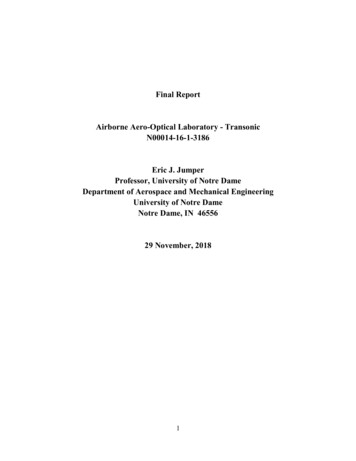
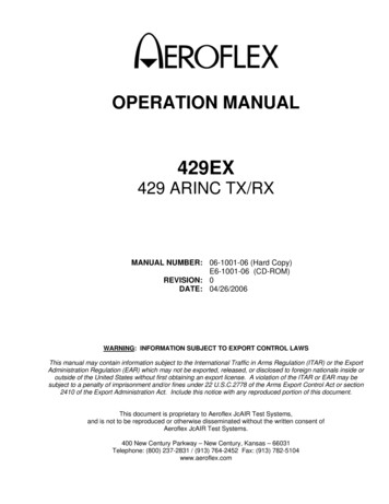
Aeroflex JcAIR Test Systems Operation ManualSECTION II - INSTALLATION2.1 GENERAL INFORMATIONThis section contains information relating to the unpacking and inspection of the unit. Also included isinformation concerning charging of the internal batteries and an explanation of the unit's self test routine.2.2 UNPACKING AND INSPECTING EQUIPMENTCarefully remove the Aeroflex JcAIR Test Systems 429EX and battery charger from the packing box.Visually inspect the units for any damage incurred during shipment. Should there be damage, save thepacking box to show the shipping company when submitting your claim. It is generally a good idea tosave the packing box should it become necessary to store or ship the unit.2.3 EQUIPMENT INSTALLATION2.3.1 BATTERY CHARGINGThe batteries were fully charged when the unit was shipped from the factory. However, if the unit hasbeen stored for an extended period of time, the batteries may have become discharged. Plug the chargerinto an appropriate voltage outlet (U.S. as well as international voltage chargers are available). A 4 to 5hour charge should refresh the batteries. The 429EX may be operated while charging or with the chargerdisconnected. With fully charged batteries, the unit will operate for approximately 3 to 6 hours.CAUTIONTo avoid possible damage to the battery charger, it is recommended that you do NOT have the chargerconnected to the wall outlet when connecting or disconnecting the charging plug to the 429EX.2.3.2 CONNECTION TO USER EQUIPMENTConnect the Aeroflex JcAIR Test Systems 429EX TX output jack to the input of the UUT and the 429EXRX input jack to the output of the UUT using 3-conductor 1/4 inch phone plugs (see paragraph 1.4).2.3.3 JUMPER PLUG FABRICATIONJumper plugs should be fabricated using 2-conductor braided shield cable. The shield should befolded back onto the insulation and the clamp on the connector should be crimped around theshielding. Also, once the shield is clamped, solder should be added to ensure a stableconnection is made between the clamp and wire shield. Refer to figures 2-1 and 2-2.Figure 2-1. Phone Jack Jumper Plug429EX - Rev. 0 – April 26, 2006 - Page 2-1
Aeroflex JcAIR Test Systems Operation ManualFigure 2-2. Phone Plug Termination2.4 POST INSTALLATION CHECK2.4.1 UNIT SELF TESTThe 429EX performs a self test routine on initial power up. The following tests are performed:1. The message EX VERSION *.* is displayed. (*.* firmware revision). Red LED's on the frontof the unit will be lit for approximately 0.5 seconds each in the following order; EVEN and ODDParity, TX and RX. For the remainder of the test, unless an error condition exists, the LED's areextinguished. If one of the LED's fails to light, the unit should still function properly, but the LEDshould be replaced at the earliest opportunity. If all LED's fail to illuminate and the display isblank or displays random data, then a catastrophic unit failure has occurred or the batteries arecompletely discharged.2. The EPROM is checked by summing all memory locations and comparing the result to theknown checksum. If the checksums don't match, the unit will signal a checksum error by flashingthe RX LED and will attempt to write CHECKSUM ERROR to the display. If the entire EPROMhas failed, however, or if one of the locations in the checksum sub-routine is bad, the programwill not be able to execute properly.3. The 429EX has RAM in two independent IC's. The unit tests each RAM section separately fordata retention and address integrity. It begins by writing the lower 8 bits of the location addressto the location. After writing to all locations of the section. It then reads each location and checkits value. If all is correct, it will repeat this sequence with the exception that it will write thecomplement of the lower 8 bits of the location address to the location. It performs this sequencefor each RAM section.If the first IC fails this test, the unit will flash the EVEN parity LED and attempt to write NSC RAMERR to the display. This indicates that U5 has failed its test. If the second IC fails this test, theunit will flash the ODD parity LED and will attempt to write 6116 RAM ERR to the display. Thisindicates that U3 has failed its test. The PROGRAM will then loop indefinitely reading from thefailed location.4. The 429EX has a loop back feature on the digital board to completely test the digital portion ofthe transmit and receive circuitry. The unit will turn on the loopback circuitry and transmit a wordwith a label of 0 and a data pattern of AA55AA (hex). After a brief pause, the unit will read itsreceive buffer and check the data against the transmitted data. If the data is not what isexpected, the unit will flash the TX LED and attempt to write LOOP BACK FAILED to the display.No further operations will be possible until the cause of the failure is corrected.The Loop test and Ram tests are not performed if the unit Trap mode is active.If all tests have been successfully completed, the unit will display SELF TEST OK forapproximately 2 seconds and will then enter the operational transmit mode and display thenumber of different labels currently being transmitted.429EX - Rev. 0 – April 26, 2006 - Page 2-2
Aeroflex JcAIR Test Systems Operation ManualSECTION III - OPERATION3.1 GENERAL OPERATION DESCRIPTIONThe Aeroflex JcAIR Test Systems 429EX is a single channel ARINC 429 transmitter and receiver.It can receive and display all ARINC 429 labels (001 - 377). It can simultaneously output up toten 429 words. Data can be displayed and entered in hexadecimal or engineering formats.3.1.1 HEX DISPLAY MODEThe HEX mode has two types of data entry and display. The first type allows display and entry of bits 329 in hexadecimal format. The characters represent bits 32 through 9 (starting with bit 32) of the 32 bitword in six 4-bit nibbles. Each 4-bit nibble is derived from the BCD equivalent of the binary value. Forexample:Data field in binary 1001Equivalent hex value 9001021111F000111010A01015The label will be displayed in octal. The SDI (bits 10-9) is then displayed in binary. Bits 32-9 of the wordare then displayed in HEX. On the far right of the display will be the SSM bits (31-30) of the word. Thesecond type in HEX mode allows display and entry of bits 31-9 in binary format. The SDI bits (10-9) andSSM bits (31-30) each have their own screen. The remaining bits (29-11) each have their own individualscreen. Word rate for the word is also available on a dedicated screen in the HEX mode.3.1.2 ENGINEERING DISPLAY MODEThe ENG (Engineering) mode allows data entry and display in engineering unit formats (Feet, Knots,MHz, etc.). The label definition will determine the number of screens required for display of the possiblefields of the word. Label definition may be changed by entering a new EQID (Equipment Identifier). Thisis accomplished by pressing the EQID key which will display the current EQID number. To change it,press the EDIT key, enter the desired two digit number and press the ENTER key. If the new EQID isvalid (per ARINC 429-11, Attach. 2) for the currently selected label, then the label will be decoded anddisplayed according to that definition. If the EQID is invalid for the label, or no EQID number is entered,the default definition (EQID 00) will be used (see Appendix A of this manual for the default labeldefinitions). The last EQID entered will remain active until changed or until the unit is turned off (unless inTrap or Protect mode). Some labels have definitions that don't have an assigned EQID and are not thedefault definition. These have been arbitrarily assigned EQID of FF.NOTEBITE Status Word has been assigned the same EQID as the BITE Command Word (7E) and will bedisplayed in engineering format. However, due to the many variations of data types for the word, it mustbe entered in HEX format.3.1.3 RECEIVE AND TRANSMIT MODESThere are two distinct modes of system operation; RX (Receiver) mode and TX (Transmit) mode.Selection of these modes and all other display operations are accomplished by keypad or slide switchentry.429 EX - Rev. 0 – April 26, 2006 - Page 3-1
Aeroflex JcAIR Test Systems Operation Manual3.1.3.1 TX ModeThe transmitter is capable of outputting up to ten 32 bit words in ARINC 429 or 419 bipolar RZ (Return-toZero) format. The word rate for each of the ten can be set independently. The word rate can be as fastas 4 ms or as slow as 59998 ms. If the word rate is not specified, the unit will set it to the default valueas defined as the minimum word rate in the ARINC 429-11 specification. The transmitter automaticallyinsures at least a 4 bit time (Low Speed) separation between adjacent words.The transmitter section may be placed into a PROTECTED mode of operation if desired. This isaccomplished by pressing the TRAP key while the unit is in the transmit mode of operation (TX LED lit).Subsequent presses of the TRAP key will cause the display to toggle between PROTECTED and NOTPROTECTED. If turned on, this feature protects the user entered parameters from changing when theunit is powered off. When power is restored to the unit, it will resume operation where it was at powerdown. If the PROTECTED mode is turned off, the unit will clear the transmitter section on power up. Theunit will stay in the selected mode (PROTECTED or NOT PROTECTED) until changed by the user, evenif the unit power is cycled.The data for most labels with engineering definitions can be SLEWED. This means that the data willdynamically change value according to user defined parameters. There will be 4 slew screens in the datamode for any label with slew capability. The first screen is a SLEW screen that defines the amount ofchange in data. When this parameter is set to "0" (default), no slewing will occur. The second screen isthe MAX screen which defines the upper limit that the data is allowed to slew to. The third screen is theMIN screen which defines the lower limit that the data is allowed to slew to. Either parameter may bepositive or negative (dependent on ARINC definition for the label), but the MAX parameter MUST belarger than the MIN parameter. Note that only bits 28 to 17 of the limits will be used in the limit check. Allother bits are ignored and will be truncated upon user entry of new limit values. The fourth screen turnsthe ALT (Alternate) mode on and off. If this mode is on, the data will slew to the limit in the direction it isgoing. When the limit is reached, the data will reverse direction and then slew to the opposite limit.When this limit is reached, the data will again reverse itself. If ALT is off, the data will slew in the directionentered in the SLEW parameter (positive or negative) to the limit and then reset to the value defined forthe opposite limit (data wraps around).3.1.3.2 RX ModeThe receiver has the capability of receiving and storing up to 255 (511 in DATA ONLY mode) high or lowspeed 32 bit words in ARINC 429 or 419 RZ format. There are three mutually exclusive receiver modes ofoperation. Each mode has a screen that shows the count of words received, the label and description, orthe data field currently selected.NORMAL mode (default) is a dynamic mode that displays all unique labels received. In this mode thescreen is updated 4 times per second with the latest data received.FILTER mode is identical to NORMAL mode with the exception that words received may be filtered.Words may be filtered in 1 of 4 combinations; All Labels/All SDI, Specific Label/All SDI, All Labels/SpecificSDI, and Specific Label/Specific SDI. Any words that do not meet the filter parameters will be discarded.TRAP mode is the third and most powerful mode. This is a static mode of operation which captures andstores the data for detailed analysis. Words are received and stored in the trap buffer in their order ofoccurrence. They will remain in the buffer until the trap mode is turned off, even if the unit power isturned off. In normal TRAP mode, up to 255 unique words may be stored. In this mode, the time that haselapsed since the previous word is stored as the rate. In DATA ONLY TRAP mode, up to 511 words(must be the same label) are stored. The rate is invalid in this mode of operation.429 EX - Rev. 0 – April 26, 2006 - Page 3-2
Aeroflex JcAIR Test Systems Operation ManualThe TRAP has user definable trigger and filter parameters. A trigger may be set up so that trapping willnot occur until the trigger specs are met. Triggering specs may be set in 1 of 4 combinations: Don't CareLabel/Don't Care Data (No Trigger), Specific Label/Don't Care Data, Don't Care Label/Specific DataPattern, Specific Label/Specific Data Pattern. Filtering specs may be set to filter the data in 1 of 4combinations: All Labels/All Data, Specific Label/All Data, All Labels/Specific Data Pattern, and SpecificLabel/Specific Data pattern. The data pattern for each spec can be from 1 to 24 bits. If a data pattern isentered for either spec, the user will be prompted for a CARES mask. If a bit is set in this mask, thecorresponding bit in the received data will be checked against the same bit in the desired data pattern.The user may simply press the enter key if the prompted parameter is a don't care to the user. Data andcare patterns must be entered in hexadecimal (up to 6) characters, if used. As an example, if a DATApattern of 000001 and a CARES pattern of 000003 (default) is used then only the SDI bits (10 - 9) will bechecked for an SDI of 01. The status of a bit in the DATA pattern is irrelevant if the corresponding bit inthe CARES pattern is not set.3.1.4 MISCELLANEOUS3.1.4.1 Speed and Parity Select/DisplayThe transmitter and receiver can operate at either 12.5 kbps (Lo Speed) or 100 kbps (Hi Speed). Eachmode's speed can be set independently of the other. The parity of the words being transmitted can be setfor either ODD or EVEN parity. The 429EX will automatically correct the entered data to be transmitted ifthe data entered by the user is in conflict with the selected TX parity. An LED indicator will show the parityselected for transmitted words if in the TX mode or the parity of the currently displayed word if in the RXmode.3.1.4.2 Power Saver ModeTo minimize battery drain, the 429EX has the capability to sense there has been no activity (keypad, TX,or RX) for at least 5 minutes. When this happens, the 429EX will shut down some of it's circuitry and goto "sleep". In this state, the 429EX is fully functional, but it is in a low current drain wait state. The LCDscreen will be blank, but either the TX or RX LED will be lit. Any keypad or RX activity will reawaken the429EX to its normal operation mode.3.2 CONTROL FUNCTIONS3.2.1 429EX CONTROLS AND INDICATORS (Figure 3-1)(1) TRAP Mode KeyIN RX MODE. ON/OFF control for the TRAP mode. Pressing the ENTkey for any of the prompted parameters will cause a DON'T CARE to beused for that parameter. Data is automatically protected if unit ispowered off when TRAP is on.IN TX MODE. ON/OFF key for the PROTECT mode. If PROTECT is on,the transmit parameters will be protected when the 429EX is poweredoff.(2) AUTO Mode KeyIN RX MODE. ON/OFF key for AUTO scrolling mode. Allows theoperator to scroll through labels that have been received by TRAP mode.AUTO mode steps automatically through the word buffer and displaysthe number of trapped words as well as the engineering name of thelabel, if it is in the LABEL mode. If in the DATA mode, the AUTO modesteps to the same data menu for the next trapped word. Scroll keys allowscanning direction to be selected.IN EDIT MODE. While in the EDIT mode, this key allows thehexadecimal value C to be entered.429 EX - Rev. 0 – April 26, 2006 - Page 3-3
Aeroflex JcAIR Test Systems Operation Manual(3) TX Parity SwitchAllows operator to select ODD or EVEN transmit word parity.(4) TX SPEED SwitchAllows operator to select HI (100 kbps) or LO (12.5 kbps) speed transmitword rate.(5) TX Output PortAllows access to transmitter port using standard 3-conductor, 1/4" phoneplug.(6) RX Input PortProvides input to receiver port using standard 3-conductor, 1/4" phoneplug.(7) ARROW (Scroll) KeysAllows operator to scroll through display menus (10 transmitter slots, upto 511 receiver slots, or data menus). Allows selection of the scanningdirection in AUTO mode. If editing data of an ISO Alpha label (356 or357), the SCROLL keys will allow selection of the Alpha character tobe entered (SCROLL to the desired character and press ENT to select acharacter).(8) TX/RX IndicatorLED indicates that the system is in either transmitter (TX) or receiver(RX) mode of operation for display and entry of data.(9) PARITY IndicatorIN RX MODE. LED Indicates parity (ODD or EVEN) of word presentlydisplayed.IN TX MODE. LED Indicates selected transmit parity.(10) HEX/ENG SwitchAllows operator to select hexadecimal or engineering unit display andentry of data.(11) TX/RX KeyAllows operator to select whether the system is in transmit or receivemode of operation for display and entry of data. After selection of theTX/RX key, initial display indicates the number of labels beingtransmitted, received, trapped, or filtered. SCROLL keys should then beused for manual stepping through transmitter or receiver slots. TX/RXLED indicators above display will indicate current mode of operation.(12) RX SPEED SwitchAllows operator to select HI (100 kbps) or LO (12.5 kbps) receiverspeed.(13) DATA ENTRY KeysAllows operator to enter various data in hexadecimal or engineeringformats. Keys 0 to 9 and the "." and "-" keys are valid while in ENGmode. Keys 0 to F
OPERATION MANUAL 429EX 429 ARINC TX/RX MANUAL NUMBER: 06-1001-06 (Hard Copy) E6-1001-06 (CD-ROM) REVISION: 0 DATE: 04/26/2006 WARNING: INFORMATION SUBJECT TO EXPORT CONTROL LAWS This manual may contain information subject to the International Traffic in Arms Regulation (ITAR) or the Export